14. Automatic regulators. Classification of regulators according to the type of energy used, the laws of regulation, the nature of the regulatory impact. Scope, advantages and disadvantages.
Automatic regulators.
The device, with the help of which the control systems provide automatic maintenance of the technological value around the set value, is called an automatic regulator. The regulator is one of the elements of a closed system.
Max, which provides control with the lowest possible rms control error
The effect of the effect is to weaken the angiotensin receptor and stimulate the renin receptor. Similarly, there has been a reduction in proteinuria in diabetic nephropathy, which was also an adjunct to existing sartan therapy. Predictive studies are still being carried out.
Because renin is released by other stimuli such as osmo, chemo or presoreceptors, inhibition of the system is not sufficient. The main regulatory regimen of renin-angiotensin-aldosterone has grown into several parallel and equally important branches. However, treatments targeting activators of the kinin system, in particular bradykinin, for angiotensin degradation products, especially angiotensin 1-7, are also contemplated.
The input of the automatic controller is supplied with the current y t and given and 3 controlled value. Mismatch between them y t-i 3 leads to a change in the output value of the controller x p
This dependence in relative terms (at u = 0)
called regulation law. Each specific regulator has its own regulation law.
Clinical assessment of pulmonary hypertension, ischemic syndrome, or hypertension was most advanced in fasudil; it appears to be the most potent vasodilator ever tested. As you can see, interesting years lie ahead. Just hope the coming years of failed cardiac studies are over.
Methods for setting up two-coupled control systems
Preparation, purification and amino acid sequence of the renin substrate polypeptide. Plasminogen inhibitor-1 activator in chronic kidney disease: evidence and mechanisms of action. The intravenous renin-angiotensin system: from physiology to pathobiology of hypertension and kidney disease. Systematic review of combined angiotensin-converting enzyme inhibition and angiotensin receptor blockade in hypertension. Aldosterone with cardiovascular risk. New therapies blocking the renin-angiotensin-aldosterone system in the treatment of hypertension and related disorders. The importance of renin in the regulation of blood pressure. Aliskiren: a review of its use in the treatment of hypertension. Modern concepts: Renin inhibition in the treatment of hypertension.
- Transforming growth factor-beta and fibrosis.
- Physiology of local renin-angiotensin systems.
Classification of regulators.
By the presence of input energy Regulators are divided into those that do not have an auxiliary power source and those that have one. Regulators without auxiliary energy source the energy of the regulated medium is used to move the regulating body. They are simple in design, reliable in operation, do not require external power sources, but have limited power to actuate the regulating body. Such regulators are used in cases where the actuation of the regulatory body does not require great effort and for this, the power of the measuring device is sufficient, and also, if strict requirements are not imposed on the quality of the transient process.
A-static; b-acceleration curve; in-transients
Introduction Human efforts to understand what is happening around him, where he comes from and where he comes from, have always existed. This issue has always been at the crossroads between religion, science and philosophy, all of which have developed continuously, with the concern of representatives of all parties to reconsider their position in accordance with the progress in each field. This paper proposes a new vision for the ratio of three parts to 4.
Scientific foundations are the main results in the field of exact sciences, as well as in technical sciences, such as: mathematical logic, the quantum physics, systems theory, entropy theory, construction theory, etc. there are a number of explanations that science has found in the phenomena they had rational decisions which helped the evolution from metaphysics to pragmatism. The success of this technique is not a tremendous investment of intelligence, but the fact that its products are used democratically. The natural world has been replaced by a new world that is 1.
For regulators with auxiliary source energy, the movement of the regulating body is carried out by an additional drive operating from an external source. They require additional external energy and have a more complex design. These regulators are able to provide high quality regulation.
By type of energy used regulators are divided into hydraulic, electric and pneumatic.
Transcendence remains, but as an application of the world of technology and in a temporary form. Transcendence is now called progress. The future as a breakthrough in technology is a modern substitute for the transcendent. New philosophical models tend to take into account more and more the achievements of mathematics at the level of physics, perception and the remarkable progress in technology, at the level of actions, by developing ways and means. That's what he proposes to present this book related to a new theory called "systematism".
The evolution of the relationship between religion, philosophy and science Religion, as a refuge for man in the face of events that he could not explain, was at the same time the first way to balance it. Belief in supernatural powers embodied in one or more people, with the image and likeness of a person able to explain and solve everything that a person could not, was the basis of the first forms of religion in the history of mankind. In different places of the world religion was weaker or 7.
By type of controlled value there are regulators of temperature, pressure, flow, level, concentration and other quantities.
By the nature of the action Regulators are divided into those with direct and reverse characteristics. For the first of them, an increase in the input signal causes an increase in the output value, and for the second, vice versa.
Stronger scientific foundations, depending on the socio-historical events experienced by these communities at that time. It is believed that science appeared when the first man tried to convey explanations of the events of the universe from religious to natural. The stories of Miletus are considered the father of science. Pythagoras is considered the father of philosophy. The report of religion with science and philosophy has never been peaceful. Religion, since its inception, institutionalized through the church, in its various forms, has prevented the free expression of the other two, which were institutionalized much later.
By the nature of the regulatory impact It is possible to distinguish intermittent and continuous regulators. Regulators intermittent action a continuous change in the input value corresponds to an intermittent change in the control action in at least one of the elements of the controller, which significantly affects the operation of the controller as a whole. In turn, they are divided into positional, as well as impulse. Regulators continuous action a continuous change in the input value corresponds to a continuous change in its output value.
The first era in which science and philosophy managed to organize it was during the Academy 8. Socrates took advantage of the relative weakness of the church and laid the foundations of many branches of philosophy, being the creator of time, so that later post-democratic and post-occult terms would be fixed, so that in time establish various events in the evolution of philosophy. His proximity to the political environment was fatal, his representatives condemned Socrates to death for blasphemy and Negative influence society.
The Church was no stranger to this turn of the situation. Socrates, very convinced of the correctness of his ideas, refused the offer of the authorities to forgive him in exchange for the rejection of his philosophy. Scientists have accumulated important knowledge, on the basis of which they explained the emergence and evolution of the universe through 9 concepts. Mechanical scientific foundations, which, mixed in some aspects and with the intervention of God, were also acquired by the church, and on the whole Earth it was considered the center of the universe. The next period with human sacrifice in the field of science and philosophy is the question of the Inquisition.
According to the law of regulation Continuous regulators are divided into integral, proportional, proportional-integral, proportional-differential and proportional-integral-differential. Currently, in the automation of chemical enterprises, positional controllers and, to a greater extent, continuous action controllers are used.
Many philosophers and scientists have paid with their freedom or even their lives for their beliefs. The main idea with which science and philosophy came into conflict with the church was connected with geocentrism. One victim was Giordano Bruno, an Italian humanist theologian and Renaissance philosopher. Condemned and burnt in the bushes by the Inquisition to make his concept different from that of the church.
The scientific basis of the cause of the church, which considered lightning and lightning as phenomena, the explanation of which is related to the field of divinity. This success sparked a series of efforts that led to other notable results in a relatively short period of time. The theoretical methods used in electromagnetism are an important proof of the possibility of the existence of a priori in rational knowledge. Electric field, magnetic field and all other electromagnetic quantities such as currents, voltages, flows, etc. Cannot be perceived by any form of human senses.
The main task of control systems is to stabilize the process parameters at a given level under the influence of external disturbing influences acting on the control object. This is done by automatic stabilization systems. Another equally important task is the task of providing a software transition to new modes of operation. The solution to this problem is carried out using the same stabilization system, the setting of which varies from the program generator.
They can only be felt by the tangible effects they produce, such as light, heat, forces, vapors, and so on. all this is accompanied by a transcendental vision of philosophy, but at the same time, in the triangle of religion and philosophy, this further reduces the side of religion. Can any of these sides disappear? Science will never disappear, being an ever-growing tool of knowledge. Philosophy, correctly using and interpreting scientific achievements, will have a permanent object of activity.
The scientific foundations of the Creation of God, beings, plants, are born, from one form or another, grow, and then die. The works of man, ever more complex, because of the increasing importance of science, are built, work, and then die. They cannot grow by their own internal mechanism.
The block diagram of a single-loop system AR by the control object is shown in Fig.1. Its main elements are: AR - automatic regulator, UM - power amplifier, IM - actuator, RO - regulated body, SOU - the control object itself, D - sensor, NP - normalizing converter, ZD - setter, ES - comparison element.
Calculation of settings according to the frequency characteristics of the object
This led to further applications of systems theory in the field of computing, where the subsequent contributions of several other scientists led to the emergence of the electronic computer. Under the name used by many in technical, automated system, this theory has been widely developed to regulate various physical quantities such as temperature, pressure, speed, speed, position, currents, voltages, etc. the structure of such a control system contains a loop that has at its input the target value of the corresponding value at its output, its actual value in the straight upper part of the regulator and actuators for changing the set size supplied from the energy source, and on the lower side - a converter that constantly compares the actual value of the size adjusted with the target value.

Variables: Yz - setting signal, e - control error, U P - output signal of the regulator, U y - control voltage, h - movement of the regulator, Q r - consumption of matter or energy, F - disturbing influence, T - adjustable parameter, Y OS - feedback signal (transducer output voltage or current).
The regulation phenomenon occurs in this closed loop on the controller trace elements until the actual value reaches the target value. Thus, any goal can be achieved if there is at least one transducer for this size, a tool to change its value and sufficient energy. fifteen.
Scientific bases. In fact Norbert Wiener previously referred to his goal achievement theory, his first application for which he was funded, one that scientifically improved goals on American aircraft. The weakness and validity of the method, resulting from the very good practical results obtained in the aforementioned technical fields, has led to the non-disciplinary approach of the method. The first non-technical domain where systems theory was applied was economics, resulting in the modeling of strategies with particular results in strategic management, crisis analysis, etc. the similarity in the interdisciplinary economic and technical approach lies in the relationship: target mission, methods - regulator, tools - elements of implementation, resources - energy and monitoring - converter. 3 The results obtained and the prospects for subsequent developments have led to a new type of systemic approach, to be very promising for the economic sphere.
The normalizing converter performs the following functions:
- converts a non-standard sensor signal into a standard output signal;
- performs signal filtering;
- performs linearization of the static characteristic of the sensor in order to obtain a linear range.
For calculation purposes, the original circuit is simplified to the circuit shown in Fig. 2, where AR is the controller, OS is the control object.
A - static; b-acceleration curve; c- transition process
Interdisciplinary perspective. Targovishte. Diagram of a system with similarities: technical, economic and emotional. These results lead us to the idea of developing applications of systems theory and the humanistic field, in the field where, of course, the original notion of closed-loop regulation began, Etefan Odoblei's book, Consonant Psychology.
Scientific basis The systems approach in the humanistic sphere involves the extension of the interdisciplinary criterion of similarity, in addition to the previous case, in new situation, which is a triple equation: humanistic - economic - technical. From the point of view of a systematic analysis of the humanistic system, in the structure: desire - harmonic - means - perception, we can say that any desire can be achieved if there is sufficient grace, ways and means of adjusting reality to achieve a level of desire based on a constant perception of the real state versus desire. 4 In the field of psychology, there are works of great renown that offer a technical approach to the problems of the field.

Choice of control channel
One and the same output parameter of an object can be controlled by different input channels.
When choosing the desired control channel, the following considerations are taken into account:
- From all possible control actions, such a flow of matter or energy is selected, supplied to or removed from the object, the minimum change of which causes the maximum change in the controlled value, that is, the gain on the selected channel should be, if possible, maximum. Then, on this channel, you can provide the most accurate regulation.
- The range of permissible change in the control signal must be sufficient to fully compensate for the maximum possible disturbances that occur in this process, that is, a margin of control power in this channel must be provided.
- The selected channel should have favorable dynamic properties, ie the delay t 0 and the ratio t 0 /T 0 , where T 0 is the time constant of the object, should be as small as possible. In addition, the change in the static and dynamic parameters of the object along the selected channel with a change in load or over time should be insignificant.
Main indicators of regulatory quality
To automatic systems regulation, requirements are imposed not only on the stability of control processes over the entire range of loads on the object, but also on ensuring certain quality indicators of the automatic control process. They are:
- Regulation error (statistical or rms components).
- Regulating time.
- Overshoot.
- fluctuation index.
Dynamic control factor R d , which is determined from the formula

where the meaning of the quantities Y 0 and Y 1 is clear from Fig.3.
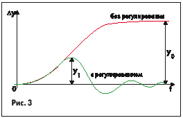
The value of R d characterizes the degree of influence of the regulator on the process, that is, the degree of reduction of the dynamic deviation in the system with and without the regulator.
The amount of overshoot depends on the type of the processed signal. When working out the step action according to the task signal, the overshoot value is determined by the formula

where the values of X m and X y are shown in Fig.4.
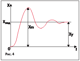
When working out the disturbing effect, the overshoot value is determined from the relation

where the values of X m and X y are shown in Fig. 5
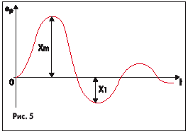
Control time- this is the time for which the controlled value in the transient process begins to differ from the steady value by less than a predetermined value b, where b is the control accuracy. The controller settings are chosen so as to provide either the minimum possible value of the total regulation time, or the minimum value of the first half-wave of the transient.
In some AP systems, an error occurs that does not disappear even after a long period of time - this static control error-e s.
For regulators with an integral component, the errors in the steady state are theoretically equal to zero, but practically insignificant errors can exist due to the presence of dead zones in the system elements.
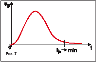
Vibration index M characterizes the magnitude of the maximum modulus of the frequency transfer function of a closed system (at the resonance frequency) and, thereby, characterizes the oscillatory properties of the system. The fluctuation index is clearly illustrated in the graph in Fig.6.

Conventionally, it is considered that the value of M = 1.5e 1.6 is optimal for industrial systems, since in this case s is provided in the range from 20 to 40%. As M increases, the oscillation in the system increases.
In some cases, the bandwidth of the system w p is normalized, which corresponds to the gain level in a closed system of 0.05. The greater the bandwidth, the greater the speed of the closed system. However, this increases the sensitivity of the system to noise in the measurement channel and increases the dispersion of the control error.
When adjusting the regulators, you can get a fairly large number of transients that meet the specified requirements. Thus, there is some uncertainty in the choice of specific values of the controller settings. In order to eliminate this uncertainty and facilitate the calculation of settings, the concept of optimal typical control processes is introduced.
There are three typical processes:

where e is the control error.

The advantages of this process include high speed (1st half-wave) with a fairly significant oscillation. In addition, the optimization of this criterion with respect to the controller settings can be performed analytically, numerically, or by modeling (on an AVM).
Typical structural scheme regulator
The automatic regulator (Fig. 10) consists of: a memory - a master device, a SU - a comparing device, an UPA - an amplifying-converting device, a BN - a setting unit.

The driving device must generate a highly stable reference signal (controller setting) or change it according to a specific program. The comparator makes it possible to compare the reference signal with the feedback signal and thereby form the value of the control error e p . The amplifying-converting device consists of a block for generating a control algorithm, a block for setting the parameters of this algorithm, and a power amplifier.
Classification of regulators
Automatic regulators are classified by purpose, principle of operation, design features, the type of energy used, the nature of the change in the regulatory action, etc.
According to the principle of operation, they are divided into regulators of direct and indirect action. Direct action regulators do not use external energy for control processes, but use the energy of the control object itself (regulated environment). An example of such regulators are pressure regulators. In automatic regulators of indirect action, an external power source is required for its operation.
According to the nature of the action, the regulators are divided into continuous and discrete. Discrete controllers, in turn, are divided into relay, digital and pulse.
According to the type of energy used, they are divided into electronic, pneumatic, hydraulic, mechanical and combined. The choice of the regulator according to the type of energy used is determined by the nature of the object of regulation and the features of the automatic system.
According to the regulation law, they are divided into two- and three-position regulators, typical regulators (integral, proportional, proportional-differential, proportional-integral and proportionally integral-differential controllers - abbreviated I, P, PD, PI and PID controllers), controllers with a variable structure, adaptive (self-tuning) and optimal controllers. Two-position regulators are widely used due to their simplicity and low cost.
According to the type of functions performed, the regulators are divided into automatic stabilization regulators, program, corrective, parameters ratio regulators and others.
Regulator type selection
The task of the designer is to choose a type of regulator that would provide the desired quality of regulation at minimum cost and maximum reliability.
In order to select the type of regulator and determine its settings, you need to know:
- Static and dynamic characteristics of the control object.
- Requirements for the quality of the regulatory process.
- Regulatory quality indicators for serial regulators.
- The nature of disturbances acting on the regulation process.
The selection of a controller type usually starts with the simplest two-position controllers and may end with self-adjusting microprocessor controllers.
Consider the quality indicators of serial regulators. Continuous controllers that implement the control laws I, P, PI and PID are assumed to be serial ones.
Theoretically, with the complication of the regulation law, the quality of the system improves. It is known that the value of the ratio of the delay to the time constant of the object c has the greatest influence on the dynamics of regulation. Efficiency of compensation of stepped perturbation by the regulator can be accurately characterized by the value of the dynamic coefficient of regulation R d , and speed - by the value of the regulation time. Theoretically, in a system with a delay, the minimum control time is t pvin =2/.
Minimum possible regulation time for various types regulators with their optimal setting is determined by Table 1.
Table 1
Guided by the table, it can be argued that the P control law provides the highest speed. However, if the gain of the P-controller KP is small (most often this is observed in systems with a delay), then such a controller does not provide high control accuracy, since in this case it is large the magnitude of the static error. If KP has a value of 10 or more, then the P-controller is acceptable, and if KP<10 то требуется введение в закон управления интегральной составляющей.
The most common in practice is the PI controller, which has the following advantages:
- Provides zero static control error.
- Fairly easy to set up, since only two parameters are set, namely the gain K P and the integration constant T i . In such a controller, it is possible to optimize K p /T i >max, which provides control with the lowest possible root mean square control error.
- It has low sensitivity to noise in the measurement channel (unlike the PID controller).
For the most critical circuits, the use of a PID controller can be recommended, which provides the highest performance in the system. However, it should be taken into account that this condition is met only with its optimal settings (three parameters are configured). With an increase in the delay in the system, negative phase shifts sharply increase, which reduces the effect of the differential component of the controller. Therefore, the quality of the PID controller for systems with a large delay becomes comparable to the quality of the PI controller. In addition, the presence of noise in the measurement channel in a system with a PID controller leads to significant random fluctuations in the control signal of the controller, which increases the dispersion of the control error. Thus, the PID controller should be chosen for control systems with a relatively low noise level and a delay in the control object. Temperature control systems are examples of such systems.
When choosing the type of controller, it is recommended to focus on the value of the ratio of the delay to the time constant in the object t /T. If t /T< 0,2, то можно выбрать релейный, непрерывный или цифровой регуляторы. Если 0,2 < t /T< 1, то должен быть выбран непрерывный или цифровой, ПИ или ПИД-регулятор. Если t /T >1, then a special digital regulator with a predictor is selected, which compensates for the delay in the control loop. However, the same regulator is recommended to be used for smaller ratios t /T.
Formula method for determining controller settings
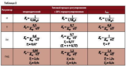
The method is used for quick approximate estimation of the values of controller tuning parameters for three types of optimal typical control processes.

The method is applicable both for static objects with self-alignment (Table 2) and for objects without self-alignment (Table 3).
Note: T, t , K oy - time constant, delay and gain of the object.
In these formulas, it is assumed that a controller with dependent settings is being tuned, the transfer function of which has the form:

K p - controller gain; T i -isodrome time (constant of integration of the controller); T d is the lead time (differentiation constant).
Calculation of settings according to the frequency characteristics of the object
There is special equipment for the experimental determination of the amplitude-phase characteristic (APC) of the control object: This characteristic can be used to calculate the settings of the PI controller, where the main criterion is to ensure the specified stability margins in the system.
It is convenient to characterize the stability margins by the system oscillation index M, the value of which in a system with a PI controller coincides with the maximum of the amplitude-frequency characteristic of a closed system. In order for this maximum not to exceed a given value, the AFC of an open-loop system should not go inside a circle with center P 0 and radius R, where

It can be proved that the optimal settings in terms of the minimum root-mean-square control error will be those at which the system with the oscillation index MJ M 1 will have the largest coefficient with the integral component, which corresponds to the condition K p /T i >min.
In this regard, the calculation of the optimal settings consists of two stages:
- Finding in the plane of the parameters K p and T i , the boundaries of the region in which the system has a given oscillatory index M 1 .
- By defining a point on the boundary of the region that satisfies the requirement K p /T i .
Calculation of settings according to the frequency characteristics of the object. Methodology for calculating the settings of the PI controller according to the AFC of the object


Experimental methods for adjusting the regulator
For a significant number of industrial control objects, there are no sufficiently accurate mathematical models that describe their static and dynamic characteristics. At the same time, carrying out experiments to remove these characteristics is very expensive and laborious.
The experimental method of adjusting regulators does not require knowledge of the mathematical model of the object. However, it is assumed that the system is installed and can be put into operation, and it is also possible to change the controller settings. Thus, some experiments can be carried out to analyze the effect of changing settings on the dynamics of the system. Ultimately, good settings are guaranteed for a given control system.
There are two tuning methods - the undamped oscillation method and the damped oscillation method.
Continuous Oscillation Method
In the operating system, the integral and differential components of the controller are turned off (T i =Ґ, T d =0), that is, the system is transferred to the control law P.
By successively increasing K p with the simultaneous application of a small jump signal of the task, undamped oscillations with a period T kp are achieved in the system. This corresponds to bringing the system to the boundary of vibrational stability. When this mode of operation occurs, the values of the critical gain of the controller K kp and the period of critical oscillations in the system T kp are fixed. When critical fluctuations appear, not a single variable of the system should go to the limit level.
According to the values of T kp and K kp, the controller settings are calculated:
- P-regulator: K p =0.55 K kp ;
- PI controller: K p =0.45 K kp ; T i =T kp /1,2;
- PID controller: K p =0.6 K kp ; T i =T kp /2; T d \u003d T kp / 8.
The calculation of the controller settings can be made according to the critical frequency of the control object itself w p. Given that the natural frequency Ґ p OS coincides with the critical oscillation frequency of a closed system with a P-controller, the values T kp and K kp can be determined from the amplitudes and period of critical oscillations proper control object.
When a closed system is brought to the boundary of vibrational stability, the oscillation amplitude may exceed the permissible value, which in turn will lead to an emergency at the facility or to the production of defective products. Therefore, not all control systems for industrial facilities can be brought to a critical mode of operation.
Damped Oscillation Method
The use of this method allows you to adjust the controllers without bringing the system to critical operating modes. Just as in the previous method, for a closed system with a P-controller, by successively increasing KP, a transient process of processing a rectangular pulse according to a reference or disturbance signal with a damping decrement D=1/4 is achieved. Further, the period of these oscillations T k and the values of the constants of integration and differentiation of the controllers T i ,T d are determined.
- For PI controller:T i =T k /6;
- For PID controller: T i =T k /6;T d =T k /1.5.
After setting the calculated values of T i and T d on the controller, it is necessary to experimentally refine the value of K P to obtain the damping factor D=1/4. For this purpose, an additional adjustment of K P for the selected control law is performed, which usually leads to a decrease in K P by 20–30%. Most industrial control systems are considered well tuned if their damping factor D is 1/4 or 1/5.
Regulation in the presence of noise
The presence of high-frequency noise components in the measuring signal leads to random oscillations of the system actuator, which increases the dispersion of the control error and reduces the control accuracy. In some cases, strong noise components can lead the system to an unstable mode of operation (stochastic instability).
In industrial systems, measuring circuits often contain noise associated with the mains frequency. In this regard, an important task is the correct filtering of the measuring signal, as well as the choice of the desired algorithm and parameters of the controller. For this, high-order low-frequency filters (5–7) are used, which have a large slope of the slope. They are sometimes built into normalizing converters.
Thus, the main task of the regulator is to compensate for low-frequency disturbances. In this case, in order to obtain a minimum dispersion of the control error, high-frequency noise must be filtered out. However, in general case, this problem is contradictory, since the perturbation and noise spectra can be superimposed on each other. This contradiction is resolved using the theory of optimal stochastic control, which makes it possible to achieve good speed in the system with the minimum possible dispersion of the control error. To reduce the effect of interference in practical situations, two methods are used based on:
- decrease in the controller gain K p , that is, in fact, the transition to integral law regulation, which is insensitive to noise;
- filtering the measured signal.
Methods for setting up two-coupled control systems
Of the total number of control systems, about 15% are doubly connected control systems (Fig. 11). In such systems, even in the presence of a stable battery life two regulators, the whole system can become unstable due to the action of cross-coupling in the control object.
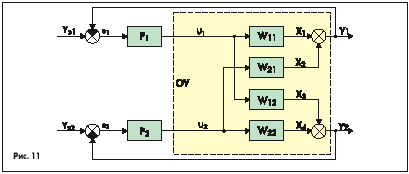
The control object in a doubly connected system is represented in the P-canonical form. The convenience of this representation lies in the fact that by active experiment it is possible to determine all the transfer functions for the corresponding channels. Intermediate signals x 1 , x 2 , x 3 , x 4 are usually not available for measurement, so the control is carried out according to the output vector Y:
In practice, a fairly large number of systems are doubly connected. For an objective adjustment of the regulators of two-connected systems, a quality criterion of the form is formed:
where y 1 and y 2 are the weight (penalty) coefficients, J1 and J 2 are the quality criteria of the first and second circuits.
By redistributing the weight coefficients y 1 and y 2, it is possible to single out a more important circuit, the quality of control processes in which should be higher. For example, if the first circuit should provide higher accuracy, then y 1 needs to be increased.
The task of adjusting the controller is to provide the minimum value of J 0 of the system for given y 1 and y 2, where

Consider various methods regulator settings in two-connected systems.
Regulator Offline Method
In this case, the adjustment of the regulators P 1 and P 2 is carried out sequentially, without taking into account the mutual influences of the circuits. The setup procedure is as follows:
- regulator P 2 is switched to manual mode;
- the regulator P 1 is adjusted so that the criterion J 1 is minimal;
- the adjusted regulator P 1 is turned off and the regulator P 2 is turned on;
- adjusted P 2 , providing a minimum of J 2 ;
- Both controls are active.
- there is a small mutual influence of the contours;
- the speed of one circuit is much higher than the other (the circuits are separated by frequencies);
- in cross-links, one of the transfer functions has a transfer coefficient significantly less than the other, that is, one-sided influence is observed.
Regulators iterative tuning method
This method is similar to the previous one, but here the regulators P 1 and P 2 are repeatedly tuned (successive tuning) in order to ensure the minimum value of the quality criterion J 0 of the entire system.
It should be taken into account that only the method of iterative tuning of the controllers ensures the high-quality operation of a doubly connected system even in the presence of strong cross-couplings. This is explained by the fact that the optimization of the quality criterion J 0 of the system occurs when P 1 and P 2 are enabled.
This method often used in analog and digital modeling of doubly connected systems, since in real conditions it is very laborious.
Method of Analytical Design of Regulators
This method allows you to synthesize a multidimensional controller that takes into account the relationship of variables in the control object in its structure. Synthesis is carried out using methods of the theory of optimal or modal control when describing an object in the state space.
The block diagram of the optimal state controller containing the observing device is shown in Fig.12. The scheme contains the following elements: H - observer, OS - control object, MOU - module of the control object, OPC - optimal state controller, E H - observation error, X M - state vector of the model, X set - task vector, U - input vector OA, Y - OA output vector, Y M - model output vector.
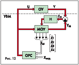
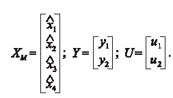
The optimal state controller, being the most perfect type of controller, requires the measurement of all components of the object's state vector. To obtain their estimates (x), a dynamic model of the object (digital or analog) is used, connected in parallel to the original op-amp. To ensure the equality of movements in the real object and the model, an observer is used, which, by comparing the movements of the vectors Y and Y M, ensures their equality (E H >0). The parameters of the state controller are calculated by methods of analytical design of controllers by minimizing the integral quadratic quality criterion
![]()
where Q and R are the penalty matrices (weights) for the components of the state vector and the control vector.
The publication is based on a course of lectures given by Professor V.M. Mazurov at the Department of ATM of Tula State University
