It happens like this, from work in the heat you drop by the post office, pick up the package, come home tired and forget about it for a few days ... Sometimes you remember - well, what's special - dc-dc converters like dc-dc converters. Let it lie down, then unpack it. Yesterday, late at night, I remembered it all the same and did not put it off “for later”. He opened the package, a rather voluminous bundle, tightly wrapped with a "pimple" fell out of it.
there are large photos without spoilers
Some problems in working with electronics, it is not difficult to modify or bring devices to become affordable. If we know the principles and limitations of these devices. Since the project is proposed at this time, will bring batteries of 5 volts connected through an electronic circuit called a DC converter to increase the voltage to have a higher value of 9 volts instead of a battery of 6 series connected.
It can also increase the voltage from a 3 volt battery to 9 volts, as well as the original circuit, and this will increase the current. To change the input voltage that comes from the battery pack 1 or 2. How it works. - When connecting a battery to input terminal 2, which can be one battery pack or two pieces. When starting the low voltage circuit. This low voltage circuit is started, the feedback voltage is biased to the transistors inside the integrated circuit.

In a bundle - they are darlings, 4 pcs.
In fact, I didn’t originally intend to write about them.
But then, looking into the package, I was pleasantly surprised.
That would seem like a trifle, a penny order, one of the lowest prices for these converters, but no, the seller was not too lazy to attach a souvenir gift here. 

And with a probability of 99.9%, it will not be useful to me anywhere, but all the fuss and worries of a hard day have been taken away. Nicely. And the next time I go to Ali to look for something, I will be one of the first to look for this seller.
And with this post I want to say THANK YOU to the seller! For uplifting, positive emotions. 
Here you go. Emotions were given free rein, let's move on to boring numbers.
Which has a copper pattern, which is shown in Figure 3, represents the position of the device. Then, if you insert a battery, inject two packs or 3 volts into it. to disconnect the jumper. This will increase to the current on the jumper cables. D.C no load depends on the difference between the input and output voltages. When the values are close, the quiescent current can be less than one milliamp, but when they are very separate values, it can reach tens of milliamps.
Typical efficiency is 80% to 95%, depending on input voltage, output voltage and load. Eight small holes at the ends of the plate are arranged in 2.54mm pitch, compatible with seamless breadboards, connectors and other prototyping elements, the pins of the 9 × male connector strip can be welded in these holes. Alternatively, you can weld the 2-pin terminal blocks included included, for two pairs of large holes at the ends of the board. For a more compact installation, cables can be soldered directly to the plate.
Declared performance characteristics
- Input voltage: 0.9V-5V,
- Maximum efficiency: 96%,
- Output current when powered by one AA element: up to 200mA-300mA,
- ========//========= from two AA elements: 500mA-600mA.
Measurements.
To begin with, let's measure consumption without load when powered by 1 AA battery, 2 and 3, as the attentive reader has already guessed, batteries. Akki already worked, the voltage of each is about 1.25V.
The principle of operation of the device
Mounting holes are located in opposite corners. The output voltage can be adjusted with a multimeter and a light load. Turning the potentiometer clockwise increases the output voltage. The output voltage can be affected if the screwdriver touches the potentiometer, so the output must be measured without any contact with the potentiometer.
Warning: You must be careful not to use an input voltage that exceeds the output voltage value, so it is recommended to adjust the output voltage with an input voltage that is below the output range. The absolute limit of the input voltage is approximately twice the value of the output voltage. For example, if the output is 10V, exceeding 20V at the input could damage the regulator. Once the input exceeds the output limit, the output voltage will rise with the input voltage as the input is connected to the output via an inductor and a diode.
- We see that when powered by:
- 1st AA current consumption is almost 0.4mA
- 2 AA current consumption is almost 0.8mA
- 3-AA current consumption is almost 1.9mA

How to reduce the consumption of the converter itself to 30 μA I will tell and show a little lower.
The consumption of the converter at idle is certainly an interesting indicator, but it’s much more interesting how it behaves when powered, for example, by a USB LED lamp for $ 0.67, “like xiaomi”.
Let's see.
The lamp, when powered by a full-fledged 5-volt source (sorry for the tautology), consumes 200mA.
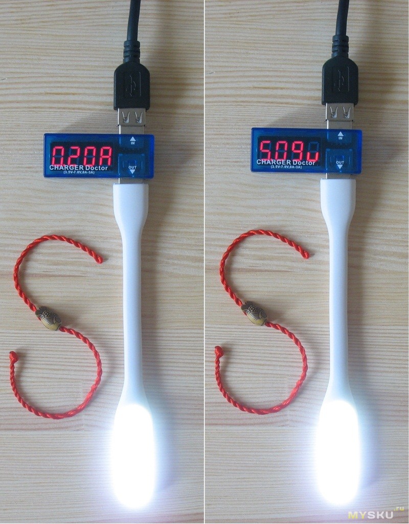
Now we turn on the Charger Doctor at the output of the converter, turn on the lamp in the Charger Doctor, power the structure with a number of AA batteries equal to from 0 to 3.
We love the results.
The results of testing with the number of batteries equal to 0, for obvious reasons, were not included in the review.
First, the output voltage:

Now currents:
The photo session of current measurements was carried out under brighter lighting, so in the photographs it seems that the lamp shines differently, in fact it is the same.
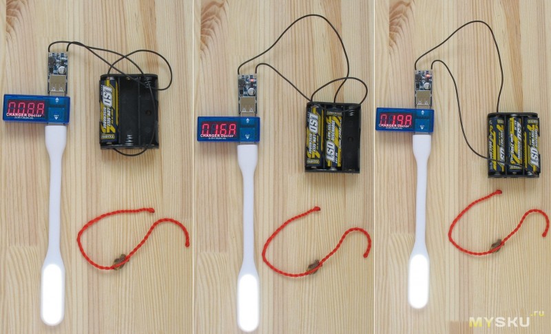
Table summary:
The measurements are certainly not comprehensive, but the trend can be caught.
It can be seen that with a more or less significant load and a low input voltage, there will be no 5 volts at the output. However, as well as the declared current. As I see it, the best option for powering this converter is a lithium battery, then you can expect a relatively stable 5V output.
A curious reader can ask a completely logical question: “Well, where else can it be applied?
And I got ready, I have the answer here, in the spoiler -
one of the possible applications.
Element base selection
Typical efficiency and output current. As shown in the graphs above, these switching regulators are 80% to 95% efficient for most combinations of input voltage, output voltage, and load. The maximum output current that can be achieved is approximately proportional to the ratio of the input and output voltages. If the input current exceeds the current limit of the switch, 5A, the output voltage will start to drop. In addition, the maximum output current may be affected by other factors including temperature environment, airflow and heat dissipation.
And this option was LED lamp with motion sensor.
Another picky reader (or maybe this is the same curious one) may quite reasonably object: “Excuse me, why “collective farm” this device, when the floor of aliexpress and a small cart of online stores are littered with similar lamps for $ 4 -5 $ ?!“ and it will rights.
If I just needed to illuminate a part of the room at night when someone appeared in the sensor's coverage area, I would definitely buy it there.
But in my case, I really wanted to relieve the itching in my hands, to check the concept and feasibility of using such a converter to power an autonomous device that works _without turning off the power_. Appearance, aesthetics, thoughtful design were not decisive factors in the manufacturing process.
For this purpose, it came in handy:
- A lithium battery extracted from a laptop battery that has lost all its former agility and turned into a pile of spare parts, 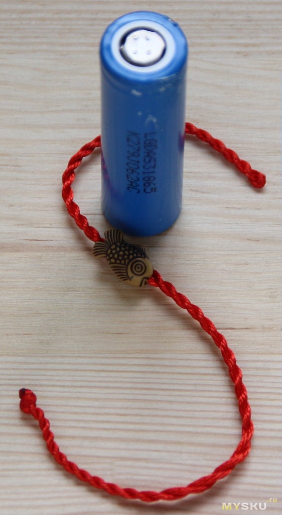
- LED Strip Light highlighting the matrix of the same unfortunate, 
- Motion sensor, type HC-SR501, 
- Photoresistor GL5528, 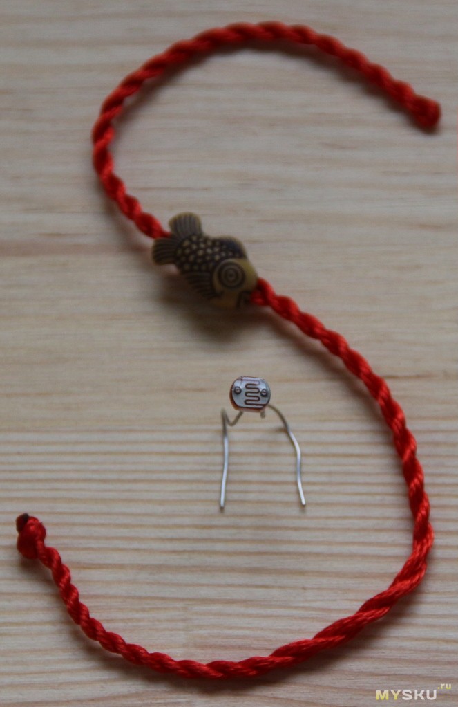
- connector type PBS, from which we carefully separate 3 contacts, 
- NPN transistor type BC546,547,847 or similar. I installed 2n3904. 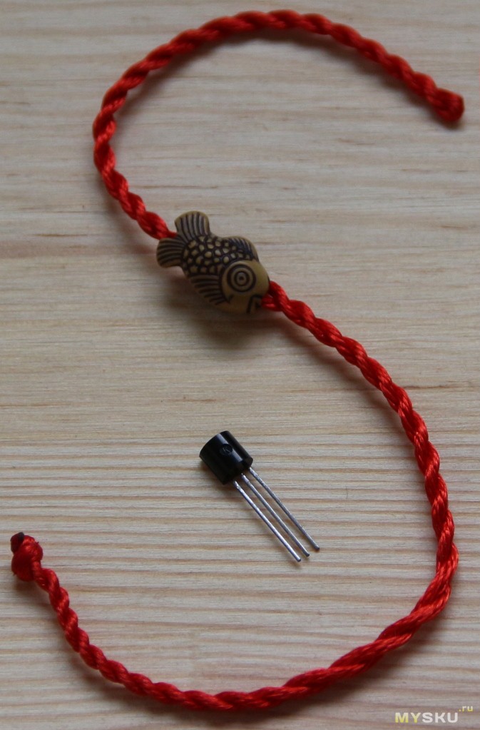
- Resistor 39 Ohm, 
- A little wires, patience, free time and of course the hero of this review is a dc-dc converter, the photo of which in the plural and from various angles was higher, so I will not repeat
During normal operation this regulator can get hot enough to burn. Be careful when handling this product or other components connected to it. You can do it as you say with series resistance if the consumption of what you are going to connect is constant and you don't mind losing a quarter of the energy as heat. If what you are going to connect has very low consumption, if possible. If the consumption is really low, even if it's not constant, you can make a voltage divider.
Before everything works out, let me clarify the nuances of some details.
Motion sensor, type HC-SR501. Fires when there is movement of a heat-radiating object within its line of sight. Has two tuning resistors, with which you can set the trigger threshold and the time to keep the output on after the disappearance of the factor that caused the trigger. The yellow jumper selects one of the two operating modes:
1 - The sensor has worked, the output has been activated, the countdown of the time set by the resistor has started, regardless of the presence of heat movement in the sensor's visibility zone, the timer has worked out - the output has been deactivated. After the blocking time has passed (the sensor does not respond to influences), if there is movement, it will work again.
2 - The sensor has been triggered, the output is activated, the time countdown has started, if there is movement in the sensor's visibility zone, the timer restarts until the movement disappears, the movement has stopped, the time is up, the output is turned off.
The position of the jumper shown here in the photo corresponds to the first mode of operation, then in the finished device - to the second.
In order for the sensor not to work during daylight hours, you need to solder the photoresistor to the place provided for its installation - circled in red. 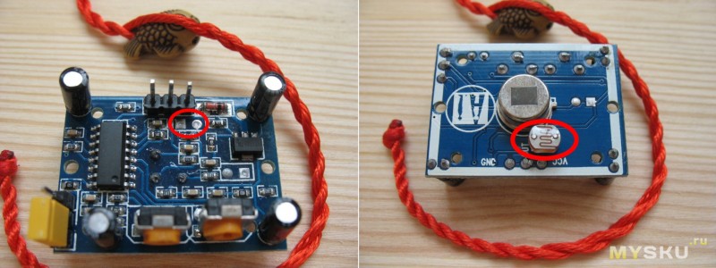
The voltage divider solution is similar, you need two resistors one is 3 times bigger than the other and you place them in series and the plugs are 12V then you connect your device to the ends more resistance. This works if the connected device's consumption is very low. You can use, for example, one of 60 and the other of 180 ohms, that is, two half watts, at least a lesser danger. Do not use these systems to connect devices that consume a lot, because the resistance heats up proportionally and can be ignited.
I decided to use 5 LEDs from the matrix backlight tape connected in parallel for the lamp. Looking ahead, I’ll say that in this form, their total consumption, limited by a 39Ω resistor, is about 48mA, i.e. less than 10mA per LED. It is clear that for good it is necessary to put a current-limiting resistor on each LED, but in this design this is redundant. In addition, the LEDs work at least 30 percent below their rated load, almost do not heat up and are securely held on the case with double-sided tape. 
If you have questions send me Additional information. First you use ohm's law according to the receiver and you get 90 ohms. The operational amplifier is one of the most used components in the world of electronics. Conceptual simplicity and versatility are the keys to its wide and varied use. Initially, op amps were mainly used in discrete compound circuits to implement filters or amplify assemblies. They are currently being reused or redesigned as the base units are easily integrated into very complex systems, usually in building blocks. medium difficulty such as transducers, synthesizers, filters, etc.
The turn has come to the converter. As we remember, by itself, when powered by 3 AAs (approximately as from the 1st not fully charged lithium), it consumes almost 2 mA. I think that this is a lot for a device that should be in working order for as long as possible.
You can deal with this by soldering the LED, or its current-limiting resistor. 
In such a simple way, the consumption of the dc-dc converter has decreased to 30 μA.
The scope that uses this element goes from measuring devices to all kinds of circuits for computers and telecommunications, passing through various electrical appliances, cars - it can be said without exaggeration that their use is almost universal. In these applications, they are an integral part of most fundamental electronic circuits studied at the department, such as analog-to-digital and digital-to-analog converters, oscillators, phase lock grids, analog filters, optoelectronic circuits and peripheral communication devices.
It's time to put everything together.
Since the signal from the motion sensor controller has a level of 3.3V and is fed to the output pin of the connector through a 1kΩ resistor, it is impossible to connect LEDs directly to it. No, of course you can connect, but they will not shine. In order for the LEDs to burn, it is necessary to ensure that sufficient current flows through them for this process. The key on the transistor will perfectly cope with this task.
Schematically it looks like this: 
This is because the amplifier is not being driven or positively driven, or that the output voltage is trying to overcome the loop supply ends while leaving a linear operating area. One of the following expressions must be true in these two zones.
Typically, this circuit is used to compare two signals and generate bits with information corresponding to the relative order of the voltage values of the signals. Usually one of the voltage levels to be compared is constant pressure. The chain diagram shown in the following figure is a simple as well as practical circuit.
After several strokes of a hacksaw, drill, file, soldering iron and heat gun, this design turned out: 
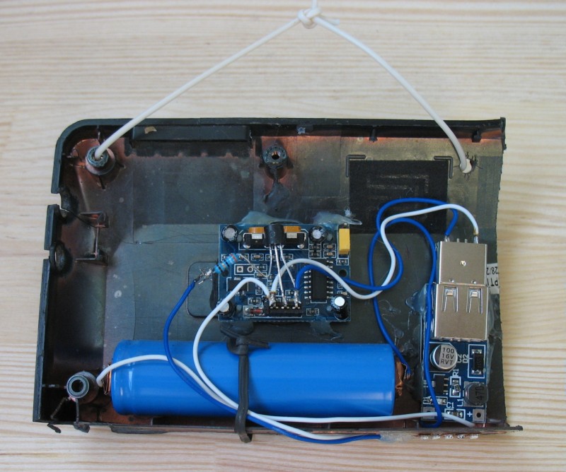
The total consumption in standby mode is about 0.4mA, when triggered - 80-82mA.
Amplifier without inverter
This mount is used to scale the signal. The input signal is multiplied by a negative gain, so the polarity is inverted. This assembly is similar to the previous assembly, however the input signal is then multiplied by a positive gain so that the polarity is not inverted. Thus, until the output voltage reaches the supply voltage, the following equations apply.
The integrator circuit is a fundamental building block in the implementation of filters. This assembly can be analyzed very simply when compared to a transducer. Thus, the output voltage is proportional to the integral of the input voltage. Thus, the output voltage is proportional to and derived from the input voltage over time.
What can I say ... The device succeeded. Hung from the ceiling and has been working for almost a month. During the evening it turns on several times. The voltage on the battery dropped from the original by a little less than 0.1V. 
The picture on the wall was painted by the wife
In general, collected, hung and forgot. Only sometimes you remember - well, what's special - dc-dc converters, like dc-dc converters.
This assembly is used to add two or more signals. Thus, provided that the output voltage does not reach the supply voltage, the following equations are valid. The behavior is very similar to that of a converter. As it turns out, the output is the weighted sum of the input voltages.
Thus, the following equations apply. The output is a weighted subtraction of the input voltages. This function can be used in communication systems to avoid possible problems switching due to the existence of noise superimposed on the input signal. The hysteresis zone prevents fluctuations in the output of the comparator caused by noise affecting the region in which the switch occurs, because it creates a margin of protection for this noise. The following figure shows the critical area.
With an eye on the input voltage, I recommend the converters boldly, the seller strongly :)
I plan to buy +45 Add to favorites Liked the review +57 +107Low Power Converter to power the load 9 volts from Li-ion battery 3.7 volts
The first wave is a noiseless sine wave applied at the comparator input. The second wave represents the same input with high frequency noise. The output of a normal comparator will be switching due to noise in the zero volt channel.
Negative reverse assemblies
The dimension of the hysteresis zone must take into account the predicted maximum noise amplitude, since a very wide margin introduces a significant delay in switching. These types of circuits are stable and usually operate outside the saturation region.
Collections with positive feedback
Another example of positive feedback is the Schmitt-initiated comparator presented earlier. This circuit has two stable states and a hysteresis zone, sometimes called a bistable circuit.Some modern low-power devices consume a very small current (several milliamps), but for their power they require too exotic a source - a 9 V battery, which is also enough for a maximum of 30 ... 100 hours of device operation. It looks especially strange now, when Li-ion batteries from various mobile gadgets are almost cheaper than the batteries themselves - batteries. Therefore, it is natural that a real radio amateur will try to adapt the batteries to power his device, and will not periodically look for "antique" batteries.
The output voltage error associated with this limitation is inversely proportional to the gain value. Thus, they are usually sized to achieve a good compromise between output impedance and power consumption. This limitation often determines the maximum resolution that can be obtained.
Ideally, the input terminals have a very high impedance, similar to the input impedance of a voltmeter. This feature makes them obvious choices when constructing interface circuits, since they do not significantly change the operation of the controlled circuit. The ability to supply current without degrading the output voltage results in a low output impedance.
If we consider a conventional (and popular) multimeter as a low-power load. M830, powered by an element of the "Korund" type, then to create a voltage of 9 V, at least 2-3 batteries connected in series are needed, which does not suit us, they simply will not fit inside the device case. Therefore, the only way out is to use one battery and a boost converter.
The basic topology of a single-stage op-amp, as shown in the following figure, consists of a differential pair consisting of two transistors with connected emitters. This type of configuration is commonly referred to as a resistive load and is presented in front. The configuration shown in the previous two examples is a passive load.
Now let's analyze the output voltage in any of the presented circuits. This method is often used in active filters and has several advantages over using only one of the outputs. The considerations made in the previous circuits about the current and state of the transistors of a differential pair are equally valid for this circuit.
Element base selection
The simplest solution is to use the 555 type timer (or its 7555 CMOS version) in pulse converter(capacitive converters are not suitable, we have too much difference between the input and output voltages). An additional "plus" of this microcircuit, it has an open-collector output, moreover, a sufficiently high-voltage one capable of withstanding voltages up to +18 V at any operating supply voltage. Thanks to this, it is possible to assemble a converter from literally a dozen cheap and common parts (Fig. 1.6).

Rice. 1.6. Diagram of a simple converter
Pin 3 of the chip is a normal two-state output, it is used in this circuit to maintain generation. Pin 7 is an open collector output capable of withstanding overvoltage, so it can be connected directly to the coil, without a transistor follower. The reference voltage input (pin 5) is used to regulate the output voltage.
The principle of operation of the device
Immediately after the supply voltage is applied, the capacitor C3 is discharged, the current through the zener diode VD1 does not flow, the voltage at the REF input of the microcircuit is 2/3 of the supply voltage, and the duty cycle of the output pulses is 2 (that is, the pulse duration is equal to the pause duration), the capacitor C3 charges at maximum speed . Diode VD2 is needed so that the discharged capacitor C3 does not affect the circuit (does not reduce the voltage at pin 5), resistor R2 "just in case", for protection.
As this capacitor charges, the zener diode VD1 begins to open slightly, and the voltage at pin 5 of the microcircuit rises. From this, the pulse duration decreases, the pause duration increases, until dynamic equilibrium occurs and the output voltage stabilizes at a certain level. The value of the output voltage depends only on the stabilization voltage of the zener diode VD1 and can be up to 15 ... 18 V at a higher voltage, the microcircuit may fail.
About details
Coil L1 is wound on a ferrite ring. K7x5x2 (outer diameter - 7 mm, inner - 5 mm, thickness - 2 mm), approximately 50 ... 100 turns with a wire with a diameter of 0.1 mm. You can take a larger ring, then the number of turns can be reduced, or you can take an industrial inductor with an inductance of hundreds of microhenries (µH).
The 555 microcircuit can be replaced with the domestic analogue K1006VI1 or with the CMOS version 7555 - it has less current consumption (the battery will "last" a little longer) and a wider operating voltage range, but it has a weaker output (if the multimeter requires more than 10 mA, it may not to give such a current, especially at such a low supply voltage) and she, like all CMOS structures, "does not like" the increased voltage at its output.
Device Features
The device starts working immediately after assembly, the whole setting consists in setting the output voltage by selecting the zener diode VD1, while a 3.1 kΩ resistor (load simulator) must be connected to the output in parallel with the capacitor C3 (load simulator), but not a multimeter!
It is forbidden to turn on the converter with an unsoldered zener diode, then the output voltage will be unlimited and the circuit can "kill" itself. You can also increase the operating frequency by reducing the resistance of the resistor R1 or capacitor C1 (if it operates at an audio frequency, a high-frequency squeak is heard). If the length of the wires from the battery is less than 10 ... 20 cm, a filtering power supply capacitor is optional, or you can put a capacitor with a capacity of 0.1 uF or more between pins 1 and 8 of the microcircuit.
Identified shortcomings
Firstly, the device contains two oscillators (one master oscillator of the ADC chip - analog-to-digital converter of the device, the second generator of the converter) operating at the same frequencies, that is, they will affect each other (frequency beat) and the measurement accuracy will seriously deteriorate.
Secondly, the frequency of the converter generator is constantly changing depending on the load current and battery voltage (because there is a resistor in the POS - positive feedback circuit, and not a current generator), so it becomes impossible to predict and correct its influence. Specifically for a multimeter, one common oscillator for the ADC and a converter with a fixed operating frequency would be ideal.
The second version of the converter
The circuit of such a converter is slightly more complicated and is shown in Fig. 1.7.

Rice. 1.7. Schematic of the converter with a fixed operating frequency
A generator is assembled on the DD1.1 element, through the capacitor C2 it clocks the converter, and through C5 - the ADC chip. Most inexpensive multimeters are based on the ICL7106 double-integration ADC or its analogues (40 pins, 3.5 characters on the display), to clock this microcircuit, you just need to remove the capacitor between pins 38 and 40 (unsolder its leg from pin 38 and solder to the pin 11DD1.1). Thanks to feedback through a resistor between pins 39 and 40, the microcircuit can be clocked even with very weak signals with an amplitude of a fraction of a volt, so 3-volt signals from the DD1.1 output are quite enough for its normal operation.
By the way, in this way it is possible to increase the measurement speed by 5 ... 10 times - simply by increasing the clock frequency. The measurement accuracy practically does not suffer from this; it worsens by a maximum of 3 ... 5 units of the least significant digit. It is not necessary to stabilize the operating frequency for such an ADC, so a conventional RC oscillator is quite sufficient for normal measurement accuracy.
On the elements DD1.2 and DD1.3, a waiting multivibrator is assembled, the pulse duration of which, using the transistor VT2, can vary from almost 0 to 50%. In the initial state, at its output (pin 6) there is a "logical unit" (high voltage level), and the capacitor C3 is charged through the diode VD1. After the arrival of a triggering negative pulse, the multivibrator "tip", a "logical zero" (low voltage level) appears at its output, blocking the multivibrator through pin 2 of DD1.2 and opening the transistor VT1 through the inverter on DD1.4 In this state, the circuit will be until then until the capacitor C3 is discharged - after which the "zero" at pin 5 of DD1.3 will "tip" the multivibrator back into the standby state (by this time C2 will have time to charge and there will also be "1" at pin 1 of DD1.1), transistor VT1 will close , and the coil L1 will be discharged to the capacitor C4. After the arrival of the next pulse, all of the above processes will repeat again.
Thus, the amount of energy stored in the coil L1 depends only on the discharge time of the capacitor C3, that is, on how strongly the transistor VT2 is open, which helps it to discharge. The higher the output voltage, the stronger the transistor opens; thus, the output voltage is stabilized at a certain level, depending on the stabilization voltage of the zener diode VD3.
Used to charge the battery the simplest converter on an adjustable linear stabilizer DA1. You only have to charge the battery, even with frequent use of the multimeter, only a couple of times a year, so putting a more complex and expensive one here switching regulator it makes no sense. The stabilizer is set to an output voltage of 4.4 ... 4.7 V, which is lowered by 0.5.0.7 V by the VD5 diode to standard values for a charged lithium-ion battery (3.9 ... 4.1 V). This diode is needed so that the battery is not discharged through DA1 offline. To charge the battery, you need to apply a voltage of 6 ... 12 V to the XS1 input and forget about it for 3 ... 10 hours. With a high input voltage (more than 9 V), the DA1 chip gets very hot, so you need to either provide a heat sink or lower the input voltage.
As DA1, you can use 5-volt stabilizers KR142EN5A, EN5V, 7805 - but then, to dampen the "excess" voltage, VD5 must be made up of two diodes connected in series. Transistors in this circuit can be used in almost any n-p-n structures, KT315B are here only because the author has accumulated too many of them.
KT3102, 9014, VS547, VS817, etc. will work normally. Diodes KD521 can be replaced with KD522 or 1N4148, VD1 and VD2 should be high-frequency ideal BAV70 or BAW56. VD5 any diode (not Schottky) of medium power (KD226, 1N4001). The VD4 diode is optional, it’s just that the author had too low-voltage zener diodes and the output voltage did not reach the minimum 8.5 V, and each additional diode in direct connection adds 0.7 V to the output voltage. The coil is the same as for the previous circuit (100. ..200 µH). The scheme for finalizing the multimeter switch is shown in fig. 1.8.
Rice. 1.8. Wiring diagram multimeter switch improvements
The positive terminal of the battery is connected to the central track-ring of the multimeter, but we connect this ring to the "+" of the battery. The next ring is the second contact of the switch, and it is connected to the multimeter circuit elements in 3-4 tracks. These tracks on the opposite side of the board must be broken and connected together, as well as with the +9 V output of the converter. The ring is connected to the +3 V converter power bus. Thus, the multimeter is connected to the output of the converter, and with the multimeter switch we turn the power of the converter on and off. We have to go to such difficulties due to the fact that the converter consumes some current (3 ... 5 mA) even with the load turned off, and the battery will be discharged by such a current in about a week. Here we turn off the power of the converter itself, and the battery will last for several months.
A device correctly assembled from serviceable parts does not need to be configured, sometimes you only need to adjust the voltage with resistors R7, R8 (charger) and a zener diode VD3 (converter).

Rice. 1.9 PCB options
The board has the dimensions of a standard battery and is installed in the appropriate compartment. The battery is placed under the switch, usually there is enough space, you must first wrap it with several layers of electrical tape or at least tape.
To connect the charger connector in the multimeter case, you need to drill a hole. The pinout for different XS1 connectors is sometimes different, so you may need to modify the board a little.
So that the battery and the converter board do not "dangle" inside the multimeter, they need to be pressed with something inside the case.
See other articles section.


