Modern fluorescent light bulbs are a real find for economical consumers. They shine brightly, last longer than incandescent bulbs and consume much less energy. At first glance, there are only pluses. However, due to the imperfection of domestic power grids, they exhaust their resource much ahead of schedule declared by the manufacturers. And often they do not even have time to "cover" the cost of their acquisition.
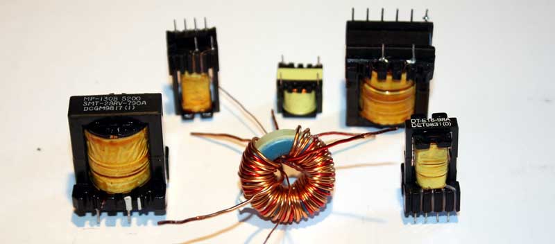
But do not rush to throw out the failed "housekeeper". Given the considerable initial cost of fluorescent light bulbs, it is advisable to “squeeze” the maximum out of them, using all their possible resources to the last. Indeed, right under the spiral, a compact high-frequency converter circuit is installed in it. For a knowledgeable person, this is a whole “Klondike” of various spare parts.
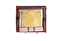
Disassembled lamp
General information
Battery
In fact, such a circuit is an almost ready-made switching power supply. It lacks only an isolation transformer with a rectifier. Therefore, if the flask is intact, you can, without fear of mercury fumes, try to disassemble the case.
By the way, it is the lighting elements of light bulbs that most often fail: due to resource burnout, merciless operation, too low (or high) temperatures, etc. The internal boards are more or less protected by a hermetically sealed case and parts with a margin of safety.
We advise you to save up a certain number of lamps before starting repair and restoration work (you can ask around at work or with friends - usually there is enough such good everywhere). After all, it is not a fact that all of them will be maintainable. In this case, it is the performance of the ballast (that is, the board built inside the light bulb) that is important to us.
You may have to dig a little for the first time, but then in an hour you will be able to assemble a primitive power supply for devices that are suitable in terms of power.
If you plan to create a power supply, choose models of fluorescent lamps more powerful, starting from 20 watts. However, less bright light bulbs will also be used - they can be used as donors of the necessary details.
And as a result, from a couple of burnt housekeepers, it is quite possible to create one completely capable model, whether it be a work light, a power supply or a battery charger.
Most often, self-taught masters use housekeeper ballast to create 12-watt power supplies. They can be connected to modern LED systems, because 12 V is the operating voltage of most of the most common household appliances, including lighting.
Such blocks are usually hidden in furniture, so appearance node doesn't really matter. And even if outwardly the craft turns out to be sloppy - it's okay, the main thing is to take care of maximum electrical safety. To do this, carefully check the created system for operability, leaving it to work in test mode for a long time. If power surges and overheating are not observed, then you did everything right.
It is clear that you will not extend the life of an updated light bulb much - anyway, sooner or later the resource is exhausted (the phosphor and the filament burn out). But you must admit, why not try to restore the failed lamp within six months or a year after purchase.
We disassemble the lamp
So, we take a non-working light bulb, we find the junction of the glass bulb with the plastic case. Gently pry the halves with a screwdriver, gradually moving along the "belt". Usually these two elements are connected by plastic clips, and if you are going to use both parts in any other way, do not apply great effort- a piece of plastic can easily break off, and the tightness of the light bulb housing will be broken.
After opening the case, carefully disconnect the contacts going from the ballast to the filaments in the bulb, because. they block full access to the board. Often they are simply tied to the pins, and if you do not plan to use the failed bulb anymore, you can safely cut off the connecting wires. As a result, you should see something like this scheme.
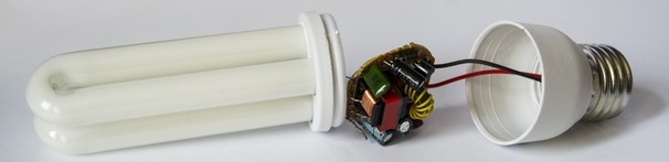
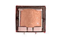
Lamp disassembly
It is clear that the designs of lamps from different manufacturers may differ in "stuffing". But general scheme and the basic constituent elements have much in common.
Then you need to scrupulously inspect each part for blisters, breakdowns, make sure that all elements are soldered securely. If any of the parts burned out, it will be immediately visible by the characteristic soot on the board. In cases where no visible defects are found, but the lamp is not working, use the tester and “ring out” all the elements of the circuit.
As practice shows, resistors, capacitors, dinistors most often suffer due to large voltage drops that occur with unenviable regularity in domestic networks. In addition, frequent flicking of the switch has an extremely negative effect on the duration of the operation of fluorescent bulbs.
Therefore, in order to extend their operating time as long as possible, try to turn them on and off as little as possible. The pennies saved on electricity will eventually result in hundreds of rubles to replace a burnt-out light bulb ahead of time. .

Disassembled lamps
If, as a result of the initial inspection, you have identified burn marks on the board, swelling of parts, try replacing the failed blocks by taking them from other non-working donor bulbs. After installing the parts, once again “ring” all the components of the board with the tester.
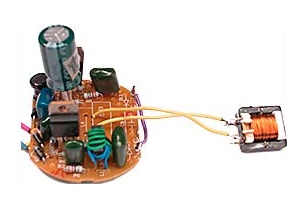
By and large, from the ballast of a non-working fluorescent light bulb, you can make impulse block power supply corresponding to the original lamp power. As a rule, low-power power supplies do not require significant modifications. But over blocks of greater power, of course, you have to sweat.
To do this, it will be necessary to slightly expand the capabilities of the native choke by providing it with an additional winding. You can adjust the power of the created power supply by increasing the number of secondary turns on the inductor. Do you want to know how to do it?
Preparatory work
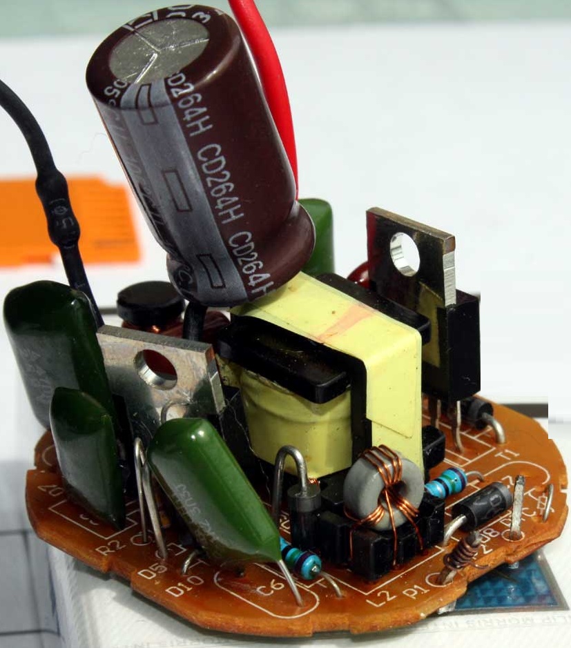
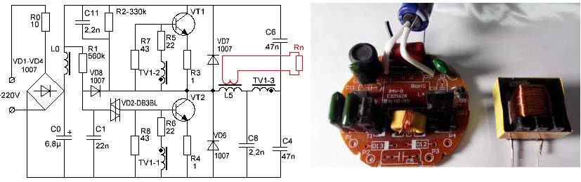
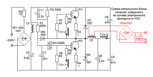
As an example, below is a diagram of a Vitoone fluorescent light bulb, but in principle the composition of boards from different manufacturers does not differ much. In this case, a light bulb of sufficient power is presented - 25 watts, it can make an excellent 12 V charging unit.
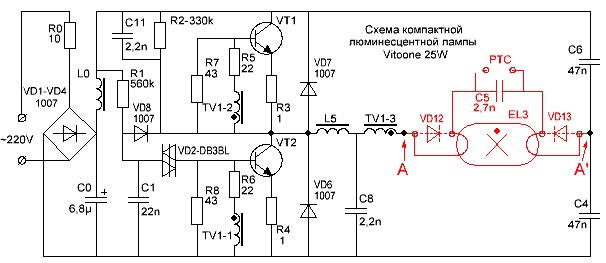
Vitoone 25W lamp circuit

Power supply assembly
The red color in the diagram indicates the lighting unit (i.e., the bulb with filaments). If the threads in it are burned out, then we will no longer need this part of the light bulb, and we can safely bite off the contacts from the board. If the light bulb still burned before the breakdown, albeit dimly, you can then try to revive it for a while by connecting it to the working circuit from another product.
But it's not about that now. Our goal is to create a power supply from a ballast extracted from a light bulb. So, we delete everything that is between points A and A´ in the above diagram.
For a low-power power supply (approximately equal to the original one of the donor bulb), only a small alteration is enough. A jumper must be installed in place of the remote lamp assembly. To do this, simply wind a new piece of wire to the released pins - at the place of attachment of the former filaments of an energy-saving light bulb (or to the holes for them).
In principle, you can try to slightly increase the generated power by providing an additional (secondary) winding to the choke already on the board (it is indicated on the diagram as L5). Thus, its native (factory) winding becomes primary, and another layer of secondary provides the same power reserve. And again, it can be adjusted by the number of turns or the thickness of the wound wire.
Connecting the power supply
But, of course, it will not be possible to significantly increase the initial capacity. Everything depends on the size of the "frame" around the ferrites - they are very limited, because. originally intended for use in compact lamps. Often it is possible to apply turns in only one layer, eight to ten will be enough for a start.
Try to apply them evenly over the entire area of the ferrite to get the best performance. Such systems are very sensitive to the quality of the winding and will heat up unevenly, and eventually become unusable.
We recommend that you unsolder the inductor from the circuit for the duration of the work, otherwise it will not be easy to wind it. Clean it from factory glue (resins, films, etc.). Visually assess the condition of the primary winding wire, check the integrity of the ferrite. Since if they are damaged, there is no point in continuing to work with it in the future.
Before starting the secondary winding, lay a strip of paper or electrical cardboard on top of the primary winding to eliminate the possibility of breakdown. Adhesive tape in this case is not the best the best option, because over time adhesive composition gets on the wires and leads to corrosion.
The scheme of the modified board from the light bulb will look like this

Scheme of a modified board from a light bulb
Many people know firsthand that making the winding of a transformer with their own hands is still a pleasure. This is more of an occupation for the diligent. Depending on the number of layers, this can take from a couple of hours to a whole evening.
Due to the limited space of the throttle window, we recommend using varnished copper cable, with a cross section of 0.5 mm. Because there is simply not enough space for wires in insulation to wind any significant number of turns.
If you decide to remove the insulation from your existing wire, do not use a sharp knife, because. after the violation of the integrity of the outer layer of the winding, the reliability of such a system can only be hoped for.
Cardinal transformations
Ideally, for the secondary winding, you need to take the same type of wire as in the original factory version. But often the "window" of the throttle magnetic pickup is so narrow that it is not even possible to wind one full layer. And yet, it is imperative to take into account the thickness of the gasket between the primary and secondary windings.
As a result, it will not be possible to radically change the power output by the lamp circuit without making changes to the composition of the board components. In addition, no matter how carefully you wind up, you still won’t be able to make it as high-quality as in factory-made models. And in this case, it’s easier then to assemble an impulse block from scratch than to remake the “good” obtained for free from a light bulb.
Therefore, it is more rational to look for a ready-made transformer with the desired parameters at the dismantling of old computer or television and radio equipment. It looks much more compact than the "homemade". Yes, and its margin of safety cannot be compared.
Transformer
And you do not have to puzzle over the calculations of the number of turns to obtain the desired power. Soldered to the circuit - and you're done!
Therefore, if the power of the power supply is needed more, say, about 100 W, then you have to act radically. And only the spare parts available in the lamps are indispensable here. So if you want to increase the power of the power supply even more, you need to unsolder and remove the native choke from the bulb board (indicated in the diagram below as L5).

Detailed UPS Diagram
Connected transformer
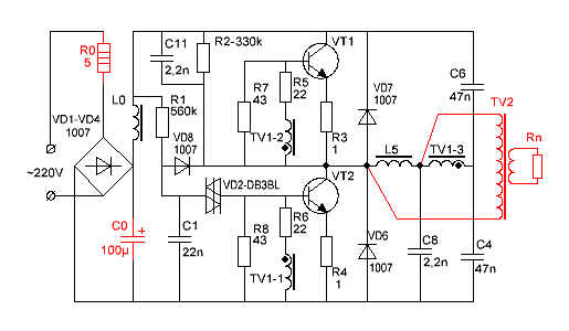
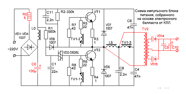
Then, in the area between the former location of the throttle and the reactive midpoint (in the diagram, this segment is located between the isolation capacitors C4 and C6), a new powerful transformer is connected (denoted as TV2). If necessary, an output rectifier is connected to it, consisting of a pair of connecting diodes (they are indicated in the diagram as VD14 and VD15). It does not hurt to replace the diodes on the input rectifier with more powerful ones (in the diagram, this is VD1-VD4).
Do not forget to also install a larger capacitor (shown as C0 in the diagram). You need to select it from the calculation of 1 microfarad per 1 W of output power. In our case, a 100 mF capacitor was taken.
As a result, we get a fully capable switching power supply from energy saving lamp. The assembled circuit will look something like this.
Trial run
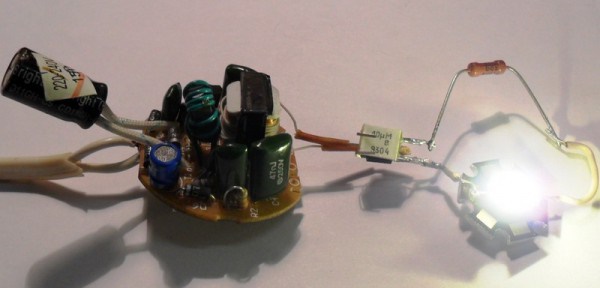
Trial run
Connected to the circuit, it serves as something akin to a stabilizer fuse and protects the unit during current and voltage fluctuations. If everything is good, the lamp does not particularly affect the operation of the board (due to low resistance).
But at jumps of high currents, the resistance of the lamp increases, leveling negative impact on the electronic components of the circuit. And even if the lamp suddenly burns out, it will not be as pitiful as the impulse block assembled by your own hand, over which you pored over for several hours.
The most simple circuit The test chain looks like this.
After starting the system, observe how the temperature of the transformer (or the inductor wound with the secondary) changes. In the event that it starts to get very hot (up to 60ºС), de-energize the circuit and try replacing the winding wires with an analogue with a large cross section, or increase the number of turns. The same applies to the heating temperature of transistors. With its significant growth (up to 80ºС), each of them should be equipped with a special radiator.
That's basically it. Finally, we remind you of the observance of safety rules, since the output voltage is very high. Plus, the components of the board can get very hot without changing their appearance.
We also do not recommend using such impulse blocks when creating chargers for modern gadgets with fine electronics (smartphones, electronic watches, tablets, etc.). Why take such a risk? No one will guarantee that the "home-made" will work stably, and will not ruin an expensive device. Moreover, there are more than enough suitable goods (meaning ready-made chargers) on the market, and they are quite inexpensive.
Such a homemade power supply can be fearlessly used to connect light bulbs. different types, for powering LED strips, simple electrical appliances that are not so sensitive to current (voltage) surges.
We hope you were able to master all the material presented. Perhaps he will inspire you to try to create something similar yourself. Even if the first power supply you make from a light bulb board will not be a real working system at first, you will acquire basic skills. And most importantly - the excitement and thirst for creativity! And there, you see, it will turn out to make a full-fledged power supply for LED strips, which are very popular today, out of improvised materials. Good luck!
"Angel eyes" for a car with your own hands How to make it right homemade lamp from ropes Device and adjustment of dimmable LED strips
In this article you will find detailed description the manufacturing process of switching power supplies of different power based on the electronic ballast of a compact fluorescent lamp.
You can make a switching power supply for 5 ... 20 watts in less than an hour. It will take several hours to manufacture a 100-watt power supply.
Compact Fluorescent Lamps (CFLs) are now widely used. To reduce the size of the ballast choke, they use a high-frequency voltage converter circuit, which can significantly reduce the size of the choke.
If the electronic ballast fails, it can be easily repaired. But, when the bulb itself fails, the light bulb is usually thrown away.

However, the electronic ballast of such a light bulb is an almost ready-made switching power supply (PSU). The only thing in which the electronic ballast circuit differs from a real switching power supply is the absence of an isolation transformer and a rectifier, if necessary.
At the same time, modern radio amateurs are experiencing great difficulty in finding power transformers to power their homemade products. Even if a transformer is found, its rewinding requires the use of a large amount of copper wire, and the weight and size parameters of products assembled on the basis of power transformers are not encouraging. But in the vast majority of cases power transformer can be replaced with a switching power supply. If for these purposes we use ballast from faulty CFLs, then the savings will be a significant amount, especially when it comes to transformers of 100 watts or more.
The difference between the CFL circuit and the pulse power supply
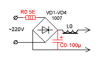
This is one of the most common electrical circuits energy saving lamps. To convert the CFL circuit into a switching power supply, it is enough to install only one jumper between points A - A 'and add a pulse transformer with a rectifier. Items that can be deleted are marked in red.
![]()
And this is already a complete circuit of a switching power supply, assembled on the basis of a CFL using an additional pulse transformer.
To simplify, the fluorescent lamp and a few parts have been removed and replaced with a jumper.
As you can see, the CFL scheme does not require major changes. Marked in red additional elements added to the schema.

What power supply unit can be made from CFL?
The power of the power supply is limited by the overall power of the pulse transformer, maximum admissible current key transistors and the size of the cooling radiator, if used.
A low power power supply can be built by winding the secondary winding directly onto the frame of an existing inductor.
If the choke window does not allow winding the secondary winding, or if it is required to build a power supply with a power significantly exceeding the power of the CFL, then an additional pulse transformer will be needed.
If you want to get a power supply with a power of more than 100 watts, and a ballast from a 20-30 watt lamp is used, then, most likely, you will have to make small changes to the electronic ballast circuit.
In particular, it may be necessary to install more powerful diodes VD1-VD4 in the input bridge rectifier and rewind the input inductor L0 with a thicker wire. If the current gain of the transistors is insufficient, then the base current of the transistors will have to be increased by decreasing the values of the resistors R5, R6. In addition, you will have to increase the power of the resistors in the base and emitter circuits.
If the generation frequency is not very high, then it may be necessary to increase the capacitance of the isolation capacitors C4, C6.
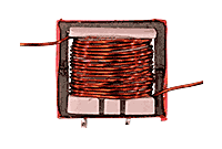
Pulse transformer for power supply

A feature of self-excited half-bridge switching power supplies is the ability to adapt to the parameters of the transformer used. And the fact that the feedback circuit will not pass through our homemade transformer completely simplifies the task of calculating the transformer and setting up the unit. Power supplies assembled according to these schemes forgive errors in calculations up to 150% and more. Proven in practice.
Don't be scared! You can wind a pulse transformer during watching one movie or even faster if you are going to do this monotonous work with concentration.
Input filter capacitance and voltage ripple
In the input filters of electronic ballasts, due to space savings, small capacitors are used, on which the magnitude of the voltage ripple with a frequency of 100 Hz depends.
To reduce the level of voltage ripple at the output of the PSU, you need to increase the capacitance of the input filter capacitor. It is desirable that for every watt of PSU power there is one microfarad or so. An increase in capacitance C0 will entail an increase in the peak current flowing through the rectifier diodes at the moment the PSU is turned on. To limit this current, a resistor R0 is needed. But, the power of the original CFL resistor is small for such currents and should be replaced with a more powerful one.
If you want to build a compact power supply, then you can use electrolytic capacitors used in flash lamps of film "malls". For example, Kodak disposable cameras have unmarked miniature capacitors, but their capacity is as much as 100µF at 350 volts.
A power supply with a power close to the power of the original CFL can be assembled without even winding a separate transformer. If the original inductor has enough free space in the magnetic circuit window, then you can wind a couple of dozen turns of wire and get, for example, a power supply for a charger or a small power amplifier.
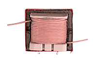
The picture shows that one layer was wound over the existing winding insulated wire. I used MGTF wire ( stranded wire in PTFE insulation). However, in this way it is possible to obtain a power of only a few watts, since most of the window will be occupied by the insulation of the wire, and the cross section of the copper itself will be small.
If more power is required, an ordinary copper lacquered winding wire can be used.
Attention! The original inductor winding is under mains voltage! With the refinement described above, be sure to take care of reliable winding insulation, especially if the secondary winding is wound with ordinary lacquered winding wire. Even primary winding covered with a synthetic protective film, an additional paper pad is required!
As you can see, the winding of the inductor is covered with a synthetic film, although often the winding of these inductors is not protected at all.
We wind two layers of electric cardboard 0.05 mm thick or one layer 0.1 mm thick over the film. If there is no electric cardboard, we use any paper that is suitable in thickness.
We wind the secondary winding of the future transformer over the insulating gasket. The cross section of the wire should be chosen as large as possible. The number of turns is selected experimentally, since there will be few of them.
In this way, I managed to get power at a load of 20 watts at a transformer temperature of 60ºC, and transistors at 42ºC. To get even more power, at a reasonable temperature of the transformer, was not allowed by the too small area of the window of the magnetic circuit and the resulting cross section of the wire.
The power supplied to the load is 20 watts.
The frequency of self-oscillations without load is 26 kHz.
Self-oscillation frequency at maximum load - 32 kHz
Transformer temperature - 60ºС
Transistor temperature - 42ºС
To increase the power of the power supply, I had to wind a TV2 pulse transformer. In addition, I increased the line voltage filter capacitor C0 to 100µF.
Since the efficiency of the power supply is not at all equal to 100%, I had to screw some kind of radiators to the transistors.
After all, if the efficiency of the block is even 90%, you still have to dissipate 10 watts of power.
![]()
I was not lucky, transistors 13003 pos. 1 were installed in my electronic ballast of such a design, which, apparently, is designed to be attached to a radiator using shaped springs. These transistors do not need gaskets, since they are not equipped with a metal pad, but they also give off heat much worse. I replaced them with transistors 13007 pos. 2 with holes so that they can be screwed to the radiators with ordinary screws. In addition, 13007 have several times higher maximum permissible currents.
If you wish, you can safely screw both transistors onto one heatsink. I checked it works.
Only, the cases of both transistors must be insulated from the case of the heatsink, even if the heatsink is inside the case of the electronic device.
Fastening is conveniently carried out with M2.5 screws, on which insulating washers and pieces must first be put on insulating tube(cambric). It is allowed to use heat-conducting paste KPT-8, since it does not conduct current.
Attention! Transistors are under mains voltage, so insulating gaskets must ensure electrical safety conditions!
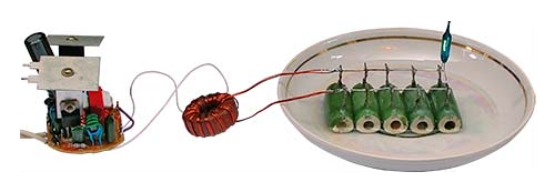
Load dummy resistors are placed in water because their power is insufficient.
The power dissipated at the load is 100 watts.
The frequency of self-oscillations at maximum load is 90 kHz.
The frequency of self-oscillations without load is 28.5 kHz.
The temperature of the transistors is 75ºC.
The heatsink area of each transistor is 27cm².
Throttle temperature TV1 - 45ºC.
TV2 - 2000Nm (Ø28 x Ø16 x 9mm)
Rectifier
All secondary rectifiers of a half-bridge switching power supply must be full-wave. If this condition is not met, then the main line may enter saturation.
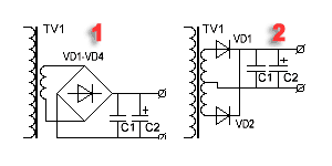
There are two widely used full-wave rectifier circuits.
1. Bridge circuit.
2. Scheme with a zero point.
The bridge circuit saves a meter of wire, but dissipates twice as much energy on the diodes.
The zero point circuit is more economical but requires two perfectly symmetrical secondary windings. Asymmetry in the number of turns or arrangement can lead to saturation of the magnetic circuit.
However, it is the zero-point circuits that are used when it is required to obtain large currents at a low output voltage. Then, for additional minimization of losses, instead of conventional silicon diodes, Schottky diodes are used, on which the voltage drop is two to three times less.
Example.
Rectifiers of computer power supplies are made according to the scheme with a zero point. With a power output of 100 watts and a voltage of 5 volts, even on Schottky diodes, 8 watts can be dissipated.
100 / 5 * 0.4 = 8(Watts)
If you use a bridge rectifier, and even ordinary diodes, then the power dissipated by the diodes can reach 32 watts or even more.
100 / 5 * 0.8 * 2 \u003d 32 (Watts).
Pay attention to this when you design the power supply, so that later you don’t have to look for where half the power has disappeared.

In low-voltage rectifiers, it is better to use a zero-point circuit. Moreover, with manual winding, you can simply wind the winding in two wires. In addition, powerful pulsed diodes are not cheap.
How to properly connect a switching power supply to the network?

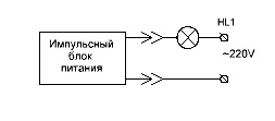
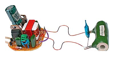
To set up switching power supplies, they usually use just such a switching scheme. Here, the incandescent lamp is used as a ballast with a non-linear characteristic and protects the UPS from failure in abnormal situations. The lamp power is usually chosen close to the power of the tested switching power supply.
When the pulse power supply is idling or at low load, the resistance of the filament of the lamp's kakala is small and it does not affect the operation of the unit. When, for some reason, the current of the key transistors increases, the lamp spiral heats up and its resistance increases, which leads to current limitation to a safe value.

This drawing shows a diagram of a bench for testing and adjusting a pulsed power supply that meets electrical safety standards. The difference between this circuit and the previous one is that it is equipped with an isolation transformer, which provides galvanic isolation of the investigated UPS from the lighting network. The SA2 switch allows you to block the lamp when the power supply delivers more power.
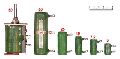
An important operation when testing a PSU is a test on a dummy load. It is convenient to use powerful resistors such as PEV, PPB, PSB, etc. as a load. These "glass-ceramic" resistors are easy to find on the radio market by their green coloring. Red numbers are power dissipation.
From experience it is known that for some reason the power of the equivalent load is always not enough. The resistors listed above can dissipate two to three times the nominal power for a limited time. When the PSU is turned on for a long time to check thermal regime, and the power of the load equivalent is insufficient, then the resistors can simply be lowered into the water.
Be careful, beware of the burn!
Load resistors of this type can reach temperatures of several hundred degrees without any external manifestations!
That is, you will not notice any smoke or color change and you can try to touch the resistor with your fingers.
How to set up a switching power supply?
Actually, the power supply, assembled on the basis of a serviceable electronic ballast, does not require special adjustment.
It must be connected to a load dummy and make sure that the PSU is able to deliver the calculated power.
During the run under maximum load, you need to follow the dynamics of the temperature increase of the transistors and the transformer. If the transformer heats up too much, then you need to either increase the cross section of the wire, or increase the overall power of the magnetic circuit, or both.
If the transistors get very hot, then you need to install them on radiators.
If a homemade choke from a CFL is used as a pulse transformer, and its temperature exceeds 60 ... 65ºС, then the load power must be reduced.
What is the purpose of the circuit elements of a switching power supply?
R0 - limits the peak current flowing through the rectifier diodes at the moment of switching on. In CFL, it also often performs the function of a fuse.
VD1 ... VD4 - bridge rectifier.
L0, C0 - power filter.
R1, C1, VD2, VD8 - converter start circuit.
The launch node works as follows. Capacitor C1 is charged from the source through resistor R1. When the voltage on the capacitor C1 reaches the breakdown voltage of the VD2 dinistor, the dinistor unlocks itself and unlocks the VT2 transistor, causing self-oscillations. After the onset of generation, rectangular pulses are applied to the cathode of the VD8 diode and the negative potential securely locks the VD2 dinistor.
R2, C11, C8 - make it easier to start the converter.
R7, R8 - improve the locking of transistors.
R5, R6 - limit the current of the bases of transistors.
R3, R4 - prevent saturation of transistors and act as fuses during breakdown of transistors.
VD7, VD6 - protect transistors from reverse voltage.
TV1 - feedback transformer.
L5 - ballast choke.
C4, C6 - separating capacitors, on which the supply voltage is divided in half.
TV2 - pulse transformer.
VD14, VD15 - pulse diodes.
C9, C10 - filter capacitors.
While scientists are taming the speed of light, I've decided to tame unnecessary fluorescent lamps by converting them into LEDs. Compact fluorescent lamps (CFLs) are a bit of a thing of the past, for obvious reasons: lower efficiency compared to LEDs, environmental insecurity (mercury), ultraviolet radiation dangerous to human eyes, and fragility.
Like many radio amateurs, a whole box of this "good" has accumulated. Less powerful ones can be used as spare parts, but those that are more powerful, starting from 20W, power sources can also be redone. After all, an electronic ballast is a cheap voltage converter, that is, a simple and affordable switching power supply that can power devices up to 30-40W (depending on the CFL), and even more if you change the output choke and transistors. Those radio amateurs who live in remote places, or in certain situations, these "energy savers" will be useful. So, do not rush to throw them away after failure - and they do not work for long!

In my case, about a year ago (in the spring of 2014), having started experimenting with electronic ballast, in search of a body for alteration in led lamp, returning home from work in the evening, it dawned on me - I saw a can of cola on the sidewalk. After all, an aluminum case from under 0.25L of a drink is just right as a radiator for dissipating heat from an LED strip. And also, it fits perfectly under the body of the Vitoone CFL with an E27 base, at 25 W. Yes, and not bad in aesthetics!

Having made several converted LED lamps, I began to test them in different conditions operation. One of them works in the utility room in the heat and frost (with ventilation holes), the other in the living room (without a hole in the plastic base). Another one is connected to a three-meter led strip. It's been almost a year and they still work flawlessly! Well, and given that more and more articles appear on the topic of LEDs, I finally had to write about my time-tested idea.
Discuss the article UNIVERSAL LED LAMP
The power supply is a useful and very important device in amateur radio practice. Now you can buy a power supply of any power (within reason), size and price, but sometimes they are significantly inferior to homemade power supplies. In this article, we will consider the option of making a home-made power supply from electronic ballast (ballast for an energy-saving lamp).
There are many designs with the use of electronic ballasts. The design of such a block is quite simple, the price does not exceed 2-2.5 US dollars. This is a switching power supply designed to increase mains 220 volts to a higher rating, which feeds energy saving light bulb. The ballast circuit is quite simple, it is a boost converter (most often a push-pull).

Imported transistors MJE13003, MJE13007, in rare cases MJE13009 and their analogues are used as power switches. Transistors can be said to have been created specifically to work in network UPSs. Similar transistors are also used in computer power supplies. So, for starters, I want to introduce the main advantages of such a power supply.
- Compact size and light weight
- Low costs and low cost
- Reliability
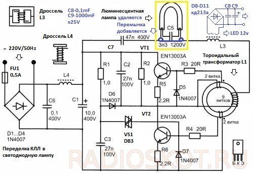
Schemes, device and operation of energy-saving lamps
Compact energy-saving lamps work in the same way as conventional fluorescent lamps with the same conversion principle. electrical energy into the light. The tube has two electrodes at the ends, which heat up to 900-1000 degrees and emit many electrons, accelerated by the applied voltage, which collide with argon and mercury atoms. The emerging low-temperature plasma in mercury vapor is converted into ultraviolet radiation. The inner surface of the tube is coated with a phosphor that converts ultraviolet radiation into visible light. Connected to the electrodes AC voltage, so their function is constantly changing: they become the anode, then the cathode. The voltage generator supplied to the electrodes operates at a frequency of tens of kilohertz, so energy-saving lamps, compared to conventional ones, fluorescent lamps, do not flicker.
Let's analyze the operation of an energy-saving lamp using the example of the most common circuit (11W lamp).
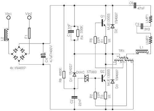
The circuit consists of power circuits, which include an anti-interference inductor L2, fuse F1, diode bridge, consisting of four 1N4007 diodes and a filter capacitor C4. The start circuit consists of elements D1, C2, R6 and a dinistor. D2, D3, R1 and R3 perform protective functions. Sometimes these diodes are not installed in order to save money.
When the lamp is turned on, R6, C2 and the dinistor form a pulse that is applied to the base of the transistor Q2, leading to its opening. After starting, this part of the circuit is blocked by diode D1. After each opening of the transistor Q2, the capacitor C2 is discharged. This prevents the dinistor from reopening. The transistors excite the transformer TR1, which consists of a ferrite ring with three windings in several turns. The filament is energized through capacitor C3 from the boost resonant circuit L1, TR1, C3 and C6. The tube lights up at the resonant frequency determined by capacitor C3 because its capacitance is much smaller than that of C6. At this point, the voltage across the capacitor C3 reaches about 600V. During start-up, peak currents are 3-5 times normal, so if the lamp bulb is damaged, there is a risk of damaging the transistors.
When the gas in the tube is ionized, C3 is practically shunted, whereby the frequency is lowered and the oscillator is controlled only by capacitor C6 and generates less voltage, but still enough to keep the lamp lit.
When the lamp is lit, the first transistor turns on, which saturates the TR1 core. Feedback to the base causes the transistor to turn off. Then the second transistor opens, excited by the oppositely connected winding TR1, and the process is repeated.
Energy-saving lamp failures
Capacitor C3 often fails. Typically, this happens in lamps that use cheap components designed for low voltage. When the lamp stops lighting, there is a risk of failure of transistors Q1 and Q2 and, as a result, R1, R2, R3 and R5. When starting the lamp, the generator is often overloaded and the transistors often cannot withstand overheating. If the lamp bulb fails, the electronics usually break too. If the bulb is already old, one of the coils may burn out and the lamp will stop working. Electronics in such cases, as a rule, remains intact.
Sometimes the lamp bulb can be damaged due to deformation, overheating, temperature difference. Most often, the lamps burn out at the moment of switching on.
Repair
Repair usually consists of replacing the broken capacitor C3. If the fuse blows (sometimes it is in the form of a resistor), transistors Q1, Q2 and resistors R1, R2, R3, R5 are probably faulty. Instead of a blown fuse, you can install a resistor of several ohms. There may be several faults at once. For example, when a capacitor breaks down, transistors can overheat and burn out. As a rule, transistors MJE13003 are used.
In order to make the lamp mode softer, the energy-saving lamp can be
We advise you to read
 Psychological characteristics of children in adolescence
 Transferring a child to another school - the procedure and necessary documents Whether to transfer a child to another school
, diagnosis, treatment Treatment of urogenital chlamydia") Chlamydia urogenital - description, causes, symptoms (signs), diagnosis, treatment Treatment of urogenital chlamydia
Chlamydia urogenital - description, causes, symptoms (signs), diagnosis, treatment Treatment of urogenital chlamydia The benefits and significance of hydroamino acid threonine for the human body L threonine what

