The so-called lamps daylight” (LDS) are certainly more economical than conventional incandescent lamps, and they are much more durable. But, unfortunately, they have the same "Achilles heel" - filaments. It is the heating coils that most often fail during operation - they simply burn out. And the lamp has to be thrown away, inevitably polluting environment harmful mercury. But not everyone knows that such lamps are still quite suitable for further work.
In order for the LDS, in which only one filament has burned out, to continue to work, it is enough just to bridge those pin terminals of the lamp that are connected to the burned out filament. It is easy to identify which thread is burned out and which is intact with an ordinary ohmmeter or tester: a burnt thread will show an infinitely high resistance on the ohmmeter, but if the thread is intact, the resistance will be close to zero. In order not to mess with soldering, several layers of foil (from a tea wrapper, milk bag or cigarette packaging) paper are strung on the pins coming from the burnt out thread, and then the entire “layer cake” is carefully cut with scissors along the diameter of the lamp base. Then the LDS connection scheme will turn out as shown in Fig. 1. Here, the fluorescent lamp EL 1 has only one (left according to the diagram) whole thread, the second (right) is short-circuited by our impromptu jumper. Other elements of the fittings of a fluorescent lamp - such as the L1 choke, neon (with bimetallic contacts) starter EK1, as well as the noise suppression capacitor C3 (with a rated voltage of at least 400 V), may remain the same. True, the LDS ignition time with such a modified scheme can increase to 2 ... 3 seconds.
The lamp works in such a situation like this. As soon as a 220 V mains voltage is applied to it, the EK1 starter neon lamp lights up, causing its bimetallic contacts to heat up, as a result of which they eventually close the circuit, connecting the L1 choke - through a whole filament to the network. Now this remaining thread heats up the mercury vapor in the LDS glass flask. But soon the bimetallic contacts of the lamp cool down (due to the extinction of the neon) so much that they open. Due to this, a high-voltage pulse is formed on the inductor (due to the self-induction EMF of this inductor). It is he who is able to “set fire” to the lamp, in other words, to ionize mercury vapor. The ionized gas just causes the glow of the powder phosphor, with which the bulb is coated from the inside along the entire length.
But what if both filaments burned out in the LDS? Of course, it is permissible to bridge the second thread. However, the ionization ability of a lamp without forced heating is significantly lower, and therefore a high-voltage pulse here will require a larger amplitude (up to 1000 V or more).
To reduce the "ignition" voltage of the plasma, auxiliary electrodes can be arranged outside the glass bulb, as if in addition to the two existing ones. They can be an annular belt glued to the flask with BF-2, K-88, Moment glue, etc. A belt about 50 mm wide is cut out of copper foil. A thin wire is soldered to it with POS solder, electrically connected to the electrode of the opposite end of the LDS tube. Naturally, the conductive belt is covered from above with several layers of PVC iso-tape, "adhesive tape" or medical adhesive tape. The scheme of such refinement is shown in fig. 2. It is interesting that here (as in the usual case, that is, with whole filaments), it is not at all necessary to use a starter. So, the closing (normally open) button SB1 is used to turn on the lamp EL1, and the opening (normally closed) button SB2 is used to turn off the LDS. Both of them can be of the type KZ, KPZ, KN, miniature MPK1-1 or KM1-1, etc. P.
In order not to bother winding the conductive belts, which do not look very nice outwardly, assemble a voltage quadruple (Fig. 3). It will allow you to forget once and for all about the problem of burning out unreliable filaments.
Quadruple contains two conventional rectifiers with voltage doubling. So, for example, the first of them is assembled on capacitors C1, C4 and diodes VD1, VD3. Due to the action of this rectifier on the capacitor C3 is formed constant pressure about 560V (since 2.55 220V = 560V). A voltage of the same magnitude arises on capacitor C4, therefore, a voltage of the order of 1120 V appears on both capacitors C3, C4, which is quite sufficient to ionize mercury vapor inside the LDS EL1. But as soon as ionization has begun, the voltage on the capacitors C3, C4 decreases from 1120 to 100 ... 120 V, and on the current-limiting resistor R1 drops to about 25 ... 27 V.
It is important that paper (or even electrolytic oxide) capacitors C1 and C2 must be rated for a nominal (working) voltage of at least 400 V, and mica capacitors C3 and C4 - 750 V or more. The powerful current-limiting resistor R1 is best replaced with a 127-volt incandescent bulb. The resistance of the resistor R1, its dissipation power, as well as suitable 127-volt lamps (they should be connected in parallel) are indicated in the table. It also provides data on the recommended diodes VD1-VD4 and the capacitance of capacitors C1-C4 for LDS of the required power.
If a 127-volt lamp is used instead of a very hot resistor R1, its filament will barely glow - the heating temperature of the filament (at a voltage of 26 V) does not even reach 300 ° C (dark brown color of heat, indistinguishable to the eye even in complete darkness) . Because of this, 127-volt lamps here can last almost forever. They can be damaged only purely mechanically, for example, by accidentally breaking a glass flask or “shaking off” a thin hair of a spiral. 220-volt lamps would heat up even less, but their power would have to be taken excessively large. The fact is that it should exceed the power of the LDS by about 8 times!
Which LDS “resuscitation” scheme to apply, choose for yourself, based on your taste and capabilities.
Magazine "CAM" №10, 1998
All right with electricity with mosquitoes too.
220V 1kW
The device is designed to supply household consumers with alternating current. Rated voltage 220 V, power consumption 1 kW. The use of other elements allows the device to be used to power more powerful consumers.
The device, assembled according to the proposed scheme, is simply inserted into the socket and the load is powered from it. All electrical wiring remains intact. Grounding is not required. The meter takes into account about a quarter of the consumed electricity.
Theoretical basis:
The operation of the device is based on the fact that the load is not powered directly from the network alternating current, but from a capacitor, the charge of which corresponds to the sinusoid of the mains voltage, but the charging process itself occurs in pulses high frequency. The current consumed by the device from the electrical network is a high-frequency pulse. Electricity meters, including electronic ones, contain an input induction converter, which has low sensitivity to high frequency currents. Therefore, energy consumption in the form of pulses is taken into account by the meter with a large negative error.
circuit diagram devices:
The main elements are the power rectifier Br1, the capacitor C1 and the transistor switch T1. Capacitor C1 is connected in series to the power supply circuit of the rectifier Br1, therefore, at times when Br1 is loaded on the open transistor T1, it is charged to the instantaneous value of the mains voltage corresponding to this moment in time.
The charge is produced by pulses with a frequency of 2 kHz. The voltage on C1, as well as on the load connected in parallel to it, is close to sinusoidal in shape with an effective value of 220 V. To limit the pulsed current through the transistor T1 during the charging of the capacitor, a resistor R6 is connected in series with the key stage
On the logical elements DD1, DD2 assembled master oscillator. It generates pulses with a frequency of 2 kHz with an amplitude of 5V. The frequency of the signal at the output of the generator and the duty cycle of the pulses are determined by the parameters of the timing circuits C2-R7 and C3-R8. These parameters can be selected during setup to ensure the greatest error in electricity metering. A pulse shaper is built on transistors T2 and T3, designed to control a powerful key transistor T1. The shaper is designed in such a way that T1 in the open state enters saturation mode and due to this, less power is dissipated on it. Naturally, T1 must also be completely closed.
Transformer Tr1, rectifier Br2 and the elements following them are the power source of the low-voltage part of the circuit. This source supplies 36V to the pulse shaper and 5V to power the oscillator chip.
Device details:
Chip: DD1, DD2 - K155LA3. Diodes: Br1 - D232A; Br2 - D242B; D1 - D226B. Zener diode: D2 - KS156A. Transistors: T1 - KT848A, T2 - KT815V, T3 - KT315. T1 and T2 are installed on a radiator with an area of at least 150 cm2. The transistors are mounted on insulating pads. Electrolytic capacitors: C1- 10 uF Ch 400V; C4 - 1000 uF H 50V; C5 - 1000 uF H 16V; High-frequency capacitors: C2, C3 - 0.1 uF. Resistors: R1, R2 - 27 kOhm; R3 - 56 Ohm; R4 - 3 kOhm; R5 -22 kOhm; R6 - 10 Ohm; R7, R8 - 1.5 kOhm; R9 - 560 Ohm. Resistors R3, R6 - wire with a power of at least 10 W, R9 - type MLT-2, the rest of the resistors - MLT-0.25. Transformer Tr1 - any low-power 220/36 V.
Adjustment:
Be careful when setting up the circuit! Remember that the low-voltage part of the circuit is not galvanically isolated from the mains! It is not recommended to use the metal case of the device as a radiator for transistors. The use of fuses is a must!
First, the low-voltage power supply is checked separately from the circuit. It must provide at least 2A of 36V output, as well as 5V to power a low power generator.
Then the generator is adjusted by disconnecting the power part of the circuit from the mains. The generator should generate pulses with an amplitude of 5 V and a frequency of about 2 kHz. The duty cycle of the pulses is approximately 1/1. If necessary, capacitors C2, C3 or resistors R7, R8 are selected for this.
The pulse shaper on transistors T2 and T3, if properly assembled, usually does not require adjustment. But it is desirable to make sure that it is able to provide a pulse current of the base of the transistor T1 at a level of 1.5 - 2 A. If this current value is not provided, the transistor T1 will not enter saturation mode in the open state and will burn out in a few seconds. To check this mode, with the power section of the circuit turned off and the base of the transistor T1 turned off, instead of the resistor R1, turn on a shunt with a resistance of several ohms. impulse voltage on the shunt with the generator turned on, they are recorded by an oscilloscope and recalculated to the current value. If necessary, select the resistance of resistors R2, R3 and R4.
The next step is to check the power section. To do this, restore all connections in the circuit. Capacitor C1 is temporarily disconnected, and a low power consumer is used as a load, for example, an incandescent lamp with a power of up to 100 W. When the device is turned on electrical network the effective value of the voltage at the load should be at the level of 100 - 130 V. Oscillograms of the voltage at the load and at the resistor R6 should show that it is powered by pulses with a frequency set by the generator. On the load, a series of pulses will be modulated by a sinusoid of the mains voltage, and on the resistor R6 - by a pulsating rectified voltage.
If everything is in order, the capacitor C1 is connected, only at the beginning its capacitance is taken several times less than the nominal one (for example, 0.1 μF). The operating voltage at the load increases markedly and, with a subsequent increase in capacitance C1, reaches 220 V. In this case, it is very important to carefully monitor the temperature of the transistor T1. If excessive heat occurs when using low power load, this indicates that T1 either does not enter saturation mode in the open state, or does not close completely. In this case, you should return to the setting of the pulse shaper. Experiments show that when a load with a power of 100 W is supplied without capacitor C1, transistor T1 does not heat up for a long time even without a radiator.
In conclusion, the nominal load is connected and the capacitance C1 is selected so as to provide the load with a voltage of 220 V. The capacitance C1 should be selected carefully, starting from small values, since an increase in capacitance sharply increases the pulse current through the transistor T1. The amplitude of the current pulses through T1 can be judged by connecting the oscilloscope in parallel with the resistor R6. Pulse current should be no more than allowed for the selected transistor (20 A for KT848A). If necessary, it is limited by increasing the resistance R6, but it is better to stop at a lower value of capacitance C1.
With the specified details, the device is designed for a load of 1 kW. Using other elements of the power rectifier and a transistor switch of the appropriate power, it is possible to power more powerful consumers. Please note that when the load is off, the device consumes quite a lot of power from the network, which is taken into account by the meter. Therefore, it is recommended to always load the device with a rated load, and also turn it off when the load is removed.
Spring came...
Mosquitoes?
Spring has come, and with it new problem- mosquitoes and midges, which sometimes just drive you crazy. But for people whose hands grow from the right place, this is not a problem! We know how to find a way out of any difficult situation! And this time we will assemble a mosquito repeller! As you know, mosquitoes really do not like ultrasound, and we will use this:
Here is a simple transistor circuit:
Another circuit on transistors, but more complicated:
And here is a very simple one on a microcircuit:
Burnt out LDS?
LDS with two burned out threads.
In order not to bother winding conductive belts, which do not look very pretty, assemble a voltage quadruple. It will allow you to forget about the problem of burning out unreliable filaments once and for all.
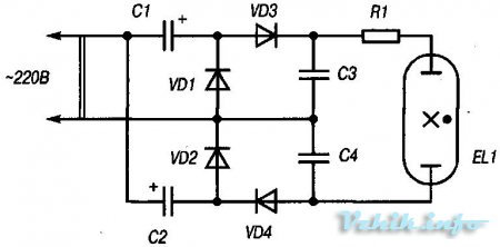
A simple circuit for switching on an LDS with two burnt filaments using a voltage quadrupler
Quadruple contains two conventional rectifiers with voltage doubling. Due to the action of this rectifier, a constant voltage of about 560V is formed on the capacitor C3 (since 2.55 * 220 V = 560 V). A voltage of the same magnitude arises on capacitor C4, therefore, a voltage of the order of 1120 V appears on both capacitors C3, C4, which is quite sufficient to ionize mercury vapor inside the LDS EL1. But as soon as ionization has begun, the voltage on the capacitors C3, C4 decreases from 1120 to 100 ... 120 V, and on the current-limiting resistor R1 drops to about 25 ... 27 V.
It is important that paper (or even electrolytic oxide) capacitors C1 and C2 must be rated for a nominal (working) voltage of at least 400 V, and mica capacitors C3 and C4 - 750 V or more. The powerful current-limiting resistor R1 is best replaced with a 127-volt incandescent bulb. The resistance of the resistor R1, its dissipation power, as well as suitable 127-volt lamps (they should be connected in parallel) are indicated in the table. It also provides data on the recommended diodes VD1-VD4 and the capacitance of capacitors C1-C4 for LDS of the required power.
If, instead of a very hot resistor R1, a 127-volt lamp is used, its filament will barely glow - the heating temperature of the filament (at a voltage of 26 V) does not even reach 300ºС (dark brown color of heat, indistinguishable to the eye even in complete darkness). Because of this, 127-volt lamps here can last almost forever. They can be damaged only purely mechanically, for example, by accidentally breaking a glass flask or “shaking off” a thin hair of a spiral. 220-volt lamps would heat up even less, but their power would have to be taken excessively large. The fact is that it should exceed the power of the LDS by about 8 times!
Parameters of parts used in the voltage quadruple circuit
For a long time I could not find a vitrified wire resistance with a power of 40 W and a nominal value of 60 Ohms. I had to connect in parallel 5 ... 6 suitable resistors. But when testing the circuit, these resistors got very hot, and this is unsafe in terms of fire. And an idea came to me: whether to use the heat energy dissipated by resistors, converting it into another, light energy. And it worked. The thing is that I used a conventional 220-volt electric incandescent lamp with a power of 25 W as a resistor, turning it on in series with an LB-40 fluorescent lamp through a D226 B diode (it is possible without a diode). Thus, I not only restored the work of a burned-out fluorescent lamp, but also forced an ordinary lamp to give light.
Such a device with two light sources is convenient to use in separated bathroom and toilet, basement and garage and other places. Both sources light up instantly, and the glow of the fluorescent lamp is not accompanied by annoying buzzing and flashing, which are observed in circuits with a control gear choke (ballast) and a starter. Of course, you will have to buy an incandescent lamp, but the cost of it will soon pay off (it lasts a very long time in this circuit, and it burns without blinking, which would happen when the lamp was connected to the network through a diode. In this case, the lamp burns with full heat.
In the scheme of the modified device shown in Fig., the following radio components are used. Diodes VD2 and VD3 (type D226 B) and capacitors C1 and C4 (type K61-K, capacitance 6 μF, operating voltage 600 V) represent a full-wave rectifier. The values of capacitances C1 and C4 determine the operating voltage of the fluorescent lamp (the larger the capacitance of the capacitors, the greater the voltage on the lamp electrodes). When the circuit is idling (without an HL1 or HL2 lamp), the voltage at points a and b reaches 1200 V. Therefore, be careful.
Scheme for switching on a burnt out fluorescent lamp
Capacitors C2 and C3 (type KBG-M2; capacitance 0.1 μF; operating voltage 600V) help suppress radio interference and, together with diodes VD1 and VD4 and capacitors C1 and C4, create a voltage of 420 V at points a and b, ensuring reliable ignition of the lamp in moment of inclusion. It is necessary to pay attention to the polarity of the connection of the fluorescent lamp. So, if the lamp does not light up, turn the tube 180 ° and reinsert it into the cartridges. The terminals in the cartridges or on the tube itself are short-circuited for ignition reliability. But some tubes (in which, apparently, the spirals have completely crumbled) do not ignite. Good tubes connected to the circuit burn better and brighter.
When replacing an incandescent lamp with a more powerful one, the latter burns dimmer, but the glow of the tube remains constant.
The circuit can work without diodes VD1 and VD4 and capacitors C2 and C3, but the switching reliability decreases.
Fluorescent lights are much more economical and last longer than incandescent lights. But the scheme of their connection to the 220V network is more complicated and requires additional elements: throttle and starter. In addition, the disadvantage of the most common circuit is the way the lamp is ignited, when current is passed through its filaments (to warm them up) to the starter; in this case, current surges often disable the filaments (they burn out), and the lamp does not light up, although it itself remains operational. Hairs (filaments) can also break from careless handling of the lamp, such as shaking it. Innovators have long come up with many schemes for starting a lamp without a starter, when its filaments are not heated and, therefore, their breakage does not affect the operation of the lamp. One of these schemes, the simplest in execution, is offered to readers.
In this circuit, the lamp is ignited by supplying 600-620 V to its electrodes (filaments), obtained using capacitors and diodes connected according to the voltage doubling circuit. After the lamp is ignited, the voltage on it (due to the discharge of capacitors through the lamp and the drop on the throttle) drops to the normal 95-100 V, and the lamp burns steadily. In this case, the voltage doubling no longer occurs, and the lamp is powered by a rectified mains voltage. For a rectifier bridge, you need to take diodes designed for a reverse voltage of at least 400V and a current of at least 300 tA, the widely used D226B, D229B, D205 or KC-
401 B, KTs-401 G. This is for lamps up to 40 W, for lamps of higher power, more powerful diodes KD202L, KD205B or rectifier bridges KTs-402V, KTs-405V are also needed. Capacitors are also selected for an operating voltage of at least 300V, it is best to use non-polar ones, such as BGT, KBG, OKBG, K42-4 and others with a capacity of 0.25-1.6 microfarads, both should be the same. For each lamp, you need a choke corresponding to its power. There are circuits where wire resistances (resistors) or incandescent lamps (100 W, for a fluorescent lamp - 40 W) are used instead of a choke, but their use is limited due to high heating.
Lamp Wiring Diagram
The proposed scheme has been tested in practice, its only drawback is the gradual darkening from one end of the cylinder, which appears some time after the start of operation. After darkening 6-10 cm from the end of the balloon, the lamp can be rearranged with the ends.
AT standard scheme A lamp with a fluorescent lamp uses three parts: the lamp itself, the throttle and the starter. The latter is used only to start the lamp, then it does not take any part in the operation of the lamp. In the figure below, from the first diagram, it can be seen that you can do without a starter, but in this case, the lamp will have to be started with a special button through the capacitor.
In the second diagram (on the right), the starter is replaced by four parts; with this scheme, even burnt out lamps can be started.
Both schemes have been tested and have been working at home for more than a year.
Interest in the search for original technical solutions that make it possible to light even burnt out fluorescent lamps does not weaken at the present time. And this sometimes gives truly amazing results.
ways restore fluorescent lamp a lot has been described on the Internet and in the literature ( and we are no exception - see the material Eternal fluorescent lamp), but in almost all these cases revive fluorescent lamp only possible when both threads of the channel are healthy.
Here we present a couple of options. how can you revive a fluorescent lamp if one of the filaments is broken.
When repeating these schemes, it must be borne in mind that the LDS filament, which remains "live", operates with overload, since the burnt filament is shunted by a "wire jumper". Such a forced lamp operation mode due to a halving of the resistance of the filament circuit leads to its rapid wear, and it fails.In addition, the "resuscitation" scheme given in requires an additional installation of a start button, so when controlling the LDS using a wall switch, a problem arises - where to place this start button to turn on the lamp installed on the ceiling?
In the “resuscitation” circuit, which is shown in Fig. 1, there are no such shortcomings. As can be seen from Fig. 1, the burned-out filament of the LDS is shunted not by a jumper, but by a wire resistor, the resistance of which is equal to the cold resistance of the filament. For lamps with a power of 20 and 30 W (LBK22, LBUZO) this resistance is 2 ... 3 Ohm. The wire resistor R1 is made on a resistor of the type BC-0.25 10 kOhm and consists of 2-3 turns of nichrome wire with a diameter of 0.15 ... 0.2 mm .
As a resistor R1, it is very convenient to use a variable wire resistor of the type SP5-28A with a nominal value of 33 ohms or the like, choosing the value of its resistance during setup so that the LDS filament does not overload (at start-up it should be red or pink when the lamp is ignited with confidence) . When setting up the circuit, it is also necessary to take into account the recommendations that ensure reliable ignition of the LDS.
In order to bring the operation of the LDS closer during its start-up to work with whole filaments, three parallel-connected incandescent bulbs of the MN 13.5-0.18 type (with a voltage of 13.5 V and a current of 0, 18 A). Their current-voltage characteristic (CVC) is the same as the CVC of the LDS incandescent filament. Instead of these three bulbs, you can use one car lamp 12 V x 6 St.
However, during "resuscitation" there may be cases when it is not possible to achieve normal operation of the LDS using the circuit in Fig. 1. The lamp lights up heavily and blinks at a frequency of 25 Hz, despite all the tricks indicated in. This blinking is not eliminated even when the SF1 starter is removed and is accompanied by increased heating of the inductor.This operation of the lamp is explained by the fact that it switched to a single-wave mode of operation due to the loss of emission by one of the electrodes, i.e. the lamp works like a diode, passing current in only one direction, as a result, a constant flows through the inductor component of the rectified current, which causes it to heat up.
In this case, provide normal work LDS directly from the AC mains fails. But revive the lamp it is possible in this case too, it can still work reliably if it is switched to a single-direction current supply by connecting it to the output of a half-wave rectifier. Figure 2 shows such a switching circuit. The operation of the lamp according to this circuit is similar to the operation of the lamp in Fig. 1, except that a unidirectional current flows through it with a frequency of 100 Hz, while the whole filament acts as the cathode of the lamp, and the damaged one acts as the anode.
As bridge diodes VD1 ... VD4, you can use assemblies of types KTs402 ... KTs405 for 600 V and a current of 1 A for LDS with a power of 20, 30, 40 and 65 W. Very convenient assembly type KTs404, which has a fuse holder.
Literature
1. Khovaiko V. Recovery fluorescent lamps//Radio. - 1997.
- №7 -С.37
2. Eserkenov K. The method of “resuscitation” of fluorescent lamps//Radio.
- 1998. - No. 2. - C.61.
We advise you to read
 Psychological characteristics of children in adolescence
 Transferring a child to another school - the procedure and necessary documents Whether to transfer a child to another school
, diagnosis, treatment Treatment of urogenital chlamydia") Chlamydia urogenital - description, causes, symptoms (signs), diagnosis, treatment Treatment of urogenital chlamydia
Chlamydia urogenital - description, causes, symptoms (signs), diagnosis, treatment Treatment of urogenital chlamydia The benefits and significance of hydroamino acid threonine for the human body L threonine what

