Power supply systems in Russian residential buildings use 220 V single-phase AC throughout, while the use of some types of electrical equipment requires a 380 V power source. This equipment includes most wood and metalworking machines used on the farm for processing small parts .
Obtaining a 380 V Power Supply Using a Converter
To connect to home network power supply of consumers designed to operate from three-phase network 380 V, use special converters, also known as inverters. In addition to the main function, the converter allows you to adjust the frequency of the motor in a wide range, which can significantly reduce energy consumption compared to equipment operating at a constant frequency. The principle of operation of the inverter is based on double current frequency conversion and the formation of a three-phase linear voltage system of 220 V at the output.
The design of the converter must provide for the presence of a protection system that excludes the possibility of an overload on short circuit and current strength, as well as protection against overheating. Modern models of converters provide a smooth start of the engine, in which the increase in the starting voltage occurs at constant value its relation to the phase current.
The mass and overall dimensions of the inverters make it easy to carry them around. The main disadvantage of using a converter is the rather high cost of the device, so buying it with infrequent use of three-phase equipment may be impractical.
Alternative connection methods
Another way to obtain a 380 V voltage source is to use 3 phases from 220 V power supplies. In an urban apartment building, this method requires prior approval from the organization responsible for energy supervision.
If it is possible to connect the equipment to a three-phase switchboard, voltage conversion may not be required. AT apartment buildings switchboard for each
Converter 220V >>> 380V
Currently, many design enthusiasts, owners of personal subsidiary farms are interested in the use of three-phase asynchronous motors in a single-phase network. Asynchronous motors are structurally very simple and unpretentious in operation, which ensures their greatest distribution among consumers. However, the operation of three-phase motors in a single-phase network is associated with a number of difficulties. As is known from the course of electrical engineering, a three-phase variable electricity generates a rotating magnetic field, which creates a torque on the motor shaft. A single-phase current creates a pulsating field that is not capable of causing the motor rotor to rotate - such a current must be converted into a multi-phase one and only then fed to the electric motor. At present, there are many ways to convert single-phase current into multiphase, but all of them, as a rule, have a number of disadvantages:
It is difficult to obtain a "clean" three-phase current (to achieve a phase difference of 120° between phases). In most cases, a two-phase current is obtained with a phase difference Δφ=90°. Operation at this current leads to a significant loss of motor power. Theoretically, such losses amount to 30-40%, in reality - much more (50-60%). For example, from a three-phase electric motor with a power of 2 kW, 800 W can remain in a single-phase network;
Single-phase current converters are not universal. They are created for a specific electric motor, have power limitations, etc. At the same time, there are certain types of three-phase electric motors that cannot be started in a single-phase network by all known methods.
The presence of reactive elements (usually capacitors) for starting and operating an electric motor creates a number of operational inconveniences, makes the design cumbersome and not always safe in everyday life, etc.
The proposed universal converter of single-phase current to three-phase, built on the basis of a conventional three-phase electric motor, is completely devoid of these shortcomings:
Able to produce a "full" three-phase current, incl. voltage 380 V;
No loss in engine power;
Suitable for any type of electric motors and any power (power is limited by the power grid within 7 kW);
Structurally very simple. A person who is proficient in electrical engineering high school, will make it within 1-2 hours. Its construction requires a three-phase asynchronous motor With squirrel-cage rotor power of 3-4 kW, one capacitor with a capacity of 40-60 microfarads and a set of mounting wire. A three-phase motor does not require any alteration.
Own energy consumption is minimal. The converter of the author of this article with a power of 4 kW consumes approximately 200 watts at idle.
Consider the basic principles underlying the operation of the converter. To do this, remember the device and work synchronous generator three-phase current. It consists of a rotor and a stator. Three stator windings are shifted in space by an angle of 120°. With the help of an external energy source, the generator rotor is driven into rotation, and its changing magnetic flux induces induction EMF in the stator windings. If the stator windings are connected to the consumer, a three-phase electric current will appear in the circuit. To obtain a single-phase current, conclusions from one stator winding are used. three-phase generator. Such a current is most often used for domestic needs and personal consumption.
Now let's try, having one phase, to restore the remaining two. Let's take a conventional three-phase asynchronous electric motor with a squirrel-cage rotor. It also has a rotor and three stator windings shifted in space by an angle of 120°. Let's apply a single-phase current to one of the windings. For the above reasons, the rotor of such an engine will not be able to start rotating itself. But, if by an extraneous force, to inform him of the initial rotating moment, then he will continue to rotate due to the alternating single-phase voltage in one winding. (Strict scientific explanation I omit this fact, because it is widely known from the course of electrical engineering). The rotating rotor with its magnetic flux will induce the induction EMF in the other two stator windings, i.e. restore the missing two phases. Thus, we get something like a rotating three-phase transformer. One of the motor windings, which is supplied with a single-phase alternating current from the network, becomes an exciting winding that forms the magnetic field of a rotating rotor, and it, in turn, excites AC voltage in the remaining windings.
The resulting voltage will be three-phase, because. this is due to the design of the electric motor itself. The voltage on the two remaining windings will be slightly less than the voltage on the exciting winding (due to conversion losses). This difference is approximately 10-15 V and is determined design features electric motor.
Fig.1 Block diagram of the universal converter.
How to make the converter rotor rotate from a single-phase voltage? There are several such methods. I recommend using the widely used start capacitor circuit.
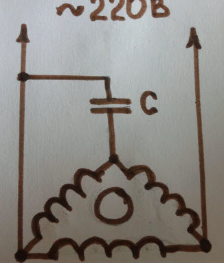
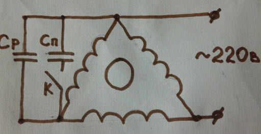
Fig.2 Scheme of a universal converter.
The task is only to bring the neutral wire from the star.
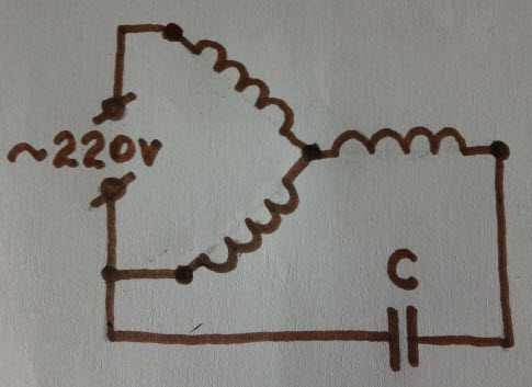
Fig.3 Scheme of a universal converter.
The capacitance of the capacitor Sp can be small, because. the rotor of the asynchronous converter is driven without mechanical load on the shaft. For a converter built on the basis asynchronous motor with a power of 4 kW (author's version), a capacitor Sp \u003d 60 μF is enough. Experiments carried out with such a converter gave good results, but at the same time, some shortcomings were identified:
The voltage of 380 V is very dangerous for human life. To reduce the likelihood of an emergency, in everyday life, it is advisable to use line voltage 220V;
The converter's own power consumption was significant. This reduced the efficiency of the device, especially in the "idle" mode.
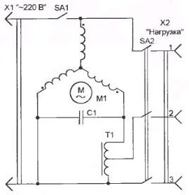
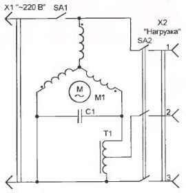
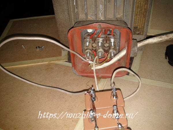
Further modernization of the design made it possible to get rid of these shortcomings. So, an asynchronous 4-kilowatt electric motor with a 6-pole stator winding (the so-called "thousander") was used as a converter. Its windings are turned on by a "star" and are designed for a linear voltage of 380 V. I connected them to 220 V (t i.e. between the "phase" and "zero" of the motor was 127 V.) Such a connection is shown in Fig.3.
Fig.3 Scheme of the converter for the "three-phase" linear voltage of 220 V.
Usually, starting capacitor Cn is turned off after the converter starts working, but you can not turn it off, because. its impact on the operation of the device, in general, is minimal. It is easy to see that in this case an “asymmetrical star” is obtained. The converter generates: “phase” + “phase” + “zero”. I call such a current “quasi-three-phase” i.e. “similar to a three-phase current” (see fig. 4).
Fig.4 Vector voltage diagrams generated by the converter.
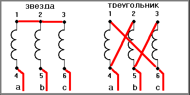
And, indeed, he had no less advantages than the usual three-phase current. It also generates a rotating magnetic field. Ah, because "born" it is a three-phase asynchronous motor, it is ideally suited as a working current for three-phase asynchronous motors. Among other things, it was possible to reduce the line voltage to 220 V, as well as bring its own power consumption to 200 watts. All consumers connected to such a converter can be connected both with a "star" and a "triangle" Fig.5.
Fig.5 Connecting consumers to the converter.
I want to add that my converter has been used in private households for about 12 years. Three-phase consumers work from it:
– electric sawmill with a power of 2.8 kW;
– a grain grinder with a power of 1 kW;
- electric grinder, 400 watts.
I helped my work colleague make the same converter. It has three-phase functioning flawlessly:
– electric drill, power 1 kW;
– small-sized concrete mixer, power 500 W;
– a grain grinder with a power of 1.2 kW;
– electric jointer, power 0.6 kW.
Of course, three-phase electric motors from a single-phase network will consume exactly as much energy when working through a converter as it is written in their passport (the law of conservation of energy cannot be deceived!).
In conclusion, I would like to give a few practical advice for those who want to repeat the design of the converter (and forever forget about all the problems associated with the operation of three-phase electric motors in single-phase networks):
The power of the electric motor used as a converter must be greater than the power of the electric drive connected to it. For example, if a 4kW motor is used in the inverter, the connected motors should be less than or equal to 3kW;
Practice has shown that a 4 kW converter can solve all the “problems” of a personal household. In addition, the load on the network within 2-3 kW is quite acceptable;
The current consumed by the converter in the operating mode must not exceed the rating current for this type of electric motors (otherwise the converter may burn out);
It is better to use “low-speed” electric motors (synchronous speed of 1000 rpm or less) as electric motor-converters. They are very easy to start, and the ratio of the starting current to the working one, as a rule, is less than that of high-speed ones, and therefore the load on the network is “softer”.
The order of work with the converter should be as follows: the converter starts first, then the three-phase current consumers. Switching off is carried out in the reverse order.
Capacitors of the type MBGO, MBGP, MBGT, K-42-4, etc. for an operating voltage of at least 600 V can be used as a starting capacitor Sp. It is not desirable to use electrolytic capacitors. The capacity of the starting capacitor Sp is determined by the power of the converter. For 4-kilowatt converters, it is approximately equal to 60-80 uF. It is selected experimentally, starting from the upper limit:
Sp=2800 If/Uс,
Where Iph is the rated phase current of the converter, A,
Uс - voltage of a single-phase network, V.
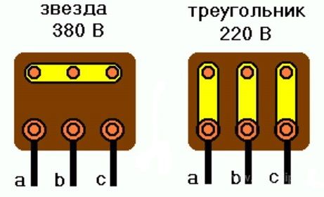
Connection diagrams for the stator windings of a three-phase asynchronous motor: a - into a star, b - into a triangle, c - into a star and a triangle on the motor terminal board
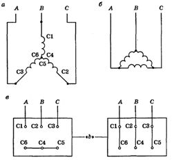
C1, C2, C3 - the beginning of the windings, C4, C5, C6 - the end of the windings. But now more and more new labeling of conclusions is being used. U1, V1, W1 - the beginning of the windings, U2, V2, W2 - the end of the windings.
According to GOST, the windings of an asynchronous motor have the following designations: Phase I - C1 (beginning), C4 (end), Phase II - C2 (beginning), C5 (end), Phase III - C3 (beginning), C6 (end).
But why an additional motor, if you can make our three-phase one rotate from one? To do this, you only need to do two simple conditions- apply single-phase voltage to one of the windings and “push” the rotor, since it will not start from one phase. How to push? As you like, even with your hands on the shaft - without a load, this is easy to do. But, of course, we will save our hands, and we will push using the most common scheme - a starting capacitor.
The capacitance of this capacitor does not have to be large - without load, as I said, the generator is easy to start even with your hands. As soon as rotation begins, our motor-generator will spin merrily from one phase, producing the missing two with its “extra” windings. The only drawback of such a circuit is a decent phase imbalance, which can be eliminated by turning on an autotransformer (see diagram).
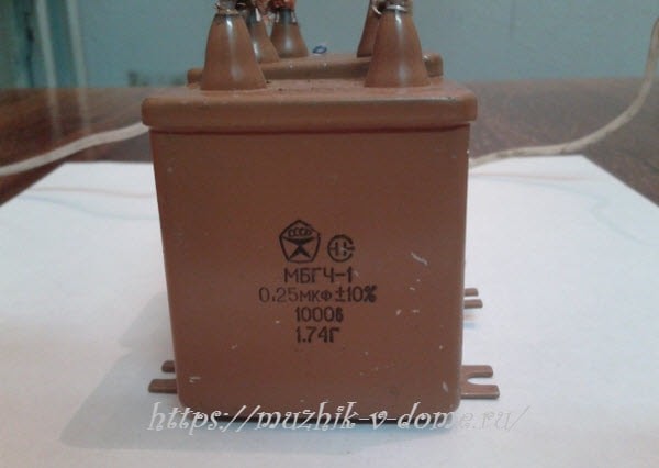
As an autotransformer, the author used the stator of a burned-out 17 kW electric motor (one magnetic circuit, the winding must be removed), on which he wound 400 turns of wire with a cross section of 6 mm 2 with a tap every 40 turns. Taps are used to fine-tune the phase voltage. A 4 kW engine was used as a generator, while the load power can reach 3 kW. A capacitor with a capacity of 39 microfarads, you can use MBGO, MBGP, MBGT, K42-4 for a voltage of at least 600V or MBGCH for a voltage of 250V. You need to turn on the generator without load, turn it off, of course, too.
Frequency converters 220-380 V make it possible to operate a three-phase motor at full power, gently adjust the speed, turn on the reverse rotation of the rotor. Such converters are used in industrial conditions, at various enterprises. They have the following advantages:
- energy savings, as power increases by 40-50%;
- continuous operation - voltage drops do not affect the operation of the equipment;
- increase in service life - soft start-up and braking reduce the degree of wear of equipment.
AT modern world electrical enthusiasts and owners of their farmstead are interested in using a 3-phase asynchronous motor in a single-phase network. Such engines are simple in design and do not require special costs in operation. This gives them great use among hobbyists. However, the use of 3-phase motors in a single-phase network is not always without difficulties. Three-phase current causes a magnetic field that rotates, gives a torque to the motor shaft. The current with one phase forms a ripple field that cannot rotate the motor rotor. It needs to be converted into a multi-phase one and then fed to an electric motor. Now there are many methods of change. They are not without drawbacks:
- It is impossible to get three-phase power without interference (with a phase difference of 120 degrees). Significant loss of engine power.
- Frequency converters of 1-phase current from 220 to 380 volts are not universal. They are made for a specific motor, limited in power. There are also electric motors that cannot be started by these methods in a single-phase network.
- Power capacitors for starting the engine (reactive elements) are inconvenient to use. The system becomes big, dangerous at home.
Advantages of the frequency converter
Universal power frequency converters idd from single-phase current 220 volts to three-phase current 380 volts are made on the basis of a simple three-phase electric motor have a number of advantages:
- Can generate three-phase current of 380 volts of voltage.
- An asynchronous motor does not lose power.
- It is applied for different types motors with any characteristics (restriction only on the network, power is not more than 7 kilowatts).
- Has a simple design. People with secondary education may well do it in a couple of hours. Will need an engine asynchronous type three-phase 4 kilowatts, capacitance 50 microfarads, pieces of wire, three phases. The electric motor does not need to be modified.
- The power consumption from the network is small. A 4 kW power engine at idle takes about 200 watts from the network.
Main working conditions
The synchronous 3-phase current generator has fixed coils and an armature. Coils are offset by 120 degrees. The power supply unit rotates the rotor, its variable flux of magnetic energy creates an inductive EMF in the stator windings. When connecting the stator coils to the motor, a 3-phase power current appears in the circuit. It can be used at home.
How, having one phase, add the other two? We take a simple electric motor of power of an asynchronous type with three phases with a closed rotor. It has a rotor and 3 stator windings, which are shifted at an angle of 120 degrees. We connect 1-phase current to one winding. The motor rotor will not rotate. And if by another force to give him some rotary motion, then it will begin to rotate due to the voltage of the changing current with one phase in the 1st winding. The rotor rotates electromotive force induction in the remaining windings, forms the other two phases. We get a rotating transformer. One winding of the motor, to which the changing 1-phase power current flows through the network, will be the excitation winding, which forms the magnetic field of the rotation rotor, and it gives the excitation of the alternating voltage in other windings.
This voltage turns out to be 3-phase because the electric motor has an effect. On the remaining windings, the voltage is reduced compared to the excitation winding (due to converter losses). This difference is about 15 volts and is determined by the design features of the electric motor.
How can I make the rotor rotate from 1-phase voltage? It can be different. The use of a start capacitor circuit is recommended. The capacitance power value is small, because the rotor of the asynchronous type converter rotates without load. For the operation of the converter with a motor of 4 kilowatts, 60 microfarads is enough. With all the good results, there are also disadvantages of frequency converters:
- The voltage potential is dangerous for people 380 volts. To reduce the risk of electric shock, use 220 volt line voltage.
- The energy consumption of the 220 to 380 volt converter was noticeable. This reduced its efficiency at idle.
The system was gradually modernized, leaving the shortcomings. Instead of a power converter, an electric motor of 4 kilowatts of asynchronous type with a six-pole stator winding was used. These windings were included in a star for a linear voltage of 380 volts. We connected them to 220 volts (127 volts formed between zero and phase).
The start capacitor is turned off after the drive starts, although it is not always necessary to turn it off. It almost does not affect the operation of the entire structure. It turns out a star with an asymmetric arrangement. converters two phases and zero. This current is also called quasi-three-phase.
In fact, he has little positive, compared to the usual three phase current. Chastotnik creates a field of magnetic rotation. Frequency converters are made from a three-phase asynchronous type motor, matched with the operating current for such motors. It turned out to reduce the voltage to 220 volts, to make its energy consumption 200 watts of power. All devices can be turned on with a triangle and a star.
On our test subjects frequency converters voltage 220 to 380 volts, the following consumers operate in three phases:
- Circular saw 2.7 kW;
- Grain 1.2 kW;
- Emery 0.4 kW;
On another converter, other consumers also work successfully:
- Drill electric 1.5 kW;
- Construction concrete mixer 600 W;
- Electric planer 0.7 kW.
Three-phase electric motors, when operating in a single-phase network, use the same amount of energy as according to the frequency converter's passport, this is the conservation of energy according to the law.
If you give instructions on repeating the design of frequency converters, then you can forget about the problems in operating the frequency converter motors from a 220 volt network, although the motors themselves are made at 380 volts.
The power of the electric motor, which is used by the frequency converter itself, may be higher than the power of the electric drive connected to it. If the converter uses a 4.5 kW electric motor, then the power of the electric motors connected to it cannot be more than 3 kW.
Life shows that 4 kilowatts solves many issues of work. Network load up to 3 kilowatts is quite normal.
The consumed current in the operating mode cannot be higher than the current parameters according to the passport for this type of electric motors (otherwise the 220 to 380 converter will fail.
Electric motors for converters are most often used with low rotational speeds (up to 1000 revolutions). They start softly and have a lower ratio of starting current to running current than high-speed motors, which means less stress on the wiring.
The starting sequence should be as follows: first, the frequency converter is turned on, then the motors of the 3-phase motor. Disable in reverse order.
Instead of a start-up capacitor, the following types are used: MBGT, MBGO, K-42-4 with an operating voltage of more than 600 volts. The use of electrolyte capacitors is not recommended. The capacitance size of the start capacitor is calculated from the power at 380 volts. For example, for a 4 kW converter, the capacitance is 80 microfarads.
Connection diagrams for the stator windings of a 3-phase asynchronous motor: a - star, b - triangle, c - star and triangle on the terminal board of the frequency converter of the electric motor.
C1, C2, C3 - the beginning of the winding, C4, C5, C6 - the end of the winding. Often used output marking U1, V1, W1 - the beginning of the winding, U2, V2, W2 - the end of the winding.
According to the standard, the winding of an asynchronous motor is designated: Phase I - C1 start, C4 end, Phase II - C2 start, C5 end, Phase III - C3 start, C6 end.
If there is an asynchronous motor with three phases with a short-circuited rotor, then it is easy to make three phases from one. To do this, you must force it to work as a generator. The chastotnik generator must be rotated so that it begins to produce current and voltage. This means that one more motor with one phase will be needed, compatible in terms of power, with the required speed.
But do we need another chastotnik electric motor if we can force a 3-phase electric motor to work from one phase? It is necessary to create two conditions: turn on the voltage with one phase on one winding and turn the motor, because it will not work with one phase. What needs to be done for this? You can run it manually, it's easy. And you can use a starting capacitor for this purpose.
The capacitance size of the starting capacitor can be small, since it starts easily without loading. At the start of rotation, frequency converters will easily start from the 1st phase. The frequency converter will create the remaining two windings with its additional windings. One disadvantage of such a connection scheme is the phase imbalance, which can be corrected by adding an autotransformer to the circuit.
For this, a chastotnik can be used instead of an autotransformer, the stator of a failed electric motor for 15 kilowatts (only a magnetic circuit), it made 380 turns of wire with a cross section of 6 mm 2 with an output of 40 turns. Conclusions are needed for a good preparation of the potential for the phase. You can use a chastotnik as a generator for a 4 kilowatt motor, we take a load of up to 3 kilowatts. We take the starting capacitor of the MBGP, MBGO type for a capacity of 40 microfarads, a voltage of more than 600 volts. It is necessary to connect the chastotnik generator without load, turn it off as well.
Frequency converters 220 to 380 V have been used for a long time, but there is no good information about them, even among specialists servicing electric motors. Many who have their own household, workshop, garage, had to deal with starting the engine. For some, frequency converters will be able to assist in saving electricity, making life and work easier. Such converters have long needed to be household appliances in the home and household.
Content:Very often in domestic conditions there is a need to use equipment where the drive is. In this regard, the problem arises of how to make 380 volts from 220. Most often in practice, inverters are used - special devices for converting voltage. The converters regulate the voltage consumption to the optimum level and can change the frequency of the drive.
Using voltage converters
In modern residential buildings, the distribution of electricity to apartments is carried out using single-phase AC networks, with a voltage of 220 volts. However, sometimes it becomes necessary to obtain a voltage of 380 volts to power household metal and woodworking machines that allow processing small parts.
For these purposes, a 220 to 380v voltage converter is required, which is widely known as an inverter. In addition to performing basic functions, the converter also regulates the frequency of motors. This measure contributes to a significant reduction in electricity consumption compared to equipment whose frequency remains unchanged. The principle of operation of inverter devices is based on the method of double frequency conversion. As a result, a three-phase linear system voltage 220 volts.
Converter device includes protective system, warning the likelihood of overloads in current strength and short circuit. In addition, the inverter is protected from overheating. The use of modern models of these devices contributes to the smooth start-up of motors when the starting voltage increases in relation to the phase current. This ratio is a constant value.
Due to their low weight and small overall dimensions, inverters are easily transported from place to place, which has great importance when using them at home. However, despite all the advantages, the converters have one significant drawback - too high a cost. Therefore, if three-phase equipment is rarely used, the purchase of an inverter will not be economically feasible.
Three phase method
There are other ways to convert current without using an expensive inverter. One of them is the method of using three phases from different power sources, with a voltage of 220 volts. It has been known for a long time and allows you to successfully receive 380 volts. However, in urban areas, the use of this method requires prior approval from the organization of energy supervision.
If you have a three-phase switchboard, you don't have to think about how to convert the voltage. Such a shield is available in each entrance of an apartment building, which allows you to directly connect any three-phase equipment. the only technical condition such a connection will have a three-phase extension cord.
Application of three-phase transformer
To successfully convert the voltage in this way, you will need a three-phase transformer with the most suitable power, rated for 220/380 volts. With it, you can make 380 volts from 220.
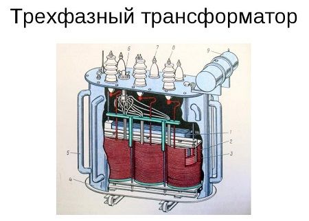
First of all, you need to connect the network windings. Then the mains voltage is applied directly to two terminals, and to the third terminal through a capacitor designed to work with alternating current and a voltage of at least 400 volts. The approximate capacitance of the capacitor is selected in the ratio of 7 microfarads per 100 watts of engine power. In the future, this indicator can be adjusted so that the output load on all three phases is the same.
It is forbidden to turn on the transformer without load. To turn on, you can use a push-button post and a magnetic starter.
This question was asked by those who, for some reason, fell into the hands of three-phase motor. The thing seems to be necessary, not cheap, but how to connect a three-phase motor to single-phase network- unclear.
This is not difficult to do, it is enough to have "straight" hands and a few additional details. You need to understand right away that you cannot get the full power that this engine can develop in a 380 V network. So, there are two connection schemes.
The first, and most often used, is the connection to the "triangle".
Delta connection
Here, all three windings are connected in series, one after the other. Thus, there are three ends with leads from each winding. Due to the fact that each winding is designed for 220 volts, by connecting them in parallel with the network, you can get the maximum possible power. Since there are only two outlets in the socket network, the third phase is simulated by a wire connected to the capacitor. Second end phase-shifting capacitor, connected to the phase or zero of the outlet. Which conductor of them this end will be connected to depends on the direction of rotation of the motor.
The second way to connect is to the "star".
Star connection
It is less effective than the first and is used only when it is not possible to assemble the windings in a different way. The fact is that the ends of the motor windings go into the so-called brno, that is, a box at the top of the case, in which there is a terminal for connecting wires. Most often, there are only three ends on the terminal, that is, a star connection. It is not possible to redo this due to the fact that the wiring is done inside the case, where there is no access. When there are six ends on the terminal, by changing the location of the jumpers, you can change the circuit.
Let's go back to the star connection. As already mentioned, each winding is designed for 220 volts, and since the mains voltage passes in series through two windings, each has exactly half - 110 volts. Hence the loss of power three times. In a delta connection, the power drops by only 30%. But this does not mean that the engine assembled by a star is useless. It can be successfully used in garage needs. For example, you can make a good emery machine, sharpen something, for example, a knife, the power will be enough.
As for the working capacitor, that is, what will be permanently connected in the motor circuit, its capacity is considered as follows: 0.1 kW of the motor = 7 microfarads. For example, we have a 2 kW motor, 7 * 20 \u003d 140 microfarads. This will be the working capacity. Sometimes it is necessary, in addition to the working capacitor, to have a capacitance for starting. This is necessary when the motor is used in heavy starting equipment. For example, ventilation with a massive snail. The engine will not be able to gain momentum only on working capacitors, and the use of an overestimated working capacity will lead to excessive heating of the engine. Therefore, the use of capacitors for starting is simply necessary. 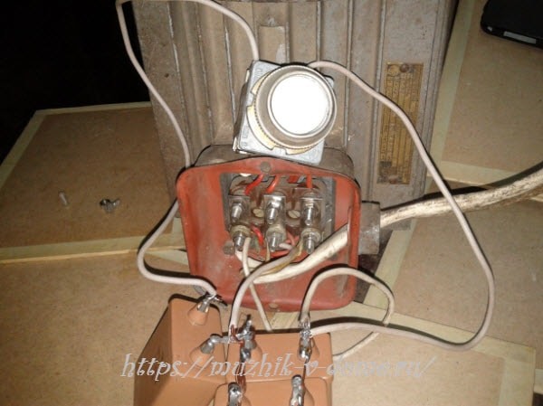
How do they work? At the moment of starting, with the help of a button, in parallel with the working capacitors, the starting capacitance is turned on. As soon as the engine has reached full speed, the button is released and only working tanks remain in use.
The starting capacity should be three times the working capacity. But this does not mean that having a 140 uF capacitor, you need 420. Here it means that at the time of start, the total capacitance (both working and starting in parallel) should be 420 uF, and the starting capacitor itself, separately, should have a capacitance 280 uF.
It is unlikely to find one capacitor of such a capacity, therefore, most often they take smaller ones and collect them in parallel. Then the capacity of each is summed up, and as a result we get the total. 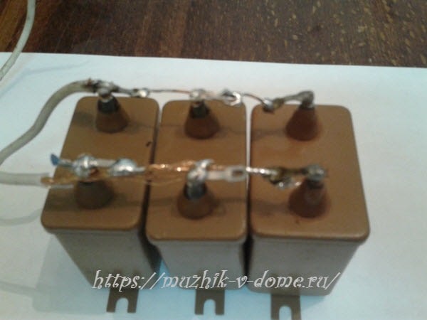
In addition to capacitance, you need to pay attention to the operating voltage of capacitors. It must be at least 400 volts. Do not take 250, although it is cheaper and the voltage is higher than the mains, they will quickly fail. In general, the higher the operating voltage of the device, the better.
Finally, a small reminder of the dangers of electricity. When making any changes to the circuit, turn off the voltage. The capacitor is capable of accumulating charge, so even when the power is turned off, voltage is present on it. For safety, discharge it, for example, with an incandescent lamp.


