Outdated computers, as well as any other old thing, detail, has such a property as breaking down, failing. As a rule, most of us are not particularly upset about this. "All the same, it's already an old thing, it can't cope with its tasks ...", etc. Although in most cases this thing can be safely reanimated, restored, repaired. Some simply do not have time to do this, others cannot for one reason or another, and others are simply too lazy.
This is where I got into trouble. There was a computer of the following configuration:
- MB: Soltek SL-65EP
- Processor: Intel Celeron 800 Mhz
- Memory: 2*128MB
- Video: GeForce Ti 4200
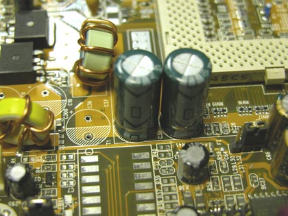
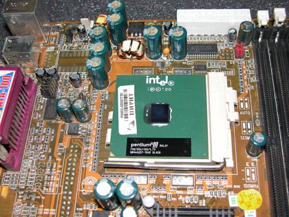
Photo 1. Leaking capacitors.
Of course, it was possible to immediately throw this motherboard into the trash, but after all, it worked normally six months ago ... and perhaps the same amount - if not more - will work. So you can try to revive the motherboard by replacing the capacitors with similar ones. If the experiment fails, then it’s not a pity - the computer can be considered not working anyway. But if it works out... Well, let's get down to business.First of all, you need to find out the capacitance and voltage of the leaked capacitors, and find, buy, solder similar capacitors. Because Since my work is related to the modernization, replacement and repair of computers and components, it will not be difficult to find a non-working motherboard with the capacitors I need. At my work, I found the motherboard I was looking for with the capacitors I needed (see photo 2), but for those who do not have such an opportunity, it makes sense to buy the required number of capacitors in the store. One moment, if you have already decided to change the swollen capacitors to new ones, then it makes sense to replace the rest with exactly the same ones. Although they are normal in appearance, it is better to immediately eliminate all the "bottlenecks". Those. in my case, I replaced all nine capacitors, seven of which were swollen. It is important! It is also worth noting that the capacitors must be changed to exactly the same in capacity, and the voltage may be slightly higher. I got the following replacement. Capacitors 1500 uF 6.3 volts I replaced with 1500 uF 10 volts .
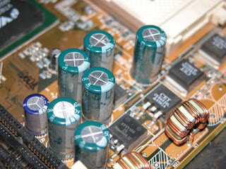
Photo 2. Donor motherboard.

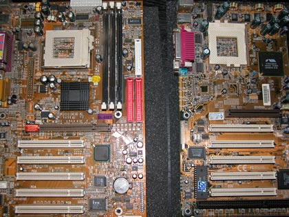
Photo 3. Patient and donor are ready for surgery.
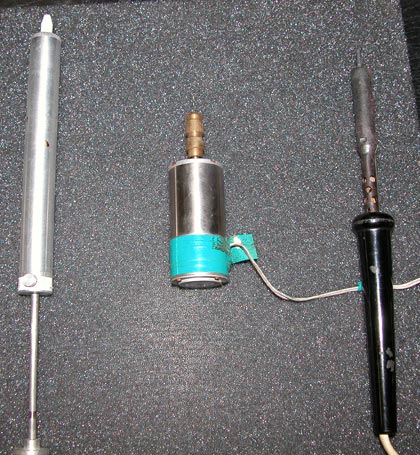
To carry out restoration work, we need to stock up on the following tool (see photo 4):
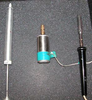
Photo 4. We prepare the tool.
- suction (pictured left)
- microdrill
- soldering iron with a thin tip and the ability to change power
- liquid rosin (ordinary rosin dissolved in alcohol)
- tin
- tweezers
- very thin screwdriver
- medium hard brush
- magnifying glass
- alcohol
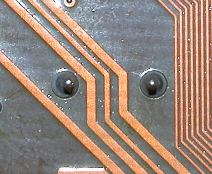
You should also pay attention that there will be some very inconvenient places on the motherboard in terms of the location of the capacitor leads relative to the printed tracks (see photo 5). Probably, it is not worth saying that in such places one must be extremely careful and accurate, because. a damaged track can undo all our work. Although I will not deny it, the damaged track itself can also be restored, but this will already be a very miniature work. So it would be better if the tracks remain safe and sound.

Photo 5. One of the very difficult places to solder.
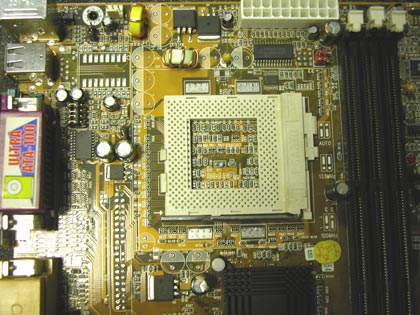
So, we soldered all the bad capacitors and did not damage anything (see photo 6). Most likely some - if not all - of the holes for the legs of the new capacitors will be filled with tin. That's just for that case, we need a micro-drill and a very thin drill. We drill holes very carefully and carefully. Which side of the motherboard is best for drilling? It's up to you to decide. There is no single answer. See for yourself where it is most convenient to crawl, where the tin has frozen in a convenient shape. But the fact remains that all holes filled with tin for capacitors must be drilled. Alternatively, you can try to use a soldering iron with a very thin tip and suction, but it will not be very convenient for one. If you used a micro-drill, brush off sawdust and shavings with a brush. You can also use a vacuum cleaner that has a blowing mode.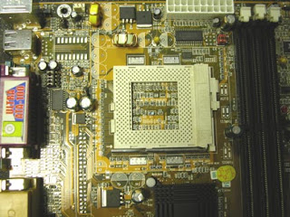
Photo 6. Motherboard without bad capacitors.
So the hardest part of the job is done. If you bought capacitors in a store or on the market, then you can safely skip this paragraph. We'll deal with soldering good capacitors. In principle, the soldering technology is exactly the same, with the only difference being that here we don't have to worry about the board, tracks, etc. The most important thing is not to overheat the capacitors themselves and not break off their legs. As my practice shows, there will be one or two more capacitors on the donor motherboard. But it’s better not to get carried away and just as carefully - very carefully - to solder them.Coming last phase resuscitation. We pick up a good capacitor and carefully insert its legs into the prepared holes. Pay attention to the marking of the capacitor and the seat. The white strip on the capacitor should be located on the shaded area of the seat (see photo 7). We smear the legs of the capacitor a little with liquid rosin and then we take a little tin on the soldering iron. With an accurate and accurate movement, we transfer the droplet to the leg. Due to the fact that we previously lubricated the leg with liquid rosin, the tin itself will spread evenly. If you still have dirty traces of rosin around the soldered lead after soldering, it does not matter. Here a small piece of matter, a thin screwdriver and alcohol will already help you. This is where a magnifying glass comes in handy. Using a magnifying glass, carefully inspect all soldering points for "tin nozzles" and other hand soldering products.
Outdated computers, as well as any other old thing, detail, has such a property as breaking down, failing. As a rule, most of us are not particularly upset about this. “It’s still an old thing, it doesn’t cope with its tasks ...”, etc. Although in most cases this thing can be safely reanimated, restored, repaired. Some simply do not have time to do this, others cannot for one reason or another, and others are simply too lazy.
This is where I got into trouble. My children had a computer of the following configuration:
- MB: SL-65EP
- Processor: Intel Celeron 800 Mhz
- Memory: 3*128MB
- Video: GeForce Ti 4200
The rest is not so important, because. As it will become clear further, the whole thing is in the motherboard. So, it all started with the fact that the computer began to spontaneously reboot. At first, it was simple, when no one did anything behind him for a long time, and then he began to go into overload during games. There was nothing so criminal in the system logs, so the thought immediately arose that the whole problem was in the hardware. The power supply fell off immediately, because. some time ago I changed it to a new 300W PowerMan. So it's either in the memory ("old" it is already PC133), or in the motherboard. I open the case and immediately find the problem. Almost all of them swelled up, and some even started to leak (I had a worse case, everything leaked out there). See photo 1.
Of course, it was possible to immediately throw this motherboard into the trash, but after all, it worked normally six months ago ... and perhaps the same amount - if not more - will work. So you can try to revive the motherboard by replacing the capacitors with similar ones. If the experiment fails, then it’s not a pity - the computer can be considered not working anyway. But if it works out... Well, let's get down to business.
First of all, you need to find out the capacitance and voltage of the leaked capacitors, and find, buy, solder similar capacitors. Because Since my work is related to the modernization, replacement and repair of computers and components, it will not be difficult to find a non-working motherboard with the capacitors I need. I found the one I was looking for with the capacitors I needed at work (see photo 2), but for those who do not have such an opportunity, it makes sense to buy the required number of capacitors in a store, for example, in a Chip and Dip store. One moment, if you have already decided to change swollen capacitors for new ones, then it makes sense to replace the rest with exactly the same ones. Although they are normal in appearance, it is better to immediately eliminate all the “bottlenecks”. Those. in my case, I replaced all nine capacitors, seven of which were swollen. It is important! It is also worth noting that the capacitors must be changed to exactly the same in capacity, and the voltage may be slightly higher. I got the following replacement. Capacitors 1500 uF 6.3 volts I replaced with 1500 uF 10 volts .

To carry out restoration work, we need to stock up on the following tool (see photo 4):
- suction (pictured left)
- microdrill
- soldering iron with a thin tip and the ability to change power
- liquid rosin (ordinary rosin dissolved in alcohol)
- tin
- tweezers
- very thin screwdriver
- medium hard brush
- powerful magnifying glass
- alcohol
- straight arms and a bright head (if you are on a soldering iron, ask a familiar radio amateur)
First, it makes sense to vacuum and clean the used motherboard from dust (it’s not pleasant to work with a dusty and dirty “mother”). And then we will deal with soldering swollen capacitors. This must be done very carefully and carefully in relation to the board and printed tracks, because. this motherboard will still serve us faithfully. Tin used for soldering on a conveyor is more refractory than what you have available. Personally, I did the following. With a heated soldering iron I take some tin and warm up the leg of the capacitor, as soon as my tin is mixed with the factory one, I apply the suction mentioned earlier. Ideally, the leg and hole should be completely free of tin. If this did not happen and the capacitor stubbornly does not want to come out of the holes, you need to warm up the leg a little and gently shake the capacitor with your finger. After that, he should calmly get out. By the way, you can first practice on some old and unnecessary board. A couple of three soldered elements should be enough.
You should also pay attention that there will be some very inconvenient places on the motherboard in terms of the location of the capacitor leads relative to the printed tracks (see photo 5). Probably, it is not worth saying that in such places one must be extremely careful and accurate, because. a damaged track can undo all our work. Although I will not deny it, the damaged track itself can also be restored, but this will already be a very miniature work. So it would be better if the tracks remain safe and sound.
So, we soldered all the bad capacitors and did not damage anything (see photo 6). Most likely some - if not all - of the holes for the legs of the new capacitors will be filled with tin. That's just for that case, we need a micro-drill and a very thin drill. We drill holes very carefully and carefully. Which side of the motherboard is best for drilling? It's up to you to decide. There is no single answer. See for yourself where it is most convenient to crawl, where the tin has frozen in a convenient shape. But the fact remains that all holes filled with tin for capacitors must be drilled. Alternatively, you can try to use a soldering iron with a very thin tip and suction, but it will not be very convenient for one. If you used a micro-drill, brush off sawdust and shavings with a brush. You can also use a vacuum cleaner that has a blowing mode.
So the hardest part of the job is done. If you bought capacitors in a store or on the market, then you can safely skip this paragraph. We'll deal with soldering good capacitors. In principle, the soldering technology is exactly the same, with the only difference being that here we don't have to worry about the board, tracks, etc. The most important thing is not to overheat the capacitors themselves and not break off their legs. As my practice shows, there will be one or two more capacitors on the donor motherboard. But it’s better not to get carried away and just as carefully - very carefully - to solder them.
The last phase of resuscitation is coming. We pick up a good (purchased or soldered) capacitor and carefully insert its legs into the prepared holes. Pay attention to the marking of the capacitor and the seat. The white strip on the capacitor should be located on the shaded area of the seat (see photo 7). We smear the legs of the capacitor a little with liquid rosin and then we take a little tin on the soldering iron. With an accurate and accurate movement, we transfer the droplet to the leg. Due to the fact that we previously lubricated the leg with liquid rosin, the tin itself will spread evenly. The main thing is not to overdo it with rosin. If you still have dirty traces of rosin around the soldered lead after soldering, it does not matter. Here a small piece of matter, a thin screwdriver and alcohol will already help you. Alternatively, you can use cotton swabs, but then you have to get rid of the hairs that cotton wool will leave on the conclusions anyway. This is where a magnifying glass comes in handy. Using a magnifying glass, carefully inspect all soldering points for “tin nozzles” and other hand soldering products. Although if you are a robot and your hands are not shaking from tension, you will not need a magnifying glass at all.
That's practically all. All swollen capacitors have been replaced, the board has been cleaned of rosin. It remains only to once again carefully examine the motherboard on both sides and you can return the patient to your workplace(see photo 8), having previously cleaned the case and components from dust. In a word, to do a little cleaning in the hull, anyway, we took out almost all the details, and once again it will never hurt to bring cleanliness and order to the hull.
In my practice, I have already revived three motherboards in this way (all of the same brand and the same company). What can I say, after this operation, the children's computer has been working normally for more than a year, no spontaneous reboots were observed anymore. But what is the reason for the failure of capacitors, I find it difficult to say, it is quite possible that they brought a defective batch of capacitors to the Soltek factory, in which the marriage manifested itself only after some time of operation.
So maybe you should not throw out old things, but try to repair them yourself, or offer to repair it to someone who knows how to do it and will do it.
The cost of repairing and replacing the south bridge
| Types of jobs | Price |
|---|---|
| Diagnostics | 0 rub. |
| Replacing power connectors with cost of parts | 1800-2200 rub. |
| Replacement of port connectors and other connectors with the cost of parts | 1500-2500 rub. |
| Replacement of other controllers with cost of parts | from 3000 rub. |
| Replacement of power circuits, secondary sources with the cost of parts | from 3000 rub. |
| Difficult to diagnose faults with the cost of parts | from 4000 rub. |
| Battery Charging Diagram with Parts Cost | 3500-5000 rub. |
| After an unsuccessful repair in another service with the cost of parts | from 4000 rub. |
| Replacement work | 1000 rub. |
|
Why is it worth contacting us? |
|||
|---|---|---|---|
|
Free visit and diagnostics. |
You have a guarantee for all services up to 2 years. |
We will refund your money if we cannot solve your problem. |
|
The motherboard is the most complex and valuable part of a laptop. In the system unit, many elements and microcircuits are connected to it through connectors and cables. In a laptop, they are integrated so that the design is as compact and economical as possible. Because of this, if the microcircuit is damaged, diagnosing and repairing the motherboard is a time-consuming task. Boards of different models are rarely interchangeable. Therefore, the laptop should be handled with care and cleaned regularly.
Any breakage of a part of the motherboard immediately affects the operation of the laptop.
Typical symptoms:
- The laptop does not turn on at all.
- The laptop turns on, but is unstable, often reboots.
- No power, battery not charging, laptop with battery not working.
- Peripherals do not work: USB ports, keyboard, mouse, touchpad, drive, Wi-Fi.
- The power supply indicator blinks.
- The power cord gets very hot.
- Clicks of an exfoliated chip crystal are heard in the case.
By itself, the motherboard does not fail. The cause of its damage is overheating, dustiness, flooding with liquid, dropping the laptop, hitting it. The use of "non-native" power supplies is detrimental, homemade devices, voltage drops, unskilled equipment setup and adjustment.
Types of motherboard repairs in laptops
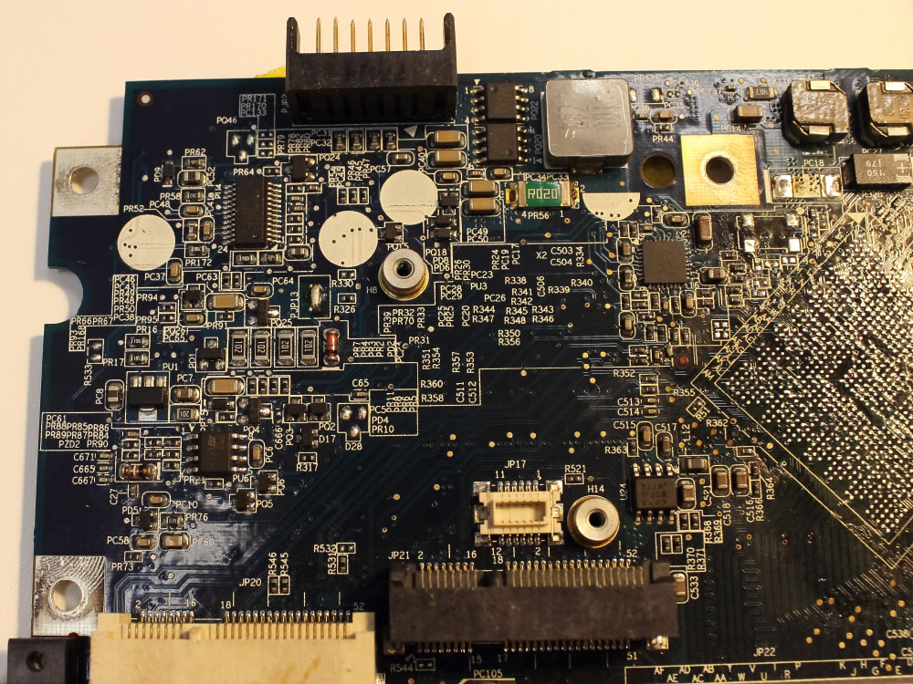
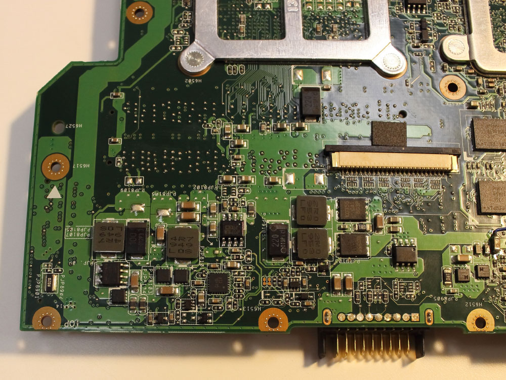
Accurate diagnostics reveals a failed element. To carry it out, modern diagnostic tools and a motherboard diagram supplied by the manufacturer to the laptop are required. Most burned-out microcircuits are visually identified by soot around the contacts on the back of the board. A damaged northbridge does not give such a "hint".
![]()
Our workshop performs all types of motherboard repairs:
- Repair of the logic and computing part - bridges north, south, video bridge.
- Repair of the power circuit - wide-pulse controller, multicontroller, charger, voltage stabilizer, LAN.>
- Repair, replacement of interface connectors - LPT, keyboard, mouse, AUDIO, VIDEO, PCI-X, AGP, PCI, tracks.
- Repair, replacement of cables and connectors USB, Wi-Fi.
We advise you to read
 Psychological characteristics of children in adolescence
 Transferring a child to another school - the procedure and necessary documents Whether to transfer a child to another school
, diagnosis, treatment Treatment of urogenital chlamydia") Chlamydia urogenital - description, causes, symptoms (signs), diagnosis, treatment Treatment of urogenital chlamydia
Chlamydia urogenital - description, causes, symptoms (signs), diagnosis, treatment Treatment of urogenital chlamydia The benefits and significance of hydroamino acid threonine for the human body L threonine what

