In pursuit of convenience and economy, lighting control schemes are constantly being improved. Now lighting, and indeed all electrical equipment in the house, can be controlled from the other side of the Earth.
This, of course, requires serious capital investments and the participation of highly specialized specialists. But there are control schemes that are quite possible to implement with a minimum set of knowledge in electrical engineering and which will greatly facilitate your life and save money. We will talk about these schemes in our article.
Manual circuits
All lighting control schemes can be divided into manual and automatic. Although manual circuits do not provide automation, they provide proper comfort. And in many cases, in terms of price and convenience, they have an undeniable advantage over fully automatic schemes.
Through and cross switches
Pass-through and cross switches have been used in practice for a long time. But the scope of their application can be much wider. After all, the installation of such switching devices allows you to control the lighting from two, three (see) and more places.
So:
- A through switch differs from a conventional switch in that it has one input and two outputs. Let the input be contact number 1, and the output be contacts numbers 2 and 3. In one position of the switch, contacts 1 and 2 are closed, and in the second position of the switch, contacts 1 and 3 are closed.
- The cross switch has two input contacts 1 and 2, as well as two output contacts 3 and 4. In one position of the switch, contacts 1 - 3 and 2 - 4 are closed, and in the second position contacts 1 - 4 and 2 - 3 are closed.
- This feature allows the switches to control lighting regardless of the position of other switches in the circuit. In this regard, such a scheme is often called a corridor.
- As you can see in the diagram, only feed-through switches can be used to control with two switches. For more control points, it is required to use already cross switches.
- In order to implement this scheme for two switches, the following switchings should be made. Connect the phase wire from the junction box to the input of the first switch.
- After that, we connect the outputs 2 and 3 of both switches. And we connect our lamp to the input of the second switch. It remains to connect the neutral wire to the lamp directly from the junction box and our circuit is ready to go.
- To create a similar circuit for three or more switches, cross switches should be placed between two walk-throughs. In this case, we connect wires from terminals 2 and 3 of the first through switch to inputs 1 and 2 of the cross switch. And from pins 3 and 4 of the cross switch we connect to pins 2 and 3 of the pass switch. The rest of the scheme remains unchanged.
Schemes on an impulse relay
But let's be frank, the circuits of through-and-cross switches are becoming obsolete. With the advent of impulse relays, such circuits seem overly complex and not reliable enough due to the large number of contacts.
It is easier to use impulse relays, which are more convenient for lighting control and whose circuits are much simpler.
- The principle of operation of the impulse relay is as follows. When power is applied to the coil, the power contacts change their state to the opposite and are fixed in this state. This allows a short-term voltage supply of 0.1 - 0.5 seconds to turn the lighting on and off.
- Since fixing the position of the switch in this case is not required, ordinary buttons are used to work with a pulse relay. Such as for doorbell. A simple push of a button turns on the light. Pressing this or any other button in the chain again will disable it.
Note! When choosing an impulse relay, make sure that the coil is powered by 220V. In addition, you should choose the right rated current primary circuit, which for the lighting network must be at least 6A.
- In addition to triggering from impulses, most relays have the function of only turning off and only turning on the lighting. For some circuits, this can be a very useful feature.
- Due to such a rich functionality of the relay, it has as many as six contacts. Typically, the control outputs are located on top, and the power outputs are on the bottom. But, unfortunately, there is no single system here, and each manufacturer is sold out as he considers right. The same is true with the designation of contacts. Therefore, in order not to be unfounded, we will take the principle of designating one of the most common manufacturers. An example is the relay - RIO-1.
- If you are going to connect an impulse relay with your own hands, then first of all we collect a control signal. To do this, we connect the phase wire from the junction box to each switch without fixing. We collect the outputs from the switches in series and connect them to the “Y” contact on the impulse relay.
- But for the relay to work, we need the presence of power on the coil. We supply this power by connecting the phase wire from the junction box to terminal "11", and the neutral wire to terminal "N".
- Now from terminal "14" we take a phase wire to our lamps. Zero, respectively, we lay from the junction box. All our circuits are fully operational.
- If you have a desire to install a button that will only turn on the lighting when pressed, then we connect this button to the “Y1” contact of the impulse relay. Accordingly, the button that works only to turn off the light is connected to the contact "Y2" of the relay.
Connecting lighting through a starter
According to clause 6.2.10 of the PUE, it is forbidden to power more than 20 lamps or multi-lamp lamps from one group machine. But sometimes it is necessary to turn on a larger number of lighting fixtures at once.
In this case, the lighting control circuit and circuit must provide for the installation of a starter or contactor.
So:
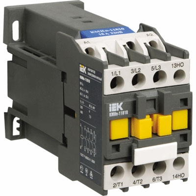
- The starter is a coil, a magnetic circuit and a system of power and secondary contacts associated with it. The magnetic circuit is divided into a fixed part and a moving part. When voltage is applied to the coil, the movable part of the magnetic circuit is pulled up to the fixed part. At the same time, their position and contacts change. When the voltage on the coil disappears, the magnetic circuit under the action of the springs disappears, respectively, the contact part also disappears.
Note! Typically, the starter has three power contacts. This allows you to connect one lighting group to each of them, which in turn allows you to simultaneously turn on up to 60 lamps.
- A push-button post is usually used to control the starter. It must have at least two buttons "on" and "off". The "on" button has normally open contacts, and the "off" button has normally closed contacts.
- In order for the lighting to be controlled through a contactor or starter, we, as in the impulse relay circuit, should assemble a separate power circuit and a separate control circuit. The power circuit is assembled quite simply. To do this, it is enough to connect the phase wires from the group machines to the input power contacts, and the phase wires going directly to the lamps to the starter outputs.
- But with the control scheme, everything is a little more complicated. To do this, we take a phase wire from one of their group machines and connect it to one of the contacts of the "off" button. From the second contact of the "off" button, we connect the wire to the first contact of the "on" button. From the second contact of the “on” button, we forward the wire to the phase of the starter coil. We connect the second output of the starter coil to zero.
- It would seem, that's all. When the “on” button is pressed, voltage will appear on the coil and the starter will work. But the fact is that as soon as we release the “on” button, the starter will disappear. Therefore, we need the so-called self-pickup scheme.
- The essence of this scheme is as follows. In addition to the power ones, the starter has secondary contacts that repeat the movement of the power ones. There are normally closed and normally open contacts.
- To implement the self-pickup circuit, we take the phase from the starter coil. We connect it to the normally open contact of the starter. To the second output of this contact we connect the wire that goes to the "off" button. Here we connect it to the contact between the button "on" and "off". Now the starter will work even after releasing the "on" button.
- This scheme works in this way. Through the normally closed contact of the "off" button, voltage is supplied to the "on" button. When the "on" button is pressed, voltage is applied to the coil and the starter is triggered. In this case, the secondary contacts of the starter are closed, thereby shunting the "on" button. When the "off" button is pressed, the voltage is removed from the coil, the starter disappears, and the circuit returns to its original state.
Schemes with automatic control
But be that as it may, manual control schemes require human participation. And this is not always possible or comfortable.
It is much more convenient if the lighting turns on independently for certain factors. For this, a circuit is also used that assumes the presence of special sensors.
Scheme with light sensors
For a more rational use of electricity, so-called light sensors are used. They allow you to turn on the lights only when the level drops. natural light to the set parameters.
At the same time, they do not require human participation at all, and their maintenance is reduced to periodic wiping of the sensor photocell from dust.
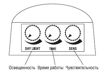
The principle of operation of the light sensor is reduced to fixing the level of illumination with a special photocell. When the set parameters are reached, it works and supplies voltage to the lighting network through the power contact. Adjustment of the required level of illumination is realized by a special regulator on the outer surface of the housing.
Connecting a light sensor does not require special knowledge:
- First of all, we connect the phase and zero to the corresponding sensor terminals. They may be designated as "L" or "L1" and "N". This connection keeps the device operational.
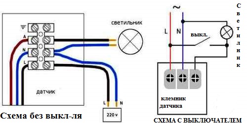
- From the third, not yet involved output, we connect the lamps. Zero for fixtures is taken in addition to the sensor, directly from the junction box.
Note! According to clause 6.5.7 of the PUE, all systems with automatic systems lighting controls must be able to be switched on manually. This is necessary for repair, operation of the network, as well as in case of sensor breakdown. This rule applies to all circuits with automatic control.
The outdoor lighting control scheme, for which such sensors are most often used, often involves connecting not luminaires from the sensor, but a lighting starter.
In this case, when the illumination decreases, the sensor is triggered, then the starter and voltage is applied to the lighting network, which is controlled either by other sensors or switches. This ensures that the lighting is switched on only when there is insufficient natural light.
Circuit with a timer
In some cases, lighting must be turned on after a certain time. In this case, the schema automatic control lighting is equipped with a timer.
So:
- There are two types of timers: analog, with a clock mechanism, and electronic, the principle of operation of which is similar to the principle of operation of an electronic watch. In addition, timers are divided into real-time devices and reverse reporting devices.
- Real-time devices keep track of time like a regular clock and, when a given time arrives, perform specified actions - turning on or off electrical equipment.
- Countdown devices often have a strictly regulated time period, during which it is possible to operate - an hour, a day, a week. In this case, you can set actions for not a limited time, but for a given time period. And the timer will keep track of the time until the trigger.
- By themselves, timers are practically not produced. Often they are integrated with other devices. These can be circuit breakers, sockets, switches, starters or other equipment.

- Modern timers have the ability to program not for one, but for several actions independent of each other. In addition, modern electronic timers can control several devices at once. But such devices are most often used in lighting schemes. smart House” and other high-tech schemes as in the video, which can be difficult to create without the help of professionals.
Scheme with motion sensors
Gives the highest degree of energy savings. The use of these devices allows you to turn on the lighting only while a person is in a room or area of responsibility.
In this case, no participation is required from the person himself. Even the most advanced microcontroller control circuits use this type of sensor to control lighting.
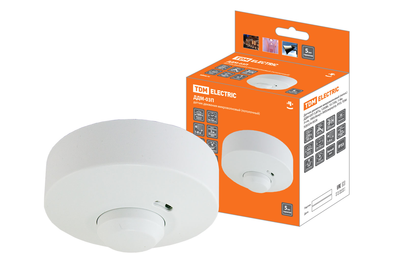
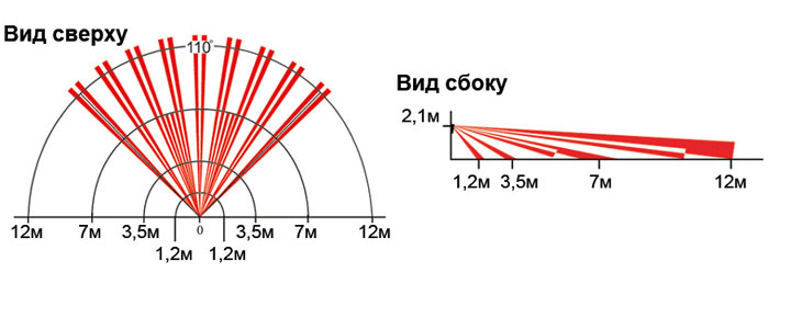
- The principle of operation of the motion sensor is based on fixing the infrared radiation emitted by a person. At the same time, in order to fix not only the presence of radiation, but also the movement of a person, there is a special optical system. As the person moves, the fixation of radiation in this system is carried out by different elements.
- The number of elements, the operation of which will lead to the operation of the sensor is regulated. Therefore, at the slightest movement, fixing with two elements is enough to trigger the sensor, and for a coarser adjustment, fixing with three or four elements may be required.
|
|
When choosing a motion sensor, you should pay attention to a number of parameters. First of all, these are electrical ratings. First of all, we are interested in the supply voltage, which should be 220V, as well as the rated current of the primary circuit. It can be 6, 10 or 16A. The higher this value, the more lamps we can power from the sensor. |
|
|
Most modern motion sensors have the ability to adjust the level of illumination for triggering, the sensor's operating time after triggering, and selecting the sensitivity of the trigger. |
|
|
An important parameter is the angle of the sensor. Most modern models are capable of providing an operating angle of up to 180⁰. And for ceiling-mounted sensors, 360⁰ zone coverage is normal. |
|
|
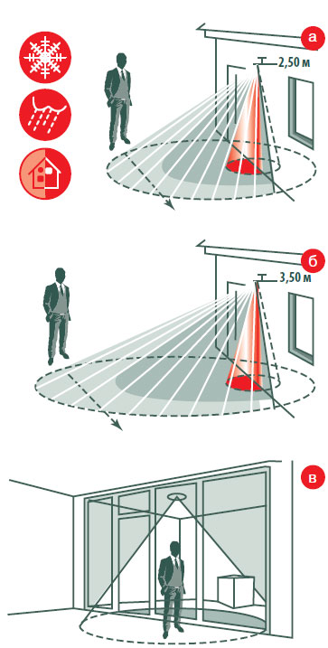
When setting up motion sensors, as well as their operation, it should be remembered that bad weather conditions significantly reduce their sensitivity. In addition, the installation of foreign objects or glass in front of the sensor can completely limit its operation. The same rule applies to climate equipment installed next to the sensor. |
|
|
Another important parameter is the level of protection of the motion sensor from the ingress of moisture and dust. If for indoor installation it is possible to choose devices without protection, then for outdoor installation it is better to choose products with IP 44 and higher. |

So:
- Connecting a motion sensor is quite similar to connecting a light sensor. In the same way, for the device to work, it needs a phase and a zero. To power the fixtures connected to it, a third wire is used. For the lighting network, it is phase.
- Besides, enough interesting solution is the possibility of their parallel connection. For example, we have a corridor with several entrances. Opposite each of them we put a motion sensor, and when at least one of them is triggered, the lighting of the entire corridor turns on. This is the so-called "or" logic.
- In view of the wide use of modern motion sensors, they have more opportunities than just motion detection. In most cases, they contain a built-in timer, and sometimes a light sensor.
- This allows you to significantly expand the range of their use and increase multitasking. For example, you can set a trigger condition for lowering the illumination level to a certain value and the appearance of movement. At the same time, the sensor should be in the triggered state for so many minutes after the movement stops in its coverage area.
- Of course, this is more convenient, but often increases the final cost of the entire lighting scheme. Therefore, our instruction for reducing the cost of the project advises integrating several different automatic and manual schemes with each other.
Conclusion
As you can see the modern scheme remote control lighting allows you to completely exclude a person or minimize his fate. But of course, the more perfect the scheme, the higher its final cost.
Therefore, not in all cases it is advisable to spend large sums of money on the automation of control systems. Sometimes you can get by with the good old switch. But of course it's up to you to decide, especially since now you know how to mount it all without outside help.
Electric lines that include originate from the main electrical panel, and each line consists of three conductors: phase, neutral wire and ground. All three conductors reach the end terminal of the luminaire, and if it has a metal case, the earth wire must be connected to the appropriate terminal.
During installation, each switchboard at least two lines of the lighting circuit should depart in parallel, in this case, if there is a malfunction on one of the lines, the entire object will not be plunged into darkness. The insulation of each conductor must be of a certain color, according to the generally accepted rule.
The phase wires should be brown or black, the neutral wires should be light blue, and the ground wire should be yellow or green.
Various constructs can be used to understand the wiring diagram, including the following:
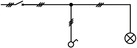
Single line diagram
The schemes are given in a simplified form. Such drawings show only the important elements of the circuit and contain information about their location, the number of conductors, and their cross section.
Analytical scheme
Which shows all the lines and their connections to different parts of the circuit. Such drawings on a large scale lose their readability.
Operating scheme
Which shows in detail the way electric current. This design method is descriptive and easy to read.
Running Lighting Circuits
One-line, analytical and operational diagrams
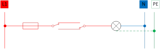
Simple Lighting Circuit Diagram
Description
One or more luminaires are connected, which are controlled by a simple switch. The lighting control scheme can also be implemented using a two-way switch.
General schemes
If the power consumed by the fixtures is greater than the switching capacity of one contact or if there is a need to break the phase and neutral conductors, the lighting circuit circuit is implemented using a single-gang switch with two connected contacts.
The ground cable, in all lighting circuits, must be installed. In general, residential luminaires belong to the following two categories of protection against electric shock:
Protection class 1: devices are earthed. The earth cable (yellow or green) must be connected to the terminal with the earth symbol.
Protection class 2: The devices are double insulated and cannot be earthed.
Light circuit selector switch
Description
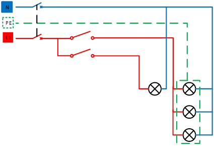
The connection of two groups of lamps is controlled at one point, and each lighting circuit operates independently. Implemented by a switch in one direction with two independent keys and contacts. This connection is usually used in chandeliers.
General schemes
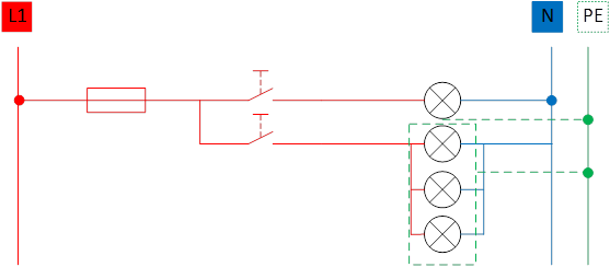
Single line lighting control diagram
Analytical chart
All lighting circuit diagrams are usually drawn in the off state, unless there is a good reason to show the switch on.
Operating diagram of lighting control
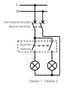
Two-position lighting control scheme (scheme from two posts)
Description
Turning the lighting circuit on and off can be done from two points (A and B). This type of lighting control scheme is mainly used in long corridors, rooms with two entrances, bedrooms, stairs, etc.
General lighting control schemes
Single line lighting control diagram
Analytical lighting control scheme
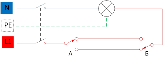
Operating diagram of lighting control
 This the lighting circuit diagram can be implemented using a two-way switch with two independent keys and contacts. In this case, you can control two groups of lamps from one point.
Switching the lighting circuit with two extreme switches and one or more intermediate switches.
Description:
 Control of a lighting circuit from three or more points. This type of circuit is used in large rooms, long corridors, stairs and usually in large rooms. Lighting control from three places is implemented using two switches in two directions, and one switch in one direction.
General schemes
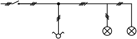
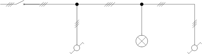
Single line diagram
![]()
Analytical lighting control scheme
Operating diagram of lighting control
When managing from multiple locations, more than three, alternative lighting circuit diagram can be formed using impulse relay pushbuttons. The impulse from the button turns on the relay TL. In this scheme, you can place a dimmer. In this way, you can organize the control of the circuits of the whole house. This method is implemented in residential buildings and small offices, using centralized push-button switches that control all lighting circuits. In this case, there is no need to enter all rooms and check whether the light is off, as the light is turned off by centralized switches.
Alternative lighting control solutions
infrared system
Lighting control is carried out from a variety of points, within line of sight, using a remote control, which is directed to a switch with a built-in infrared receiver. This system allows you to adjust the lighting without getting up from your seat.
radio system
In residential buildings and small offices, it is advisable to use lighting control using an RF transmitter and several RF receivers to reduce the number of wires to be laid. The control can be carried out by several lighting circuits. Ability to manage scenes or scenarios. This type of control can be attributed to smart home networks. Wide choice of receivers (mobile sockets, ceiling-mounted or flush-mounted receivers). Ability to share with IHC devices.
Scenes and scenarios
The scene adapts the lighting of a given, specific situation, makes it easier to control and makes life more comfortable.
Examples of scenes in the cottage:
“The empty house” is a scene that turns off all the lights and even reduces the heating temperature, closes the blinds, puts the house on an alarm. There is no need to go around all the rooms to turn off the lights in them.
"People came to the house" - a scene that turns on the lights in the hallway, living room and dressing room.
"Watching TV" - a scene that turns off or dims the lighting in the viewing area.
"I'm Having Dinner" is a scene that creates a cozy atmosphere by dimming some of the lighting.
Scenes are being used more and more in home management. Can be created using radio system and IHC, KNX devices.
Timer
After switching on, the light stays on for the set amount of time. It is applied in utility rooms, dressing rooms, restrooms.
Time relay
Turning the lighting circuit on and off every day at the same time, which can use several time intervals that can be set to different durations depending on the time of year.
Application: lighting of car parks, shop windows.
Main advantages:
Save energy by turning on the lights at the right time.
Increasing comfort and safety (no need to search for a switch and avoid sudden blackouts by strangers).
Light level switch
Used in outdoor lighting. Turning on and off the light occurs depending on the intensity of natural light.
Systems using programmable microcontrollers
Lighting circuits are controlled by programmable controllers to which push-button or key switches and lighting devices are connected. The advantage of such systems lies in the control of not only lighting, but also sockets, heaters, ventilation, etc. In these systems, control signals are transmitted through power networks, low-voltage networks and radio channels, and all unused parts of the power network can be de-energized. This approach increases the level of electrical safety in the house. The operation of such systems is based on a different network topology. Signaling uses different protocols, which provide different probability of failures in operation and different probability of incorrect operation. There are many building automation technologies, among them are Clipsal Bus (C-Bus), Lexel Intelligent Home Control (Lexel IHC), European Installation Bus EIB or KNX and many others.
The article presents lighting control schemes using pass-through and cross switches, bistable relays, dimmers, dimmers, photo relays, timers and infrared motion sensors.
Lighting control schemes have already been repeatedly considered in the literature and on the pages of various Internet sites of electrical engineering. Therefore, here we will try to in general terms cover various existing solutions.
The simplest control schemes for a one- or two-gang switch are known to everyone and, therefore, of little interest to anyone, so let's move on to the consideration lighting control schemes from multiple locations.
Let's start with a specific simple situation - let's say you have a country house two floors. In the evening you go up the stairs to the second floor. Naturally, you need to turn on the light on the stairs. We turn on the first floor. We rise to the second floor. Now the light on the stairs needs to be turned off.
But how to do this if the switch is installed on the first floor? Naturally, the obvious answer suggests itself - the lamps must be controlled from two places - from the first and second floors.
At first glance, nothing complicated - just install on each floor a switch, which are connected in parallel and control them independently of each other. But such a scheme will not work according to the algorithm we need - with its help you can turn on the light from any of the two switches, but turn it off - only from the one from which the switch was made - because. one switch in the on state will block the operation of the other. Therefore, for the considered situation with the stairs, this scheme is absolutely unacceptable.
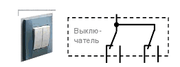
To implement lighting control from two places, you need special switches, which are called pass-through. In general, in this situation, the term "switch" is incorrect. This is a "switch", because it has three contacts - one movable and two fixed. Depending on the position of the switch key, the moving contact closes either with one or the other fixed contact. But in order not to get confused in terms, we will call this switch a pass-through switch.
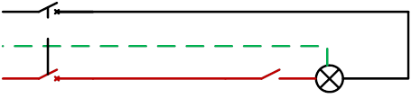
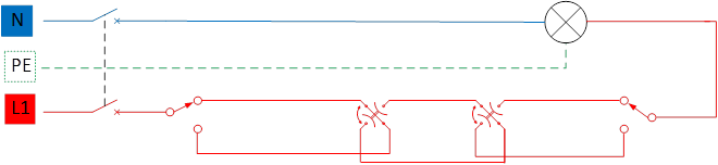
By turning on two such switches according to the diagram shown in Figure 1, we will be able to control one lamp (or several at the same time, if they are connected in parallel) from two points independently of each other. The moving (changeover) contacts in this diagram are the contacts highlighted in blue.
Fig.1. Control of one lamp from two points.
A feature of pass-through switches is that they do not have a strict key position. If in a conventional switch, as a rule, the on position is pressing up, and turning off down, then in the pass-through switch, the on-off position will depend on the position of the second switch. If, for example, you turn on the light from the first switch by “clicking” it up, and turn it off from the second, then the next time you turn on the light with the first switch, you must “click” it down.
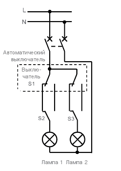
In addition to single ones, there are double ones. They allow you to control two independent lamps from two places. These are actually two single walk-through switches in one housing. The connection diagram of such switches is shown in Figure 2.
Fig.2. Control of two lamps from two points.
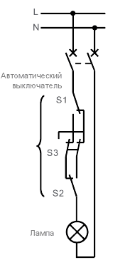
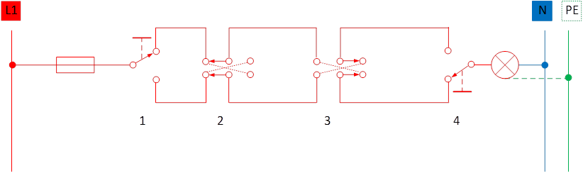
But sometimes the situation requires control not from two, but from three or more places. Here already some pass-through switches are not enough. The circuit must be supplemented with four-contact switches - the so-called cross switches.
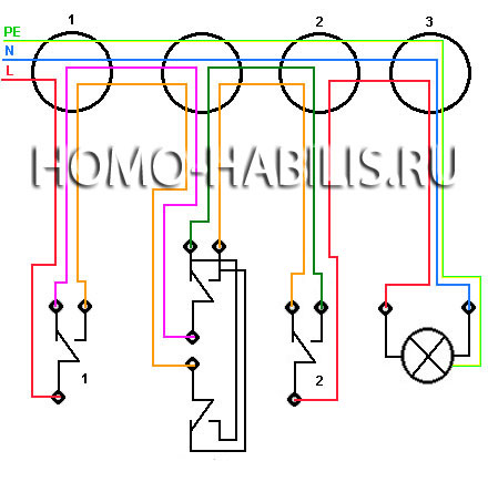
The cross switch has four contacts and is more complex than the pass switch. It is installed "in the middle" of the circuit - i.e. the first and last switches in the lighting circuit will be through, and all cross switches must be installed at all "intermediate" points. As an example, Figure 3 shows a three-point luminaire control circuit.
Fig.3. Light control from three points.
The control scheme using walk-through and cross switches is not the best solution when you need to control lighting from three or more places. Such a control scheme is much easier to organize using bi-stable, or as they are called in another way, bistable relays.
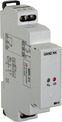
This relay is electronic circuit trigger - a device with two stable states and is controlled by a short pulse applied to its input. This allows the use of non-latching switches (buttons) for lighting control. All buttons are connected in parallel to each other, which greatly simplifies the circuit and, accordingly, the installation of lighting. Typically, such a relay is a standard 17.5 mm module mounted on a DIN rail and mounted in a switch cabinet (Figure 4)
Fig.4. Appearance bi-stable relay.
The two-state relay shown as an example, depending on the modification, may have one normally open contact, two normally open contacts, or a normally open and normally closed contact. Such relays can operate both in a 230V network and at a voltage of 24V. The circuits for switching on a two-state relay are shown in Figure 5.
Fig.5. Schemes for switching on a two-stable relay.
To implement a lighting control circuit on a two-stable relay, it is most convenient to use its normally open contact. In both diagrams, such a contact is a contact with outputs 1-2. The number of control buttons can be any, and all of them are connected in parallel.
The first press of any button will apply a control voltage level to input A1, which will turn on the relay, close the contact and, accordingly, turn on the lighting, the second press will turn it off, and so on in a circle.
The advantage of this circuit from the above circuit on the pass-through switches is the absence of the need to use cross switches and a much simpler installation of the lighting system. The disadvantage is the use of a special two-stable relay. But in the presence of such a relay, this scheme is the most optimal both in terms of installation and subsequent troubleshooting.
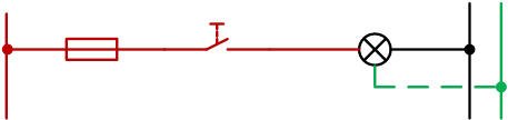
Separately, it is necessary to dwell on such devices as dimmers (dimmers). They allow you to control the brightness of the lamp. There are regulators for various types luminaires - with incandescent lamps, fluorescent lamps, halogen lamps, etc. For example, let's look at the appearance and switching on of a remotely controlled from different points (Figure 6).
As can be seen from the diagram, the switching on of the control buttons in this dimmer is carried out similarly to the control scheme using a two-state relay - they are all connected in parallel and there can be any number of them. To ensure protection, the dimmer is switched on via circuit breaker. The total power of the lamps can be 600 watts. Wiring diagram for fluorescent lamps similar, the only difference is that a different type of regulator is used.
Fig.6. Scheme for switching on a remotely controlled dimmer.
This type of dimmer is mounted in a distribution cabinet on a DIN rail. However, in most cases, dimmers are used in everyday life, which are installed instead of existing circuit breakers. They have landing dimensions, like a standard switch. The appearance of the dimmer is shown in Figure 7.
Adjustment is carried out by rotating the potentiometer knob - when rotated clockwise, the brightness of the lamp increases, counterclockwise - decreases. Sometimes control is done using buttons. The power control element in the dimmer circuit is.
Fig.7. Dimmer.
When replacing conventional switches with dimmers, one very important nuance should not be forgotten - there are dimmers that are included in the power supply of the lamp, and some require a constant supply of 230V power.
In the first case, there are no questions about replacement - the dimmer simply turns on instead of the switch. In the second case, it is necessary to bring an additional neutral wire into the landing box - to ensure full power supply of 230V. Therefore, if the electrical wiring is not reconstructed, then the first method is clearly preferable. The switching circuits for various types of dimmers are shown in Figure 8.
Fig.8. Inclusion of various types of dimmers.
The methods of lighting control considered above, with all their convenience, have one moment, and maybe for someone a drawback - to turn the lighting on or off, you need to go to the switch. Do not be tied to the switch and adjust the brightness at the same time allow electronic remote switches. They come in both with infrared (IR) control, where a remote control from any household appliances as well as radio control.
As an example of an IR-controlled switch, one can name the well-known Sapphire switch (Figure 9). It allows you to turn on / off the light, and smoothly adjust the brightness of the lamp. With all its advantages, as a disadvantage, it should be noted that this switch can be controlled only within the line of sight, as long as the "range" of the control panel is enough - usually no more than eight meters.
Fig.9. Appearance of the Sapphire switch.
Switches operating over a radio channel do not have such a drawback as control only within the line of sight. The radio signal can also pass through various obstacles - walls, ceilings, etc. To a certain extent, of course. In such switches, as a rule, a frequency of 433 or 492 MHz is used, which does not require permission from the radio surveillance authorities. The output power of transmitters for such devices is not more than 10mW.
Remotely controlled switches (both via IR and radio) can be either single-channel (allowing you to control only one load) or multi-channel. Multi-channel switches are convenient in that they can be placed, for example, in a switch cabinet and bring control objects to one point. Single-channel switches are usually placed in junction boxes of the lighting line.
An example of the implementation of a single-channel radio switch mounted in junction box, shown in Figure 10. Without fail, both in single-channel and multi-channel switches, local (manual) control is provided in case of failure of the control panel.
Fig.10. Single channel radio switch.
Radio-controlled switches, although they have a much greater range than switches built on infrared rays, however, it is also limited - as a rule, no more than 100 meters (although there are different options).
But what to do if you need to turn on the lighting or any other load, being tens and hundreds of kilometers away from the controlled object? And this is not such a useless function - for example, remote switching on of lighting in a country house will create the effect of the presence of the owners, in winter time turn on underfloor heating so that it would be warm in the house by your arrival, turn on the air conditioner in summer, etc.
This is where systems controlled remotely via cellular lines or via the Internet come to the rescue. Such devices are now quite widely represented on the market. The author of this article at one time also independently developed a four-channel "switch" for GSM. Its appearance is shown in Figure 11.
Fig.11. Four-channel control and monitoring device.
This device, called the multifunction control and monitoring device, has a built-in GSM module. To use it, it is enough to connect the required loads to the output channels and insert an activated SIM card.
Access to management is as follows - dialing to the number of the installed SIM card is made, after the programmed number of calls, the device is connected to the line and it is necessary to enter the set password from the phone keypad. If the password is incorrect, the device is disconnected from the line, if it is correct, any of the four loads can be controlled (turned on or off).
This project is non-commercial, all documentation about it, including the one, is freely available and anyone with some knowledge in the field of electronics can make it on their own. You can get acquainted with this device in more detail, as well as download all the documentation on it, on the author's website - http://electromost.com - Control and monitoring device.
All the above control schemes have one common feature - they are controlled by a person's command, in other words, an operator. But there is a whole class of devices that can work without direct human intervention. These include control relays by a command from a light sensor, a motion sensor, and according to a previously established time algorithm.
Relay with light sensors (photo relay) often used to control street lighting- When darkness falls, they turn on outdoor lighting fixtures. The threshold for such relays can be adjusted depending on the level of illumination. The appearance together with the sensor is shown in Figure 12. It contains one control contact, which allows you to control the luminaire directly from the relay, or, at high loads, through an additional one.
Fig.12. Photocell with sensor.
Relays that control the load according to a given time algorithm are called programmable timers. They prescribe the required time to turn on and off the load. Sometimes timers are integrated with a photo relay.
What is it for? Suppose we need to turn on outdoor lighting after dark, then turn it off from one in the morning, turn it on again at four in the morning and turn it off in the morning when it becomes light. To do this, the photo relay and the timer are assembled in a serial circuit. At the onset of darkness, the photorelay will turn on the lamp, but at one in the morning the timer will break the circuit and the lamp will go out. Then at four in the morning the timer will reassemble the circuit - the lamp will turn on. And finally, when it becomes light, the lamp will turn off the photo relay.
Depending on the modification of the timer, events can be programmed in it from a day to one year. A variety of such timers are astronomical relays. As a rule, these relays are also used to control outdoor lighting - geographic coordinates of the area are entered into it as an input value, and the device, based on this information, calculates when it is necessary to turn the lighting on or off. The appearance of some types of timers is shown in Figure 13.
Fig.13. Appearance of some types of programmable timers.
And in conclusion, let's focus on lighting control with the help of . Similar sensors are used in security systems to detect the presence of a person in a protected area. Only there the sensors are designed so that when they are triggered, the security system sends an alarm signal to the private security console.
In our case, the triggering of the sensor should turn on the lighting on certain time. If after this time there is no activity (movement) in the controlled area, the lighting is turned off. Otherwise, the lighting remains on for the same time interval.
The use of lamps controlled by motion sensors is very convenient in places common use- in stairwells and corridors apartment buildings. These lamps are also great for outdoor lighting, for example, in the courtyard of the house. They allow not only convenient control of lighting, but also save energy, which is quite important in our time. The appearance of the luminaire with an integrated IR sensor is shown in Figure 14.
Fig.14. The appearance of the lamp with an IR sensor.
Of course, within the framework of one small article it is impossible to cover all existing modern ways of lighting control. In it, I tried to consider the most traditional and frequently used.
The task of controlling lighting from two or more places is often encountered in everyday life. So you can organize lighting in the entrance, a long corridor or a room with several exits. It is convenient and helps to save energy. What does it take to turn the light on and off with several switches?
The lighting control scheme from two places is very simple. It includes two walk-through switch and widely distributed on the Internet.
Just mount such a system by circuit diagram quite difficult. more convenient wiring diagram for lighting control from two places shown in the figure.
All connections are made in three junction boxes - a box for each switch and a box for the lamp.
A three-wire cable from the input shield (L-N-PE) and a three-wire cable from the first pass-through switch are inserted into the first box. A four-wire cable is laid between the first and second junction boxes.
A four-wire cable from the first box is inserted into the second box, a three-wire cable from the second pass-through switch. A three-wire cable is laid between the second and third boxes.
A three-wire cable from the second box and a three-wire cable going to the lamp are inserted into the third box.
For incandescent lamps of normal power, and even more so for energy saving lamps enough cross-section of wires in the cable 1.5 sq. mm. Of course, you can be a little greedy and do without protective conductor PE, then there will be one less wire in each cable between the boxes. But this contradicts the PUE, and indeed you should not joke with electricity.
The wire connections in the junction boxes are clear from the figure. Be careful - a typical mistake is to install a chain of switches into a gap not in the phase, but in the neutral conductor. This is very dangerous, since the switched off lamp will still be under the full voltage of the 220V network!
Therefore, even if the lamp is at the beginning of the chain of switches, the phase must still be brought to the far passage switch and switching must be started from it. So, by the way, less wires are needed. Here is the wiring diagram.
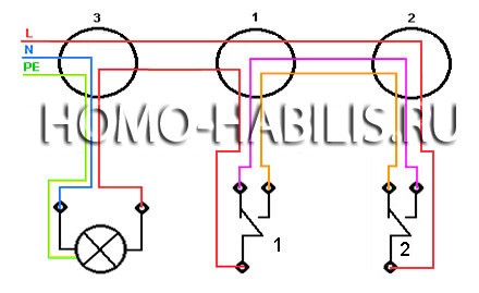
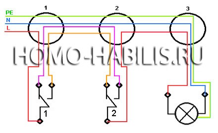
Well, what if you need to control the lighting not from two, but from three or more places? And there is a way out - circuit with a cross switch!
For some reason, there is an opinion that connecting a cross switch requires some special knowledge. And even experienced electricians are reluctant to take on such work. But look at the wiring diagram.
Compared with the first scheme, nothing exceptionally complicated appeared. Another junction box included in the gap between junction boxes 1 and 2. A four-wire cable from the cross switch is inserted into the same box. The connections in the cross switch, shown in the diagram as black wires, are already made inside the switch, so it is connected with four terminals. The wiring diagram of the contacts inside the switch and the terminal designations are indicated in the instructions, on the box or on the back of the switch itself.
Usually, incoming wires are connected to the cross switch from below, and outgoing from above. But if you do the opposite, nothing bad will happen. And even if you connect one incoming one from above, and the second one from below, and in the same way separate the outgoing wires - again, short circuit will not happen. Just in one of the positions of the cross switch, turning on the lamp at any position of the other switches will not work. This will be a sign that the wires on the cross switch are reversed.
By the same principle, in the gap between junction boxes 1 and 2, you can include as many cross switches as you want. And this means lighting control from three, four, five, six or more places - as much as your heart desires. Isn't it all simple?
Of course, if more than three switches are required, and even more than four, then it is more correct and cost-effective to use a bistable relay. But this is a topic for a separate discussion.
But interesting video. The peculiarity here is that instead of a cross switch, double pass.
We advise you to read
, diagnosis, treatment Treatment of urogenital chlamydia") Chlamydia urogenital - description, causes, symptoms (signs), diagnosis, treatment Treatment of urogenital chlamydia
Chlamydia urogenital - description, causes, symptoms (signs), diagnosis, treatment Treatment of urogenital chlamydia The benefits and significance of hydroamino acid threonine for the human body L threonine what
 To wait or not to wait for a guy from the army For what reason can they be commissioned from the army
 Baked apples with cottage cheese Baked apples with cottage cheese

