System classification automatic regulation
Automatic control systems used in modern technology, are quite varied. Rapid Expansion functional purpose functional purpose of automatic systems, which became possible, in particular, due to the introduction of computer technology, increases the number of realized classes of systems. Under these conditions, it is almost impossible to give a complete detailed classification of automatic control systems. Classifications that have been successfully applied in the recent past are now becoming too narrow, not covering new systems being developed and implemented.
Any classification is based on certain classification features. From the point of view of the generality of the classification of automatic control systems, the most convenient classification feature is the information used about the object of regulation. It should be noted that almost all automatic systems are non-linear devices that contain both variables and distributed parameters, in which the value of variables at a given time may depend not only on the current, but also on the past values of these variables.
Each automatic system is characterized by a functioning algorithm - a set of prescriptions that determine the nature of the change in the controlled variable depending on the impact
Depending on the nature of the change in the components of the driving influence, automatic systems are divided into four classes:
- automatic stabilization systems, in which the master action is constant value, and the controlled value is automatically maintained unchanged with an arbitrary change in the load and external conditions. The load of the regulated object (load torque on the motor shaft, generator load) in stabilizing systems is usually the main disturbing effect that most sharply affects the controlled value;
- systems of programmed regulation, in which the driving force and the regulated value change according to a predetermined law. A software automatic system can be considered as a stabilization system, in which the stabilization task is complicated by the task of changing the controlled variable according to a given program. Changing the controlled value according to the program is achieved by adding to the system some element of a software device that changes the setting action in time according to a predetermined law;
- servo systems involve changing the controlled variable in accordance with the change in the driving force, the law of change of which is an unknown function. Thus, the servo system, like the software system, reproduces the master action. However, this effect in the tracking system does not change according to a predetermined program, but arbitrarily. For example, the radar antenna turns to follow the aircraft, the trajectory of which is not known in advance, i.e., “follows” it. This is where the name tracking system comes from. The master influences and controlled values of servo systems can have a diverse character in their physical nature. Moreover, the controlled value by its physical nature may differ from the setting action.
-
optimal control systems provide optimal maintenance of the regulated value according to one or another optimality criterion
Depending on what mathematical model describes the processes in automatic systems, they are divided into:
- linear automatic systems, the mathematical model of which is composed of linear or linearized differential equations. If in the equation of dynamics of any link of a linear automatic system there is at least one or several time-variable coefficients, then a linear automatic system with variable parameters is obtained. If any link is described by linear partial differential equations, then the automatic system will be a linear automatic system with distributed parameters. In contrast, an ordinary linear automatic system is a lumped-parameter automatic system. If the dynamics of any link in the automatic system is described linear equation with a delayed argument, then the automatic system is called a linear automatic system with a delay;
- non-linear automatic systems, the mathematical model of which is composed of non-linear differential equations. Nonlinear automatic systems include all automatic systems, in the links of which there are static characteristics of any of the many types of nonlinearity. Non-linear can be automatic systems with variable parameters, with distributed parameters, with delay, impulse and digital automatic systems, if the linearity of the dynamics equation is violated somewhere in them.
Classification of automatic control systems
Each automatic system consists of a number of links, interconnected in an appropriate way. Each individual link has an input and output that determine the impact and transfer of information from one link to another. AT general case any link can have several inputs and outputs. The input and output quantities can be of any physical nature.
During the operation of the automatic system, the input and output values change over time. The dynamics of the signal conversion process in this link is described by some equation that relates the output variable to the input variable. The set of equations and characteristics of all links describes the dynamics of control or regulation processes in the entire system as a whole.
The main features of the division of automatic systems into large classes according to the nature of internal dynamic processes are the following:
- continuity or discreteness of dynamic processes in time;
- linearity or non-linearity of the equations describing the dynamics of control processes.
Depending on the nature of the change in control signals, automatic systems are divided into three classes:
- continuous (analogue) systems, which are described by ordinary differential equations and in the process of regulation the structure of all connections in the system remains unchanged. Signals at the output of individual links of such a system are continuous functions of influences and time. There is a continuous functional connection between the links at the input and output of the automatic system. In this case, the law of change in the output value in time can be arbitrary, depending on the form of change in the input value and on the form of the link dynamics equation. In order for the automatic system as a whole to be continuous, it is necessary, first of all, that the static characteristics of all links be continuous;
- discrete (digital) systems, which are described by differential-difference equations and in them, at discrete time intervals, the control action circuit is opened or closed. In discrete systems, the opening of the action circuit is carried out forcibly and periodically by special interrupting devices. Such systems contain impulse elements and perform signal quantization both in terms of level and time. A link that converts a continuous input signal into a sequence of pulses is called a pulse link. If the subsequent link of the automatic system is also discrete, then for it not only the output, but also the input value will be discrete. Discrete automatic systems include automatic systems of impulse control, as well as automatic systems for control computers. These latter give the result of the calculation at the output discretely, at certain intervals, in the form of numbers for individual discrete numerical values of the output quantity;
- relay (discrete-continuous) systems, which are described by both types of equations. In these systems, the opening or closing of the action circuit is carried out by one of the links of the system with a continuous value of the input action. Opening or closing is carried out using a relay or a link with a relay characteristic. The relay is triggered at certain values of influences on its sensitive organ. Relay systems carry out quantization of signals in time. The static characteristic of the relay link has break points.
Each of these three classes of automatic systems is divided into subclasses:
- stationary automatic systems with lumped or distributed parameters;
- non-stationary automatic systems with lumped or distributed parameters.
In the study, calculation and synthesis of automatic systems, it must be borne in mind that the theory and various applied methods for ordinary linear automatic systems have been most fully developed. Therefore, in the interests of simplicity of calculation, it is always desirable to reduce the problem to such a form as to make maximum use of the methods of studying ordinary linear automatic systems. Usually, the equations of dynamics of all links of an automatic system are tried to be reduced to ordinary linear ones, and only for some links, where this is unacceptable or where a special linear or non-linear link is specially introduced, these special properties are taken into account.
However, this does not mean at all that when designing new automatic systems, one should strive for ordinary linear automatic systems. On the contrary, it is quite obvious that ordinary linear automatic systems have limited capabilities. The introduction of special linear and non-linear links can give the automatic system best qualities. Automatic systems with specially introduced nonlinearities and discrete automatic systems, including those with control computers and microprocessor-based automatic systems, have especially rich possibilities.
According to the type and number of signals, automatic control systems are divided into:
- single-circuit systems in which there is one adjustable value;
- multi-circuit systems in which there are several main or local feedbacks;
- systems of incoherent regulation are intended for regulation of various quantities, are not connected with each other and can only interact through a common object of regulation.
a) in dependent systems of incoherent control, a change in one of the controlled variables affects the change in others. Therefore, in such systems, regulatory processes cannot be considered in isolation from each other;
b) in independent systems of incoherent control, the change in one of the controlled values does not depend on the change in the others;
- systems of connected regulation assume the presence of several regulators, the regulated values of which have mutual connections with each other, carried out in addition to the object of regulation.
Depending on the presence or absence of a regulation error, ATS are divided into:
- static systems are such systems that assume the presence of a constant control error (droop). characteristic feature work static system is that the equilibrium of the system can be reached when different values regulated quantity and each value of the regulated quantity corresponds to a single value of the regulatory body;
- astatic systems are such systems that, for various values of external influence on the object, there is no deviation of the controlled value from the required value. In such systems, the equilibrium state takes place with one single value of the controlled variable equal to the given one, and the regulating body must be able to occupy different positions with the same value of the controlled variable.
Principles of automatic control
The principle of operation of any automatic control system is to detect deviations of controlled values that characterize the operation of the regulated object or the flow of the process from the required mode and, at the same time, act on the regulated object or process in such a way as to eliminate these deviations.
In the management process, there is always physical quantities that need to be changed in a strictly defined way.
Automatic control systems should, based on the measurement of regulated values, form control actions on the regulated object. Changing the behavior of the regulated object can be carried out according to the principles of open or closed cycles.
In an open automatic system the control action is formed on the basis of the value of the specified value. In such systems, there is no connection between input and output. As a result, the flow of the control process in open systems does not depend on the results, that is, on how the system performs its functions. In an open automatic system, only direct action takes place: from the operator to the regulated object, from the input to the output. The simplest example- the process of switching on electric lighting in the room.
In order for the regulated value y(t) of the regulated object to take the required value, an input action x(t) is applied to its input. However, in practice, the controlled value y(t) of the regulated object deviates from the required value for a number of reasons. One of these reasons is the influence of various kinds of external disturbing influences f(t) on the object of regulation. Another reason is the influence of changing the parameters of the regulated object or other elements of the system, i.e. the influence of parametric disturbances (gain factors, time constants, etc.). The third reason that causes deviation of the controlled variable is due to the change in the required value of the controlled variable (change in the required temperature of the hardening furnace, arbitrary change in the angular coordinates of the target). If the required value of the regulated variable changes, then for a corresponding change in its actual value, it is necessary to change the control action h(t) at the input of the regulated object. When the control action changes at the input of the control object, which has inertia, a transient process occurs, during which the controlled value will not correspond to the required value.
Deviation of the controlled value from the desired value can occur not only in transient, but also in steady dynamic mode, when the required value changes, for example, at a constant speed or constant acceleration. The deviation of the controlled value under the influence of the listed reasons can reach unacceptably large values, at which the technical process provided by the object is violated. Therefore, the problem arises of reducing the deviations of the output values of objects from the required values. This task is the main task of management (regulation).
It is obvious that the need for a control action arises in those cases when the process in the object of regulation deviates from the prescriptions given by the functioning algorithm.
The control algorithm in such automatic systems is determined by the properties of individual links or the nature of the input signals. Many automatic systems operate on the principle of open-loop control, which have a predetermined algorithm of actions. For example, starting an internal combustion engine, turning on a compressor on a locomotive, feeding sand under wheelsets, the process of charging the battery, etc. For the normal functioning of such automatic systems, a number of measures must be observed.
In this system, the control action can be generated by a person. Comparing the actual and required values of the controlled variable, a person can identify the deviation between them, and in accordance with the magnitude and sign of this deviation, the magnitude of the control action is determined.
Firstly, full correspondence between the set and actual values of the controlled variable can take place only if the characteristics of the individual links of the automatic system are stable and the influence of external disturbances is excluded.
Secondly, they must be carefully tuned, i.e., each position of the driving device must strictly correspond to the value of the controlled variable. However, saving the settings when the parts are worn or the elements age, as well as when the temperature changes environment presents a difficult task. Therefore, open-loop systems cannot provide high control accuracy. They do not measure the result caused by the control action, and do not take actions that influence this result so that it corresponds to the desired one.
In closed automatic systems, the controlled value is compared with its set value, and a control action is formed on the basis of the error signal. The progress of the automatic control process depends on the results of this comparison.
To implement such a control algorithm, a connection is introduced into the design of the automatic system, which is called feedback, because it transmits a signal from the output of the regulated object to the input of the automatic system in the direction opposite to the direction of transmission of the control action to the regulated object.
The easiest way is to plant a human operator who will play the role of feedback, for example, in the process of manual control vehicle be it a car, a tractor, a locomotive, an airplane or a spaceship. In this case, comparing the readings control devices, measuring the actual value of the controlled variable (speed, power, thrust, flight altitude, etc.), with its given value, the human operator makes an additional impact on the controlled object in order to achieve the minimum deviation of the controlled variable from the set value.
|

On the one hand, the actions of a human operator are elementary simple, and on the other hand, monitoring a multitude of devices is quite tedious, and can easily be performed by a special automatic device that compares the setpoint and actual value of the controlled variable and, on its basis, forms a control action on the regulated object. Thus, the first automatic regulators appeared, designed to replace the monotonous and inefficient labor of a person with automatic device. Such a device is automatic regulator.
The object of regulation and the automatic regulator form a closed system.
In closed automatic systems, the actions of a human operator are reduced to the initial setting of a given mode and general monitoring of the processes in the automatic system. The accuracy of regulation in closed automatic systems, i.e., the accuracy of maintaining the required functional relationship between input and output, mainly depends on the accuracy with which the required and actual value of the controlled variable is compared.
Closed-loop automatic control systems differ in the principle of regulation:
- by deviation;
- out of indignation;
- combined.
Automatic control systems based on the deviation principle, are the main ones in the practice of automation of various production facilities. They are characterized by the presence of feedback, which supplies part of the output signal to the input of the automatic system and forms a closed control loop. The essence of this control principle is that the actual value of the controlled variable is constantly compared with its value. h given value. If there is a difference between these values above a predetermined threshold, the system develops a regulatory action aimed at eliminating this difference or at reducing it to a certain acceptable value.
|
The required value of the regulated value of the automatic system y(t) is determined by the driving force x(t) coming from the driving device. The deviation of the controlled value y(t) from the set value can be caused both by the influence of various kinds of disturbing influences, and by a change in the setting action x(t). To reduce or eliminate this deviation, it is necessary to develop an appropriate control action h(t) and apply it to the input of the control object. The control action when using the deviation control principle is generated as a result of converting the deviation Dx(t) of the controlled variable from the set value.
In automatic systems operating on the principle of deviation, the control action h(t) is obtained as a result of the transformation of the deviation signal, and not the factor itself that caused the deviation, for example, the disturbing action f(t) (i.e., as a result of the transformation of the consequence, and not the cause itself), so it cannot have a reverse effect on the object without delay compared to the perturbing effect. Consequently, the principle of deviation control does not make it possible to completely eliminate the deviation, i.e., achieve absolute invariance.
In automatic systems operating on the principle of deviation, the control action is obtained as a result of the transformation of the deviation, which can be caused by various factors. Therefore, in these systems, the deviation decreases, regardless of which of the factors it is caused by. Since in automatic systems operating on the principle of deviation, the deviations that occur when the parameters of the elements of the automatic system change also decrease, then closed automatic systems will be less sensitive to changes in the parameters of its elements compared to open automatic systems, where deviations caused by changes in the parameters of their elements, are not compensated.
Automatic systems operating according to this principle have a high accuracy of maintaining the controlled value (due to the presence of constant control of the difference between the set and actual values), but low speed.
The low performance of such systems is due to the fact that
1. The closed loop of automatic control, created by the automatic controller and feedback, includes the object of regulation. In practice, the object of regulation is almost always the most inertial link in the automatic system;
2. They do not react to the cause that causes the mismatch between the setpoint and the actual value of the controlled variable, but to the consequence - the mismatch between the setpoint and the actual value of the controlled variable.
To build an automatic control system operating on the principle of deviation, other things being equal, a minimum amount of initial information about the object of regulation is required. Almost all information about the object of regulation is transmitted via feedback. The presence of feedback is characterized by the fact that the application of some influence to the automatic system entails a counteraction that restores the state of the entire automatic system.
In the simplest case, the automatic controller compares the output signal of the automatic system with the reference signal to find out how correctly the automatic system performs its task. The presence of feedback in an automatic system changes its static and dynamic characteristics. Thanks to feedback, an automatic system can be more accurate and faster, or vice versa, slower. It can make the automatic system stable or unstable.
Systems operating on the principle of deviation have the following advantages:
1) reduce the deviation of the controlled variable from the required value, regardless of what factors (external disturbing influences, changes in the parameters of the system elements, changes in the setting action) caused it;
2) are less sensitive to changes in the parameters of the system elements, compared with open systems.
Systems operating on the principle of deviation have the following disadvantages:
1) in simple single-loop systems with the principle of control by deviation, absolute invariance cannot be achieved;
2) in systems with the principle of regulation by deviation, as in closed systems, the problem of stability arises.
Due to the significant advantages of the system with the principle of regulation by deviation, they are widely used in technology.
Automatic control systems operating on the principle of disturbance compensation, are designed to reduce the influence of disturbing influences on the regulated object by measuring these influences and compensating for their influence due to the reverse artificial impact on the regulated object.
When developing this principle, engineers proceeded from the assumption that in order to reduce or eliminate the deviation of the controlled value from the set value caused by the influence of one or another factor, it is necessary that the control action be a certain function of this factor and the characteristics of the regulated object.
When regulating according to the principle of disturbance compensation, the problem is to compensate for the influence of the disturbance on the controlled value.
The working information in these systems are disturbing influences, bad influence which are subject to compensation. Therefore, in these systems, it is possible to fully compensate for the influence of the perturbing action on the controlled variable, i.e., it is possible to achieve invariance (independence) of the controlled quantity with respect to this perturbing action. The considered method can compensate for the influence of each of the disturbing influences separately. However, in practice, it is usually not possible to compensate for the influence of all disturbing influences, since a significant part of the influences cannot be measured, and when trying to compensate for all possible disturbing influences, an extremely complex system is obtained.
Such automatic systems require initial information even more complete than automatic systems operating on the principle of deviation. Indeed, in order to compensate for the influence of any perturbation in steady state, and even more so in transient conditions, it is necessary to know exactly this influence.
In this case, one (main) or two (no more) perturbations are selected and it is determined how they affect the controlled variable. The control action applied to the object of regulation by the executive body depends on the disturbance so that the changes in the controlled value do not go beyond the specified limits. Such systems are simple and stable in operation, but they are not able to respond to other perturbations that cause a deviation of the controlled variable.
|

The principle of perturbation compensation is that in order to reduce or eliminate the deviation Dx(t) of the controlled variable from the set value caused by the perturbing action f(t), this effect is measured and, as a result of its transformation, the control action h(t) is generated, which, when applied to the input of the regulated object, causes a compensating deviation of the controlled value y(t) of the opposite sign compared to the deviation caused by the disturbing influence f(t). The disturbance f(t) is measured using a disturbance compensator. Some automatic systems explicitly include actuators and controls.
The signal on the disturbance хв(t) in the adder is added (subtracted) with the master action, which determines the required value of the controlled variable. The total effect Dx(t) with the help of an automatic controller (for this control principle, in most cases, the automatic controller is a power amplifier) is amplified to the value necessary to obtain the required operating mode of the regulated object. The control action h(t) formed in this way enters the input of the regulated object and compensates for the influence of the disturbing action.
An automatic system operating on the principle of disturbance compensation is an open-loop automatic system. In it, the regulation process does not depend on the results of the operation of the automatic system (the controlled value is not measured and no action is taken if it does not correspond to the required value) and only a direct effect is observed.
An automatic system operating according to this principle has a high speed, but low accuracy in maintaining the controlled value. High speed is ensured by the fact that the automatic controller reacts not to the effect of the influence of the disturbing influence (deviation of the controlled variable), but to the cause - the change in the disturbing action, preparing the control object in advance for a possible deviation of the controlled variable.
Automatic systems operating on the principle of disturbance compensation have the following advantages:
1) allow you to fully compensate for the main disturbing influences, i.e. in these systems it is possible to achieve the invariance of the controlled variable with respect to disturbing influences;
2) in them, as in any open systems, there is no problem of stability.
Automatic systems operating on the principle of disturbance compensation have the following disadvantages:
1) they eliminate the influence of only the main disturbing influences, for which compensation channels are created;
2) there is a deviation of the controlled value from the required value as a result of a change in secondary disturbing influences, for which there are no compensation channels;
3) in these systems, as in open systems, deviations of the controlled value appear with a change in the characteristics of the object and elements of the automatic system;
4) the application of the disturbance control principle is limited to objects whose characteristics are known or can be determined.
Systems operating on the principle of disturbance compensation have particular applications.
Automatic control systems operating on the combined principle, combine the perturbation compensation principle and the deflection principle. Such automatic systems combine the positive aspects of the previously discussed principles of automatic control and eliminate their shortcomings.
|
In such systems, in addition to the main closed deviation control loop, the combined automatic system contains a compensation loop for one or more disturbances. The amount of working information in the combined automatic system is higher than in previous systems. Here, information about the disturbing influence is added to the operating information about the deviation of the controlled variable.
In combined automatic systems, the principle of regulation by deviation is implemented with the help of the main feedback, and the principle of control by disturbance with the help of compensation links. If the most significant error is caused by the disturbing action f(t), then a connection is introduced for this disturbance, but if such an error is obtained due to a change in the setting action x(t), then the connection for the setting action is determined by the automatic control algorithm.
In combined automatic systems, the compensation connection for the main disturbance (driving action) eliminates the component of the error caused by this disturbance (changing the driving influence), and as a result of the feedback action, the errors caused by secondary disturbing influences, for which there are no compensation connections, are reduced. If with the help of compensatory links the errors caused by the main disturbing (setting) influences are not completely eliminated, then the residual errors are also reduced with the help of feedback.
To form a control action in combined automatic systems, both direct information about the main disturbing influences (change in the master action) and the deviation of the controlled variable from the required value caused by all disturbing influences (change in the master action) are used. Thereby:
1) in combined automatic systems, with the help of compensatory links, it is possible to achieve full compensation for errors caused by the main disturbing and master influences (it is possible to achieve invariance);
2) along with the possibility of full compensation of errors caused by the main influences, in combined automatic systems, with the help of feedback, the errors caused by secondary disturbing influences, for which there are no compensation connections, as well as undercompensated errors from the main influences, are reduced;
3) if the conditions for compensating the disturbing action are violated, the resulting error is reduced by a closed automatic system, i.e., combined automatic systems are less sensitive to changes in the parameters of open channels than open automatic systems;
4) due to the presence of open compensation channels in combined automatic systems, the problem of stability is not as acute as in closed automatic systems.
Naturally, the accuracy of regulation, achievable in combined systems, is higher than the accuracy of all other automatic systems. In practice, such automatic systems are complex and expensive.
Thus, combined automatic systems are the most advanced systems with high accuracy in maintaining the controlled value. On the considered principles, not only technical systems of automatic control are built, but also control systems in society and regulatory systems in living organisms. Therefore, research methods technical systems automatic regulation to a certain extent can be used to study control systems in society and wildlife.
Introduction 5
Development of a functional diagram of an automatic control system (ACS) 6
Development of differential equations and transfer functions of system elements. 7
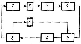
Development block diagram SAR 11
Transformation of the structural scheme of the ACS to the canonical form 12
Analysis of ACS stability by algebraic criteria 13
Calculation and construction of transient processes along the channels of regulating and disturbing influences. fifteen
Transient quality assessment 17
Graphics application 19
References 22
Introduction
In the functional design of automatic control systems, methods of the theory of automatic control are most often used. The automatic system consists of a number of technical devices with certain functional and dynamic properties. For their description and study, an automatic system is represented by a certain set of elements endowed with the corresponding properties.
Real technical objects are described by nonlinear differential and algebraic equations. But since at the initial stage of design, the tasks of preliminary evaluation of technical solutions and forecasting are solved, relatively simple mathematical models can be quite reasonably used for these purposes. In this regard, the nonlinear equations of the mathematical model are subjected to linearization.
The description of automatic systems is greatly simplified by using the methods of operational calculus. Using the Laplace transform, the linear differential equation is reduced to algebraic equation with complex variables.
Development of a functional diagram of an automatic control system (sar)
ACS can be represented by two main parts - the object of regulation and the regulatory device - the regulator.
The state of the object is determined by a number of values characterizing:
Impact on the object of regulatory devices;
Influence on the object of the external environment;
The flow of processes within the object itself.
In general, the object of regulation can be represented by the following scheme:
Rice. 1. Scheme of the object of regulation
Where Z is the totality of controlled external influences;
F - uncontrolled external influences;
X – regulatory influences;
U - adjustable values.
In our case, the object (DC generator) has one adjustable effect (forced current i c) and one adjustable value (clamp voltage U n) and is called simple or single-connected.
The behavior of the regulated object can be considered in the modes of statics and dynamics. A functional diagram is a diagram in which each functional element of the system corresponds to a certain link. The schematic diagram of the developed ATS is shown in the graphical appendix.
For this ACS, the functional diagram looks like:
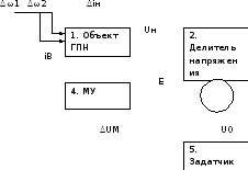
Figure 2. Functional diagram of the ACS
Where 1 - the object of regulation - a constant voltage generator;
2 – voltage divider;
3 - comparison device, is a stimulating node;
4 - amplifier (in our case, a magnetic amplifier with self-magnetization);
5 - setter - device for setting the installation.
The load current of the magnetic amplifier is a control variable, so there is no actuator on the functional diagram.
Principle of operation:
The regulated value is the voltage U n at the terminals of the generator, which is compared with the reference voltage U 0 through the divider K (U 1) mismatch E is fed to the control winding of the magnetic amplifier. The load of the magnetic amplifier is the current in the excitation winding of the auxiliary generator exciter.
The setting is given by the adjustable voltage divider ratio R 1 , which establishes the correspondence between the regulated voltage U n and the reference voltage U 0 .
Disturbing, uncontrolled influences are: voltage drop in the generator windings caused by the load current i n; interference caused by the load current i n; interference caused by a change in the speed of rotation of the generator shafts ω 1 and ω 2 ; supply voltage fluctuation of the magnetic amplifier ∆U n.
In accordance with the task on our functional diagram, the input and output values \u200b\u200bare indicated for each functional block. The actions of disturbing influences are also shown.
According to the principle of regulation automatic control systems are divided into four classes.
1. Automatic stabilization system - a system in which the controller maintains a constant set value of the controlled parameter.
2. Program control system - a system that provides a change in the controlled parameter according to a predetermined law (in time).
3. Tracking system - a system that provides a change in the controlled parameter depending on some other value.
4. Extreme control system - a system in which the controller maintains the value of the controlled variable that is optimal for changing conditions.
For regulation temperature regime electric heating installations, mainly systems of the first two classes are used.
Automatic temperature control systems can be divided into two groups according to the type of action: intermittent and continuous regulation.
Automatic regulators for functional features are divided into five types: positional (relay), proportional (static), integral (astatic), isodromic (proportional-integral), isodromic with advance and with first derivative.
Positional regulators are referred to as intermittent ACS, and other types of regulators are referred to as continuous ACS. Below are the main features of positional, proportional, integral and isodromic controllers, which are most used in automatic temperature control systems.
(Fig. 1) consists of a control object 1, a temperature sensor 2, a programming device or a temperature level adjuster 4, a controller 5 and an actuator 8. In many cases, a primary amplifier 3 is placed between the sensor and the programming device, and between the controller and executive device- secondary amplifier 6. Additional sensor 7 is used in isodromic control systems.
Rice. 1. Functional diagram of automatic temperature control
Positional (relay) temperature controllers
Positional regulators are those in which the regulatory body can occupy two or three specific positions. In electric heating installations, two- and three-position regulators are used. They are simple and reliable in operation.
On fig. 2 shown circuit diagram two-position regulation of air temperature.
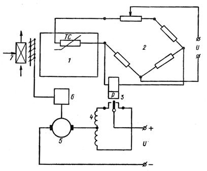
Rice. 2. Schematic diagram of on-off air temperature control: 1 - control object, 2 - measuring bridge, 3 - polarized relay, 4 - motor excitation windings, 5 - motor armature, 6 - reducer, 7 - calorific.
To control the temperature in the regulated object, the thermal resistance TS is used, which is included in one of the arms of the measuring bridge 2. The values of the bridge resistance are selected so that at a given temperature the bridge is balanced, that is, the voltage in the diagonal of the bridge is zero. When the temperature rises, the polarized relay 3, included in the diagonal of the measuring bridge, turns on one of the windings 4 of the electric motor direct current, which, with the help of reducer 6, closes air valve in front of the heater 7. When the temperature drops, the air valve opens completely.
With two-position temperature control, the amount of heat supplied can be set only at two levels - maximum and minimum. The maximum amount of heat must be more than necessary to maintain the desired controlled temperature, and the minimum must be less. In this case, the air temperature fluctuates around the set value, that is, the so-called self-oscillatory mode(Fig. 3, a).
The lines corresponding to temperatures τ n and τ in define the lower and upper boundaries of the dead zone. When the temperature of the regulated object, decreasing, reaches the value τ n, the amount of heat supplied instantly increases and the temperature of the object begins to increase. Having reached the value τ in, the regulator reduces the heat supply, and the temperature drops.
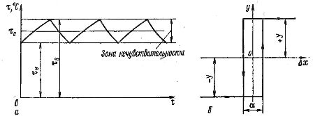
Rice. 3. Time response of on-off control (a) and static response of on-off controller (b).
The rate of temperature increase and decrease depends on the properties of the regulated object and on its time characteristic (acceleration curve). Temperature fluctuations do not go beyond the dead zone if changes in heat supply immediately cause temperature changes, that is, if there is no delay of the controlled object.
With a decrease in the dead zone, the amplitude of temperature fluctuations decreases down to zero at τ n = τ c. However, this requires that the heat supply be varied at an infinitely high frequency, which is extremely difficult to implement in practice. In all real objects of regulation there is a delay. The process of regulation in them proceeds approximately as follows.
When the temperature of the regulated object drops to the value τ n, the heat supply instantly changes, however, due to the delay, the temperature continues to decrease for some time. Then it rises to the value τ at which the heat supply instantly decreases. The temperature continues to rise for some time, then, due to the reduced heat supply, the temperature drops, and the process is repeated again.
On fig. 3, b is shown static characteristic of on/off controller. It follows from it that the regulatory impact on the object can take only two values: maximum and minimum. In the considered example, the maximum corresponds to the position at which the air valve (see Fig. 2) is fully open, the minimum - when the valve is closed.
The sign of the control action is determined by the sign of the deviation of the regulated value (temperature) from its set value. The magnitude of the control action is constant. All on-off controllers have a hysteresis zone α, which occurs due to the difference in the operating and releasing currents of the electromagnetic relay.
Example of using on/off temperature control:
Proportional (static) temperature controllers
In cases where high control accuracy is required or when a self-oscillating process is unacceptable, apply controllers with continuous control process. These include proportional regulators (P-regulators) suitable for controlling a wide variety of technological processes.
In cases where high control accuracy is required or when a self-oscillating process is unacceptable, regulators with a continuous control process are used. These include proportional regulators (P-regulators), suitable for regulating a wide variety of technological processes.
In automatic control systems with P-regulators, the position of the regulatory body (y) is directly proportional to the value of the controlled parameter (x):
y=k1х,
where k1 is the proportionality factor (controller gain).
This proportionality takes place until the regulating body reaches its extreme positions (limit switches).
The speed of movement of the regulating body is directly proportional to the rate of change of the controlled parameter.
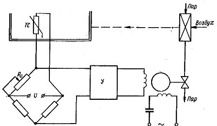
On fig. 4 shows a schematic diagram of a system for automatically controlling the room temperature using a proportional controller. The room temperature is measured by a resistance thermometer TC included in the measuring bridge circuit 1.

Rice. 4. Air temperature proportional control scheme: 1 - measuring bridge, 2 - control object, 3 - heat exchanger, 4 - capacitor motor, 5 - phase-sensitive amplifier.
At a given temperature, the bridge is balanced. When the controlled temperature deviates from the set value, an unbalance voltage appears in the bridge diagonal, the magnitude and sign of which depend on the magnitude and sign of the temperature deviation. This voltage is amplified by a phase-sensitive amplifier 5, at the output of which the winding of a two-phase capacitor motor 4 actuators.
The actuator moves the control element, changing the flow of coolant into the heat exchanger 3. Simultaneously with the movement of the control element, the resistance of one of the arms of the measuring bridge changes, as a result of which the temperature changes, at which the bridge is balanced.
Thus, due to rigid feedback, each position of the regulatory body corresponds to its own equilibrium value of the controlled temperature.
A proportional (static) controller is characterized by residual uneven regulation.
In the case of an abrupt deviation of the load from the set value (at the moment t1), the controlled parameter will come after a certain period of time (the moment t2) to a new steady value (Fig. 4). However, this is possible only with a new position of the regulatory body, that is, with a new value of the controlled parameter, which differs from the set value by δ.

Rice. 5. Time characteristics of proportional control
The disadvantage of proportional controllers is that each parameter value corresponds to only one specific position of the regulator. To maintain the set value of the parameter (temperature) when the load (heat consumption) changes, it is necessary that the regulating body take a different position corresponding to the new load value. This does not happen in a proportional controller, which results in a residual deviation of the controlled variable.
Integral (astatic regulators)
Integral (astatic) such regulators are called in which, when the parameter deviates from the set value, the regulating body moves more or less slowly and all the time in one direction (within the working stroke) until the parameter again takes the set value. The direction of stroke of the regulating body changes only when the parameter passes through the set value.
In integral regulators of electrical action, a dead zone is usually artificially created, within which a change in a parameter does not cause movement of the regulatory body.
The speed of movement of the regulating body in the integral regulator can be constant and variable. A feature of the integral controller is the absence of a proportional relationship between the established values of the controlled parameter and the position of the regulatory body.
On fig. 6 shows a schematic diagram of an automatic temperature control system using an integrated controller. In it, unlike the proportional temperature control circuit (see Fig. 4), there is no hard feedback.
Rice. 6. Scheme integral regulation air temperature
In an integral controller, the speed of the regulating body is directly proportional to the deviation of the controlled parameter.
The process of integral temperature control with an abrupt change in load (heat consumption) is shown in fig. 7 with the help of time characteristics. As can be seen from the graph, the controlled variable with integral control slowly returns to the set value.

Rice. 7. Time characteristics of integral regulation
Isodromic (proportional-integral) controllers
Isodromic regulation has the properties of both proportional and integral regulation. The speed of movement of the regulating body depends on the magnitude and speed of the deviation of the controlled parameter.
If the controlled parameter deviates from the set value, the regulation is carried out as follows. Initially, the regulating body moves depending on the magnitude of the deviation of the controlled parameter, that is, proportional regulation takes place. Then the regulating body makes an additional movement, which is necessary to eliminate the residual non-uniformity (integral regulation).
An isodromic air temperature control system (Fig. 8) can be obtained by replacing the rigid feedback in the proportional control circuit (see Fig. 5) with an elastic feedback (from the regulator to the feedback resistance slider). Electrical feedback in the isodromic system is carried out by a potentiometer and is introduced into the control system through a circuit containing resistance R and capacitance C.
During transient processes, the feedback signal, together with the parameter deviation signal, affects the subsequent elements of the system (amplifier, electric motor). When the regulating body is stationary, in whatever position it is, as the capacitor C is charged, the feedback signal decays (in the steady state it is equal to zero).
Rice. 8. Scheme of isodromic air temperature control
It is typical for isodromic control that the non-uniformity of control (relative error) decreases with increasing time, approaching zero. In this case, the feedback will not cause residual deviations of the controlled variable.
Thus, isodromic control leads to much better results than proportional or integral control (not to mention positional control). Proportional control due to the presence of rigid feedback occurs almost instantly, isodromic - slowly.
Software systems for automatic temperature control
To implement program control, it is necessary to continuously influence the setting (set point) of the controller so that the controlled value changes according to a predetermined law. For this purpose, the controller tuning unit is supplied with a software element. This device serves to establish the law of change of the given value.
During electric heating, the ACS actuator can act to turn on or off sections of the electric heating elements, thereby changing the temperature of the heated installation in accordance with a given program. Software control of air temperature and humidity is widely used in artificial climate installations.
The modern theory of automatic control is the main part of the control theory. The automatic control system consists of an adjustable object and controls that act on the object when one or more adjustable variables change. Under the influence of input signals (control or disturbance), the controlled variables change. The purpose of regulation is to form such laws, under which the output regulated variables would differ little from the required values. The solution of this problem in many cases is complicated by the presence of random perturbations (noise). In this case, it is necessary to choose such a control law in which the control signals would pass through the system with low distortions, and the noise signals would be practically not transmitted.
The theory of automatic control has come a long way in its development. At the initial stage, methods for analyzing the stability, quality and accuracy of regulation of continuous linear systems were created. Then the methods of analysis of discrete and discrete- continuous systems. It can be noted that the methods for calculating continuous systems are based on frequency methods, and the methods for calculating discrete and discrete-continuous systems are based on z-transform methods.
Currently, methods for the analysis of nonlinear automatic control systems are being developed. Violation of the principle of superposition in non-linear systems, the presence of a number of alternating (depending on the impact) regimes of stable, unstable motions and self-oscillations complicate their analysis. The designer encounters even greater difficulties when calculating extreme and self-adjusting control systems.
Both the theory of automatic control and the theory of control are included in science under the general name "technical cybernetics", which has now received significant development. Technical cybernetics studies the general patterns of complex dynamic control systems for technological and production processes. Technical cybernetics, automatic control and automatic control are developing in two main directions: the first is associated with constant progress and improvement in the design of elements and the technology of their manufacture; the second - with the most rational use of these elements or their groups, which is the task of designing systems.
The design of automatic control systems can be carried out in two ways: by the analysis method, when, with a pre-selected system structure (by calculation or modeling), its parameters are determined;
by the synthesis method, when, according to the requirements, the best structure and parameters are immediately chosen for the system. Both of these methods are widely practical use and therefore are fully covered in this book.
Determining the parameters of a system, when its structure and requirements for the entire system as a whole are known, refers to the problem of synthesis. The solution to this problem with a linear control object can be found using, for example, frequency methods, the root locus method, or by studying the trajectories of the roots of the characteristic equation of a closed system. Selection of a corrective device by synthesis in the classroom fractional rational functions complex variable can be performed using graphic-analytical methods. The same methods make it possible to synthesize corrective devices that suppress self-oscillating and unstable periodic modes in nonlinear systems.
Synthesis methods were further developed on the basis of the principles of maximum and dynamic programming, when the optimal control law from the point of view of a given quality criterion is determined, which provides the upper limit of the quality of the system, which must be strived for when designing it. However, the solution of this problem is practically not always possible due to the complexity of the mathematical description of the physical processes in the system, the impossibility of solving the optimization problem itself and the difficulties in the technical implementation of the found nonlinear control law. It should be noted that the implementation of complex control laws is possible only when a digital computer is included in the system loop. The creation of extreme and self-adjusting systems is also associated with the use of analog or digital computers.
The formation of automatic control systems, as a rule, is performed on the basis of analytical methods of analysis or synthesis. At this stage of designing control systems, based on the accepted assumptions, a mathematical model of the system is compiled and its preliminary structure is selected. Depending on the type of model (linear or non-linear), a calculation method is chosen to determine the parameters that provide the specified indicators of stability, accuracy and quality. After that, the mathematical model is refined and, using the means mathematical modeling determine dynamic processes in system. Under the action of various input signals, the frequency characteristics are taken and compared with the calculated ones. Then the stability margins of the system in phase and modulus are finally established and the main quality indicators are found.
Further, setting typical control actions on the model; remove the characteristics of accuracy. On the basis of mathematical modeling, technical requirements for the system equipment are drawn up. A controller is assembled from the manufactured equipment and transferred to semi-natural modeling, in which the control object is collected in the form of a mathematical model.
Based on the characteristics obtained as a result of HIL modeling, a decision is made on the suitability of the controller to work with a real object of regulation. The final selection of the controller parameters and its adjustment is carried out in natural conditions during the experimental development of the control system.
The development of the theory of automatic control based on the equations of state and z-transforms, the maximum principle and the dynamic programming method improves the method of designing control systems and allows you to create highly efficient automatic systems for the most various industries National economy.
The automatic control systems obtained in this way ensure the high quality of products, reduce their cost and increase labor productivity.
We advise you to read
, diagnosis, treatment Treatment of urogenital chlamydia") Chlamydia urogenital - description, causes, symptoms (signs), diagnosis, treatment Treatment of urogenital chlamydia
Chlamydia urogenital - description, causes, symptoms (signs), diagnosis, treatment Treatment of urogenital chlamydia The benefits and significance of hydroamino acid threonine for the human body L threonine what
 To wait or not to wait for a guy from the army For what reason can they be commissioned from the army
 Baked apples with cottage cheese Baked apples with cottage cheese

