Along with resistors capacitors are the most widely used electrical circuit components. The main characteristics of the capacitor are the rated capacitance and the rated voltage. Most often used in diagrams fixed capacitors, and much less often - variables and rigged. A separate group are capacitors that change their capacitance under the influence of external factors.
General graphic symbols for capacitors constant capacity shown on rice. 3.1 and they are determined by the corresponding GOST.
The rated voltage of capacitors (except for the so-called oxide ones) is usually not indicated on the diagrams. Only in some cases, for example, in circuit diagrams high voltage next to the designation of the rated capacity, you can also indicate the rated voltage (see. rice. 3.1, C4). For oxide capacitors (the old name is electrolytic) and especially on circuit diagrams consumer electronic devices, it has long become practically mandatory ( rice. 3.2).
The vast majority of oxide capacitors are polar, so they can only be included in an electrical circuit with polarity observed. To show this on the diagram, a “+” sign is placed at the symbol of the positive lining of such a capacitor, Designation C1 in fig. 3.2 is the general designation of a polarized capacitor. Sometimes used. Another image of the capacitor plates (see. fig.3.2, С2 and СЗ).
For technological purposes or if it is necessary to reduce the dimensions, in some cases two capacitors are placed in one case, but only three conclusions are made (one of them is common). Conditional graphic designation
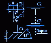
For decoupling power supply circuits of high-frequency devices by alternating current apply the so-called feedthrough capacitors. They also have three outputs: two - from one lining ("input" and "exit"), and the third (more often in the form of a screw) - from another, external, which is connected to the screen or wrapped in a chassis. This design feature reflects the conventional graphic designation of such a capacitor ( rice. 3.3, C1). The outer lining is indicated by a short arc, as well as one (C2) or two (C3) segments of straight lines with leads from the middle. A conditional graphic designation with a reference designation SZ is used when depicting a feed-through capacitor in the screen wall. For the same purpose as the feedthrough capacitors, reference capacitors are used. The lining connected to the case (chassis) is distinguished in the designation of such a capacitor by three inclined lines, symbolizing "grounding" (see Fig. rice. 3.3, C4).
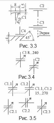 Variable Capacitors(KPI) are designed for operational adjustment and usually consist of a stator and a rotor. Such capacitors have been widely used, for example, to change the tuning frequency of broadcast receivers. As the name itself says, they allow multiple adjustment of the capacity within certain limits. This property of them is shown on the diagrams with a regulation sign - an inclined arrow crossing the base symbol at an angle of 45 °, and near it the minimum and maximum capacitance of the capacitor is often indicated (Fig. 3.4). If it is necessary to designate the KPI rotor, proceed in the same way as in the case of a feedthrough capacitor (see Fig. 3.4, C2).
To simultaneously change the capacitance in several circuits (for example, in oscillatory circuits), blocks consisting of two, three or more KPIs are used. The belonging of the KPI to one block is shown on the diagrams by a dashed line of mechanical connection connecting the control signs, and the numbering of sections (through a dot in the reference designation, rice. 3.5). When depicting the KPI of a block in different parts of the diagram that are far from one another, the mechanical connection is not shown, limited only by the corresponding numbering of sections (see Fig. rice. 3.5, C2.1, C2.2, C2.3).
Type of KPI tuned capacitors. Structurally, they are made in such a way that their capacity can only be changed with the help of a tool (most often a screwdriver). In the conditional graphic designation, this is shown by the sign of the tuning regulation - an inclined line with a dash at the end ( rice. 3.6). The rotor of the trimmer capacitor is indicated, if necessary, by an arc (see Fig. rice. 3.6, C3, C4).
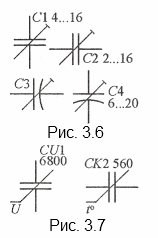 Self-regulating capacitors (or non-linear) have the ability to change capacitance under the influence of external factors. In electronic devices, variconds are often used (from English words vari(able)- variable and cond(enser) is another name for a capacitor. Their capacitance depends on the voltage applied to the plates. The letter code of the variconds is CU (U is the generally accepted voltage symbol, see Table 1.1), UGO in this case is the basic symbol of the capacitor, crossed out by the non-linear self-regulation sign with the Latin letter U (Fig. 3.7, capacitor CU1).
The UGO of thermal capacitors is similarly constructed. The letter code for this type of capacitor is SK ( rice. 3.7, capacitor SK2). The temperature of the medium, of course, is denoted by the symbol tº
Along with the most common radio components, resistors, capacitors rightfully occupy the second place in terms of use in electrical circuits and diagrams. The main characteristics of the capacitor are the rated capacity and rated voltage. Most often, fixed capacitors are used in radio electronics circuits, and much less often, variable and tuned ones.
The rated voltage of capacitors is usually not indicated on the circuits, although it sometimes occurs in some cases, for example, in high-voltage circuits of a power X-ray device, the rated voltage is often written with the designation of the rated capacitance. For oxide, they are also called electrolytic capacitors, the voltage rating is also very often indicated.

Most oxide capacitors are polar, so you can only include them in an electrical circuit with respect to polarity. To show this on the diagram, the positive overlay symbol has a "+" sign.
For decoupling power circuits in high-frequency circuits for alternating current, they use feedthrough capacitors. They have three outputs: two - from one lining ("input" and "output"), and the third from the other, outer, which is connected to the screen. This design feature reflects the conventional graphic designation of such a capacitor. The outer lining is drawn with a short arc, as well as one or two segments of straight lines with leads from the middle. With the same task as the feedthrough, reference capacitors are used. The lining connected to the case is distinguished in the designation of such a capacitor by three inclined lines, speaking of "".
Designation of variable capacitors (KPI) on the diagrams |
KPI are used for operational adjustment and consist of a stator and a rotor. Such capacitors are widely used, for example, to control the frequency of broadcasting and television receivers. KPI allow multiple adjustment of the capacity within the specified limits. This property of them is displayed on the diagrams with an adjustment sign - an inclined arrow crossing the base symbol at an angle of 45 °, and the minimum and maximum capacitances are usually written next to it). If it is required to designate the KPI rotor, proceed in the same way as in the case of a through-hole capacitor

To simultaneously change the capacitance in several circuits, blocks are used, from two, a sin and a larger number of KPIs. The belonging of the KPI to the block is indicated on the diagrams by the dashed line of the mechanical connection. When displaying the KPI of the block in different parts of the circuit, the mechanical connection is not shown, limited only by the corresponding section numbering.
Self-regulating capacitors(another name for non-linear) have the property of changing the nominal capacitance under the influence of external conditions. In electronic homemade products and designs, they often use varicondas. Their capacitance level varies depending on the voltage applied to the plates. Letter code of variconds - CU, are indicated on the diagrams with a Latin letter U
In a similar way, denote thermal capacitors. The letter code for this type of capacitor is CK and is indicated on the diagrams by the symbol t °
Due to their small size, SMD ceramic capacitors are sometimes marked with a code consisting of one or two characters and a number. The first character, if any, is the manufacturer's code (eg K for Kemet, etc.), the second character is the mantissa and the exponent (multiplier) of the capacitance in pF. For example S3 is a 4.7nF (4.7 x 10^3 Pf) capacitor from an unknown manufacturer, while KA2 is a 100 pF (1.0 x 10^2 PF) capacitor from Kemet.

Capacitors are made with various types dielectrics: NP0, X7R, Z5U and Y5V …. The dielectric NP0(COG) has a low dielectric constant, but good temperature stability (TKE is close to zero). Large SMD capacitors made using this dielectric are the most expensive. The X7R dielectric has a higher permittivity, but less thermal stability. The Z5U and Y5V dielectrics have a very high dielectric constant, which makes it possible to manufacture capacitors with a large capacitance value, but with a significant variation in parameters. SMD capacitors with dielectrics X7R and Z5U are used in general purpose circuits.

AT general case ceramic capacitors on the
based dielectric with high permeability are denoted
according to the EIA with three characters, the first two of which indicate
to the lower and upper limits of the operating temperature range, and
the third is the allowable change in capacitance in this range.
The decoding of the code symbols is given in
Z5U - capacitor with precision
22, -56% in the temperature range from +10 to +85°C.X7R - capacitor with an accuracy of ±15% in the range
temperatures from -55 to +125°C.
Marking of SMD electrolytic capacitors.

SMD electrolytic capacitors are often labeled with their capacitance and operating voltage, for example 10 6V - 10 µ F 6V. Sometimes this code is used instead of the usual one, which consists of a character and 3 digits. The symbol indicates the operating voltage, and 3 digits (2 digits plus a multiplier) give the capacitance in pF.
A cut or bar indicates a positive lead.
Symbol Voltage
For example, the capacitor is labeled A475 - 4.7mF 10V
475 = 47 x 10^5pF = 4.7 x 10^6pF = 4.7mF
The principles below code marking are used by such well-known companies as PANASONIC, HITACHI, etc. There are three main encoding methods.
The code contains two or three characters (letters or numbers) indicating the operating voltage and nominal capacity. Moreover, the letters indicate the voltage and capacity, and the number indicates the multiplier. In the case of a two-digit designation, the operating voltage code is not indicated.


