KINEMATIC CALCULATION OF A MECHANICAL DRIVE
Sequence of kinematic calculation
Drive shaft power,kW
where F t– circumferential force, kN; V- speed, m/s.
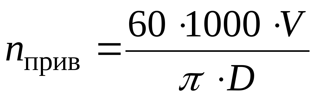
Drive shaft speed,min -1
A) For chain and slat conveyors
 ,
,
The efficiency of an electric motor is the ratio of the output power of the shaft and electrical power. These losses are the result of magnetic energy dissipation when a magnetic field is applied to the stator core. Waste losses are the losses that remain after primary copper and secondary losses, iron cuttings and mechanical losses. The largest contribution to stray losses is the harmonic energies that occur when the motor is running under load. These energies are dissipated as currents in the copper windings, harmonic flux components in the iron portion, flowing in the core of the laminate. mechanical losses. Mechanical losses include friction in the motor bearings and a fan for air cooling. Open drip hole or fully enclosed fan 1 HP cooled motors and more who work more than 500 hours a year. Options: - Transformer Form Formula Formulas. Motor speed calculation. Asynchronous motor with squirrel-cage rotor is a constant speed device. It cannot operate for any length of time at speeds below those specified on the nameplate without risk of burnout. A force is any cause that changes the position, movement, direction, or shape of an object. Work is done when the force overcomes the arsenal. Resistance is any force that prevents an object from moving. If the applied force does not cause motion, no work is done. This makes the object rotate. Torque consists of a force acting over a distance. Torque, like work, is measured in pound-feet. However, torque, unlike work, can exist even if there is no movement. Calculation Full load torque: Full load torque is the torque to generate rated power at full motor speed. The value of the torque produced by the motor at rated power and full speed can be found using the power factor and torque conversion diagram. When using a conversion chart, place a ruler along the two known quantities and read the unknown quantity on the third line. A watt is a unit of measure equal to the power generated by a current of 1 A, based on a potential difference of 1 volt. Watt is the base unit electrical energy . Horsepower is used to measure the energy produced by an electric motor during operation. This is because the synchronous speed of an induction motor is based on the power frequency and the number of poles in the motor winding. Basic formulas and engine calculations. The formulas and calculations below are to be used for evaluation purposes only. In mechanical systems, all rotating parts usually do not run at the same speed. Thus, we need to determine the "equivalent inertia" of each moving part with a certain speed of the prime mover. For variable speed devices, inertia must be calculated first at low speed. Let's look at a simple system that has a prime mover, gearbox, and load. Note: The air capacity depends on the fan speed. The developed pressure depends on the square of the fan speed. Accelerating moment. The equivalent inertia of a variable speed drive indicates the energy required to operate the system. However, starting or accelerating the system requires additional energy. If a more precise calculation is required, the following example may be helpful. The application of the above formula will now be explained with the help of an example. At any blower speed, the difference between the torque that can deliver data on its shaft and the torque required by the blower is the torque needed to accelerate. When the torque curves for motor and blower intersect, there is no torque required for acceleration. The motor then drives the fan at a constant speed and simply provides the required torque. In order to find the total time required to accelerate the motor and the blower, introstrips are separated between the motor torque curve and the fan speed curve, the ends of which approach straight lines. Each bar corresponds to an acceleration that occurs within a certain time interval. The solid horizontal lines in Fig. To calculate the total acceleration time for a direct coupled motor and blower, find the time required for the motor to accelerate from the start of one speed interval to the start of the next interval and add the incremental times for all intervals Get the total acceleration time. Orders with notes such as these cannot be processed for two reasons. First of all, the relevant product group should be consulted to see if a design is available that will fulfill the required duty cycle, and if not, to determine if the type of design required is in line with our current product line. None of the above notes provide sufficient information to calculate the required duty cycle. Information about how each step of the cycle is performed. Any special mechanical problems, features or limitations. Getting this information and checking with the product group before the order goes live can save a lot of time, expense and correspondence. The work cycle refers to detailed description a work cycle that repeats itself at a specific time interval. This cycle may include frequent starts, locking stops, reversals or stalls. These features are typically involved in batch type processes and may include drum rails, some cranes, shovels and draglines, dampers, picking or soldering drives, drawbridges, freight and personnel elevators, press extractors, some feeders, certain types of presses, hoists , pointers, boring machines, cinder block machines, key making, kneading, car pushing, shakers, washing and washing machines, and some freight and passenger vehicles . The list is not exhaustive. Loading drives must be able to absorb the heat generated during the operating cycles. Sliding devices, clutches or motors must be provided with sufficient capacity to accelerate or stop these drives or to support stalls. All events that occur during the operating cycle generate heat, which the diffuser components must dissipate. Due to the complexity of design load cycles and the extensive engineering data for each specific engine design and estimate required for calculations, it is essential that a sales engineer contact the product department to determine engine dimensions using a duty cycle. Theory and Applications Commissioning Fans and Drives Functional Testing Field Tips Basic Commissioning Requirements Wrench Requirements and Precautions Time Required to Verify Static Pressure Requirements Exceeding Design Improper Adjustment of Seat Belt System Test Guide and Sample Samples Form and Applications The fan is the heart of an air conditioning system as it is one of the largest energy consumers in a building. The commissioning and re-commissioning of fans and drives is key to ensuring that building performance goals are met throughout the life of the building. There are both indirect and direct components for fan power consumption. The indirect component refers to the system that the fan serves. The fan must supply enough energy to the airflow to overcome the system's resistance to flow. This energy consumption can be significantly altered by: fan installation considerations such as system effect Duct and fitting design and associated pressure drops; pressure drop in the component; air duct system leak; heat losses in the duct system. These topics are discussed in Chapter 11, Distribution, and Chapter 13: Return, Dump and Exhaust System. The direct fan energy component refers to how efficiently the fan can hide the energy going in its prime mover into the airflow and pressure in the fan system. This power consumption is a function of the following elements: Fan efficiency Motor efficiency Efficiency and regulation of the drive system. The fan power equation is a function of several main components: flow, static pressure, fan efficiency, and motor efficiency. To ensure the efficiency, performance and reliability of the system, commissioning efforts must be directed. Most of the advances in technology that improve the performance of these components are related to drive systems and control systems, not the components themselves. Drive and control systems can be easily upgraded to meet process requirements. If you examine a reasonably well stocked 50 year old aerodynamic fan and a similar unit straight off the production line, you will probably see only minor differences in performance. However, it is likely that the fan is capable of moving air as efficiently as a new fan. With attention to proper maintenance and equipment layout, fans can be a durable component of an air conditioning system. Commissioning of fans and drives. The following sections present the benefits, practical advice and design issues related to the reception of fans and fan drives. Field tips for functional testing. The commissioning testing requirements list the practical considerations for functional testing. Basic requirements for commissioning. Energy makes up a significant portion of a building's total energy consumption. A well-executed commissioning plan for fans and their associated drive systems ensures that systems are set up for maximum efficiency and that efficiency is maintained. The fan and drive control must be securely integrated with the overall system control strategy in such a way as to provide the intended function and performance level. 1 Check the fan size and power. The performance test results shall be judged against the accuracy of the instruments and the actual conditions at the time of the test. 2. Sharpening dampers must be checked for correct operation. Non-motorized dampers should open and close freely without binding. Failover should safely bring the drive back online. 4 Verify that the drive settings and settings provide safe and reliable system operation with maximum efficiency levels in all operating modes. Basic Precautions and Warnings. 1 The applicable caveats described in Fundamentals of Functional Testing must be observed. 2. Checking security and interlocks, checking some drive settings and trying to set up a loop will put the system at risk. This is usually done when conducting construction supervision. Test Conditions1 Tests, which are aimed at verifying the design parameters and parameters of the fan and its housing, can usually be carried out after the assembly of the unit, but before it is started. Other tests focusing on interlocks and basic control functions and power testing will require the air conditioning system to operate and move the design volume of air, but not necessarily be fully controlled. Security systems must be operational to protect cars and passengers in the event of a problem. Design issues. Review of design problems. Problems that can be solved at the design stage to improve the performance, safety and energy efficiency of the system are presented. These design issues are necessary for vendors to understand even if the design phase commissioning is not part of their scope, as these issues are often the root cause of issues identified during testing. Does the device have good access for installation, Maintenance and component replacement? Access to the fan and associated components is critical to maintaining energy efficiency and other commissioning benefits. 1 Piping should be arranged so that access units are not blocked, service routes remain open, and components such as fan coils and shafts can be removed and replaced without closing adjacent systems or central installation equipment. 2. Fan scrolls should be provided with access doors to allow the wheel to be inspected and cleaned. 3. Coils must be provided with a gap between them and access to this place for inspection of the object and cleaning, as well as the ability to install controls in the proper place. For example, space is required between the preheat coil and the next downstream coil to allow a freezing device to be installed downstream of the preheat coil. This condition is likely to occur in parallel fan systems even if equipped with rear shocks. No damper is 100% leakproof, and it doesn't take much reverse flow to set a fan wheel in motion. There are usually adjustments that need to be made to adapt this feature to the load that was used in addition to activating it. Verification of correct installation and operation should be part of the commissioning process, both during pre-start checks and through functional tests. Many drives are equipped with bypass contactors that allow the motor to run at full speed when the drive is not running. In some cases, the system may be damaged by running at full fan speed when the loads have been configured for minimum flow conditions. 4 The drive must be configured and wired to ensure that all safety interlocks are effective in all possible selector switch configurations. Some drives are designed so that the safety interlocks are effective when the drive is running, but not effective when the drive is bypassed. Some drives can also be configured so that if they are placed in local mode, any external lock will be ignored. Verifying that the drive is properly installed and functioning should be part of the commissioning process, both during pre-start checks and functional tests. Even with budget constraints preventing a motor replacement when a drive is installed, the potential for future problem and early failure can be expected. In new installations, drives and motors must be compatible with each other. Evidence shows that these eddy currents can lead to premature bearing loss, possibly within a few years on some motors. Shaft ground kits mounted on the motor provide a direct path from the shaft to the ground through the brush system. Is the drive device suitable for the application? Given the wide range of drive options available, it is important to tailor the selection to the application. 1 If direct drives are used, fan speed control for balancing must rely on less efficient approaches such as unloaders, or require a variable speed drive to be included as part of the package. 2 Variable speed drive on a constant volume valve can represent a false economy. While it minimizes balancing effort and eliminates the need for an end-to-end change or adjustment of the fan speed pulley, the drive results in a loss in fan system efficiency that increases as speed decreases. The drive also introduces operating complexity, first cost, potential electrical system problems, and the possibility of multiple system failures. These problems, combined with reduced efficiency, are likely to outweigh any modest balancing cost savings 3. Variable stepper pulleys provide flexibility and a good intermediate pitch between start and final balanced speed when the system is commissioned. Can the fan motor run in the wrong direction? For most axial fans, if the impeller were to run in the opposite direction, it moved the air in the opposite direction. With centrifugal fans, running the impeller backwards will still provide the correct direction of flow, but performance will be significantly reduced. Reverse flow or reverse thrust through most fan wheels will cause them to spin in the opposite direction. The front bent fan wheels will rotate in the wrong direction if air is blown through them in the correct direction, but they are not energized. For most single-phase motors If the motor runs in the wrong direction when power is applied, the fan will simply run in the wrong direction. So if the motor spins backwards when voltage is applied, it will spin and move in the correct direction. Problems can occur with variable speed drives when they try to run the motor in reverse rotation. Systems with operating conditions that can cause reverse flow must be designed and installed without problems and reliably deal with any problems. Both normal and emergency conditions must be considered. Common examples of situations where the potential for backflow exists include: 1 systems with parallel fans or ventilation units. Don't forget that parallel fan terminals have fans that are essentially parallel to the power supply. Series fan systems: supply and exhaust fans connected to 100% fresh air systems and fans in fan terminal boxes fed in series with respect to the supply valve. Does the air handler specification include desired options? Most fans and ventilation units are available with a variety of options, some of which are preferred in most installations and others only for special installations. Examples include: 1 Access to doors in shells and fan scrolls. 2. Lubrication lines that must be accessible from the outside of the device. 3. Basic vibration characteristics measured at the factory. 4 High efficiency motors. 5 Special conditions for vibration isolation. Factory rear traction dampers. 8 Non-sparking or explosion-proof design for hazardous locations. 9 Specialty coatings for handling abrasive or corrosive fluids. Common Problems The following problems are common with fans and drives. Static pressure requirements exceeding design. A typical problem that occurs during commissioning or commissioning is high static pressure in the fan system. When creating excess static pressure that is not required for the operation of the system, the fan consumes a significant amount of energy. This problem arises because fan selection often falls into a range where there is a difference between the braking power design requirements and the actual motor power set due to standard power ratings available in motor product lines. The difference between available sizes can become quite significant for large fans. For example, a fan with an 82 hp motor. likely to be equipped with a 100 hp engine. If the fan failed to deliver the design flow in relation to the set static load installed system, then there would be a lot of difference in speeding up the fan until the design requirements are reached without restarting the motor. This safety net may be desirable, as excess engine power can solve problems in the field. But the added energy drawn by the fans above what is intended by the design will become an energy burden that will be saved for the life of the system. Extra diligence during design and construction can prevent conditions that add unexpected static pressure to the system, which prevents the fan from needing to be started at a duty point that exceeds design. If the balancing team finds that they have excessive static pressure in the system, it is possible to lower the static pressure, which will allow the system to function at or near the intended design point, rather than increase the current energy load on the project by simply throwing energy at the problem. Incorrect adjustment of the belt drive system. For a simple reason, there are some important parameters associated with installing and adjusting these belt drive systems that are often overlooked, resulting in belt failures, poor performance, noise, reduced equipment life, and energy waste. Aligning the drive and motor pulleys is a critical step in the belt installation process. Without proper alignment, the belts will run less efficiently, wear out more quickly and, in extreme cases, be thrown off the starter pulleys. Due to the excessive tension of the belts, problems with bearings and shafts can occur due to excessive loads. In addition, new belts will stretch during the first 8-24 hours of operation; belts that were correctly installed initially will require re-tensioning after they have been started. This unforeseen situation often ignored to the detriment of drive system efficiency. Multiple belt drives will work best if the factory belt kits are installed. This ensures even distribution of drive loads between all belts, evening out wear and service life. Additional Information. Additional information for fans and drives has been developed to provide the necessary feedback for functional testing. While fans come in a wide range of designs, shapes, sizes and configurations. They are mainly divided into two categories: Centrifugal fans This type of fan imparts kinetic energy air mainly by centrifugal force. Essentially, air is drawn into the center of the fan wheel where it is trapped and contains the blades. These parcels of air then "fall" to the periphery of the wheel. The wheel itself may have an inlet on one side or an inlet on both sides. The design of the blades on the wheel can have a significant impact on efficiency, productivity and cost. Common designs are forward-curved, reverse-curved, aerodynamic, and radial. Axial fans This type of fan uses aerodynamic effects to impart air velocity to the air as it passes through the impeller. Typically, air moves along the axis of the fan and impeller compared to a centrifugal design where air enters the impeller, flowing parallel to the shaft, but exits the impeller in a radial direction relative to the shaft. Typically, the impeller for this type of fan will be similar to an airplane propeller, but with more blades. Power management strategies. Regardless of design, the rotating nature of a fan wheel can place significant structural loads on the shaft, wheel, bearings, and casing. Therefore, some care must be taken when changing fan speed in the field to ensure that the new operating point is still in the fan class rating. There are many methods used to control fan power. The most common are: Relief dampers Dampers located at the outlet of the fan can simply throttle the fan. As a general rule, this is perhaps the least expensive, but also the least desirable approach due to the damper's effect on fan exhaust. It can also be quite noisy. Inlet vanes Inlet vanes change the operation of the fan by "spinning" the air as it enters the eye of the fan. This approach is much more desirable than the unloader damper, but not as desirable as the variable speed approach. Most fans that use this approach require additional maintenance in the form of periodic lubrication, monitoring, and overstressing the mechanical blade pitch control system. Variable speed This is currently probably the most common approach to fan power control due to its efficiency, mechanical simplicity and continuous improvement of the first cost. The devices functioned by moving the sides of an adjustable drive pulley towards or away from each other. This changed the effective pulley pitch diameter and thus the output speed. As such, they tend to be more efficient than some other approaches, but they also tend to keep the fan's efficiency at or near the chosen efficiency as they change their power by changing the speed. However, this is not without its complications, but paying close attention to design and commissioning issues can easily overcome any problems, and the benefits generally outweigh the drawbacks. Although efficiency decreases with load, these drives generally provide better efficiency and idleness than some other alternatives such as variable sheave systems. Regardless of the technique used, power control systems will expose the fan and its components to a wide range of ever-changing operating conditions. The interaction of many operating points with fan components, system components and the building can lead to a number of unexpected and unforeseen problems, especially for large fans with high power. These problems can be difficult to predict and often appear as commissioning issues. Often, their viable approach to solving them is to make sure the design includes features that will allow you to fix the problem if it happens. For example, avoiding running in a triggered state can solve most of these problems. So ensuring that the disks that will be supplied for your project include this feature can give the start-up and commissioning team the tools they need to tackle this type of problem should it occur. Another desirable feature to be included in the design is vibration analysis and documentation in various operating modes for large fans, especially if they will be operated with variable capacitances and speeds. It is also possible to perform tests on the structure of a building to determine its resonant frequency and then use this information to discard drive systems. The design engineer can also predict the resonant frequency range expected for the structure, and this information can be reviewed by the team in light of the expected system performance, allowing potential problems to be identified and addressed during design. Drive Systems and Devices In all cases other than direct drive, some sort of pulley or pulley and belt system is usually connected to the fan and motor. It is not uncommon for one of these pulleys to be provided with an adjustable configuration so that the fan speed can be easily adjusted by the balancing contractor in the field. Preferably, from this point of view, there are a few backs to adjustable pulleys or pulleys: Belt life Most V-belts will provide the best life if they are operated with their outer perimeter slightly above the edge of the pulleys on which they are mounted. If the adjustable pitch pulley requires significant adjustment, it is not uncommon to break the outer perimeter of the belt under the top of the sidewalls. This results in additional wear to the belt and can significantly shorten the life of the belt. Loss of adjustment Despite its advantages, adjustment can also be a drop in adjustable tongues. It's not uncommon to accidentally lose a balanced pulley setup when changing belts, especially if the mechanic doing the job hasn't been trained on adjustable bundles and mistakenly believes that the adjust function is a convenient way to tension a belt or make a set of belts they have that they fit with. As a result, a once-balanced system is thrown out of balance and performance suffers. If the new setting provides less air than intended, then capacity problems may show up later when design loads are introduced into the system. If the settings provide more air than intended, energy can be wasted, especially if the system is one of the fixed volume reheat systems often found in hospitals or manufacturing environments. Both issues can lead to pressure ratio issues if the incorrectly configured fan is an exhaust fan. If the exhaust is dangerous, the loss of airflow can create a dangerous condition in the area served by the fan that cannot be immediately detected. Fans and there prime movers come in various mounting arrangements. This information can also be found in most manufacturer fact sheets. In addition, the physical constraints on the installed location of the fan may place limits on the type of drive device that can be used. It was too determined to solve the problem in this project, but another agreement might have prevented this. In this project, maintenance personnel will need to remove the belt and drives to inspect the fan wheel. Service Requirements Some measures may result in the impossibility of servicing the motor wheel or fan in designated place or may block access to another room fan component Balancing The belt and pulley system provides a convenient way to adjust fan speed for balancing. Direct drive fans do not have this option and require other tuning methods for final balance such as variable pitch or variable speed drive. Adjustable blades don't have to be automated, but are labor intensive to install compared to changing a pulley. Variable speed drives are attractive in terms of ease of use, but add unnecessary cost, complexity, and failure modes to a fixed volume system. Heat gain. Since they are doing work on the airflow and the air is being compressed, all fans will show a temperature rise on them even if the motor is not in the airflow. For large fans with big engines this can be a significant load on the system that could be avoided by mounting the motor out of the airflow. These advantages must be weighed against the complications that can arise for some machines in terms of sealing the drive shaft when it penetrates the housing and vibration isolation. Vibration and soundproofing. The method by which vibration and sound isolation are performed can also influence the choice of position. Mounting the entire fan and drive on an insulating mount will further soundproof the assembly by placing it inside an acoustically treated fan housing by placing the motor in the airflow. By their nature, direct drive fans usually have vibration isolation problems that occur when the motor is installed. A hidden but sometimes significant aspect of vibration isolation techniques has to do with how the equipment will be sensitized. It is becoming increasingly common for manufacturers to offer two parallel fans in packaged equipment. Usually space constraints, redundancy requirements, or both drives this design. When they are busy, there are several issues to consider. Bumper dampers are typically used to prevent air from recirculating from an active fan to an inactive fan. However, if they are not carefully applied, there may be some operational difficulties that may arise during the commissioning process. Surge If two identical fans are running in parallel, there is a possibility of voltage spikes between the two fans. This is because it is very difficult to create two fans that are exactly identical and then make them work at exactly the same point on their performance curve. Because the fans are connected to the same system, but that system places them at slightly different points on their operating curves, pressure fluctuations can occur as the fans move and interact in an attempt to find a mutually acceptable operating point. The effects of this can range from subtle to noise to fan damage. This is the same effect that you experienced as a child on a playground carousel. While less common than other designs, radial blade fans are sometimes found in exhaust systems, especially exhaust systems that handle materials such as dust or other particulate matter, or when required high pressures. This temperature rise can be calculated in the same way as the thermal power of the fan, but the power of the motor in the current operating state is used. This should not be confused with the overvoltage that can occur in a single valve if it is operated at a point on its curve where the pressure difference across it combats the ability of the fans to generate this pressure difference causing sporadic flow inversions through the impeller.
- Electric motor efficiency.
- Losses from losses.
where z sv- the number of teeth of the traction sprocket; t- step of the traction sprocket, mm.
B) For belt conveyors, travel and turning mechanisms, disk feeder, winches, etc.
 ,
,
where D- diameter of the actuator, mm.
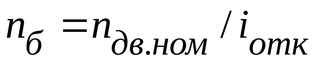
Overall drive efficiency
 ,
,
where 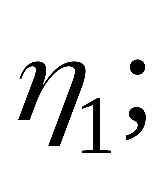

 ... - The efficiency of individual links of the kinematic chain, the approximate values of which are recommended to be taken from table 1.
Table 1.
Guideline values for the efficiency of the components of the drive
|
Links of the kinematic chain |
Designation | |
|
Gears: cylindrical closed cylindrical open conical closed conical open |
| |
Worm gear closed |
| |
|
Belt drives open: V-belt flat-belt |
| |
|
Chain transmission open |
| |
|
Coupling |
| |
|
Bearings (one pair): slip |
|


Estimated motor power,kW
 ,
,
where  - power on the drive shaft, kW.
Motor selection
It is necessary to select an AC motor with a power
 (kW) closest to
  .
.
When selecting, it is allowed to overload the engine up to 6% at a constant load. Estimate the motor overload using the formula:  , where
  - the smallest of the power values
  and
and  .
.
Power value  corresponds, as a rule, to four electric motors with a certain synchronous speed:
 =
750; 1000; 1500; 3000min -1
. At a constant load, the calculation of the drive is carried out according to the rated speed of the electric motor
=
750; 1000; 1500; 3000min -1
. At a constant load, the calculation of the drive is carried out according to the rated speed of the electric motor  . AC motors of the AIR series are presented in Table 2.
Table 2.
Technical data of AIR series engines
|
Power N, kW |
Synchronous frequency, rpm |
|||
Notes.
Above the line is the type of engine, below the line is the rated speed.
Engine designation example: “AIR100 engineL2 TU 16-525.564-84"
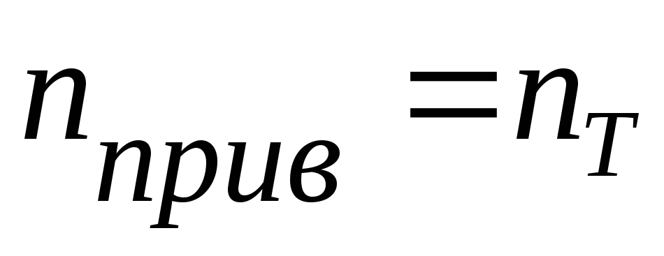
Overall Drive Ratio
 , where
  - frequency of rotation of the drive shaft, min -1
.
- frequency of rotation of the drive shaft, min -1
.
Calculated for each value of the rated speed of the electric motor at the assigned power  .
.
Breakdown of overall drive ratio
A) Assign the gear ratio of the open gear of the drive  according to the recommendations of the table. 3, taking into account the following: a smaller gear ratio is preferable, which will provide smaller transmission dimensions.
Table 3
Values of gear ratios of mechanical gears
|
Transmission type |
gear ratio |
|
|
limiting |
||
|
Toothed cylindrical: closed; open | ||
|
Gear bevel: closed; open | ||
|
worm | ||
|
belt | ||
|
Planetary simple single row | ||
For a gear train, the gear ratio must be matched to the standard range of nominal gear ratios u according to GOST 2185:
1st row: 1; 1.25; 1.6; 2.0; 2.5; 3.15; 4.0; 5.0; 6.3; 8.00; ten; 12.5...
2nd row: 1.12; 1.4; 1.8; 2.24; 2.8; 3.55; 4.5; 5.6; 7.1; 9.0; 11.2…

where n is an integer.
 .
.
Note
.
If there is no open gear in the drive, then  .
.
C) For a gear reducer, the gear ratio must be adjusted to the standard series of nominal gear ratios u
according to GOST 2185; for a worm gearbox with a single start worm, the gear ratio is an integer. In this case, the deviation of the actual gear ratio of the gearbox  from nominal
  should not exceed 2.5% at
  4.5 and 4% at
  4.5.
4.5.
The deviation is estimated by the formula: 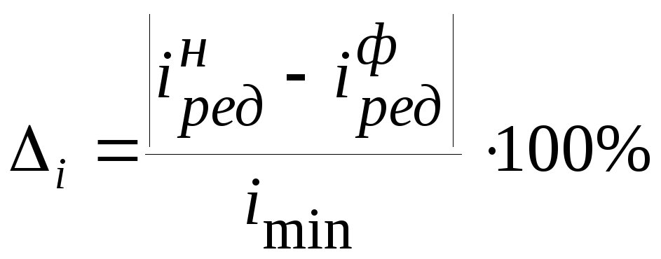 ,
,
where  - the smallest of the gear ratio values of the gearbox
  and
and  .
.
Note.
For single stage gearbox  ,
,
whereu- nominal gear ratio of the gear stage.

Specify the type of electric motor for the assigned breakdown of the drive gear ratio (Table 2).
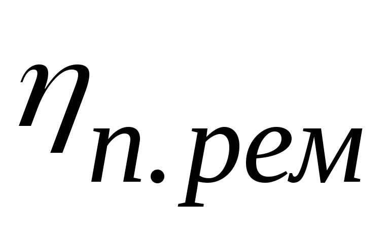
Power per drive shaft,kW:
where 
 ... - efficiency of individual links of the kinematic chain.
Drive Shaft Speed,min -1 :
high speed gear shaft
 when connected with a coupling;
 in the presence of an open transmission;
 when connected with a coupling;
 with an open transmission.
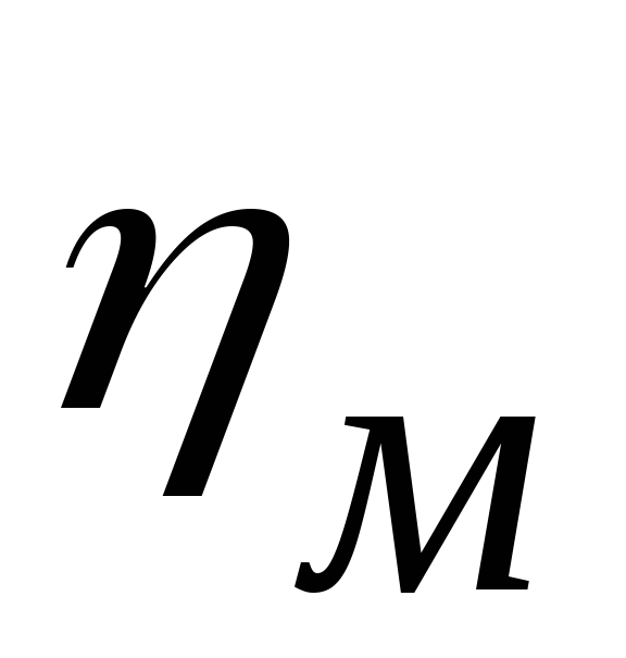
Torque on each drive shaft,Nm:
 ,
,
where i – drive shaft index.
Jul 03 2017
It is easier to use current clamps, only there is one but. At idle, even at high speeds, the engine is powerless to develop full power.
Below is a table according to which you can judge the parameters of the device by mode. Doesn't solve the problem entirely. Let's see how to determine the power and current of an electric motor with simple methods.
Determining the motor current
It is easier to use current clamps. A device that allows you to remotely assess the magnitude of tension magnetic field around a single wire.
Covering the power cord with a ring, we get a value equal to zero. The fields are directed oppositely to the phase and zero conductors.
You will need to work to make an outlet with separate wires, shown in the picture.
Here we see:
- Wooden base. The obvious way out, it is customary to mount the socket on the insulator. It's easier to get a small piece of board.
- The surface-mounted socket is shown disassembled: the base, the body are located separately.
- Remove the insulation from the power cord to cover each core separately.
- Find a collapsible plug. It is forbidden to use for powerful instruments, but we will take measurements for a short period of time, accompanied by full control. Or buy a standard extension cord in the store, remove the outer insulation from the power cord.
The socket is mounted on the board, take the trouble to securely clamp the wires, blocking the possibility of breaking, slipping.
It's easier to do it by using the insulation trim, the photo is shown. We press it with a self-tapping screw, the long life of the test outlet is ensured.
When putting on the case, you will need to wind a little electrical tape around the cord for better pressing.
It turned out to be an auxiliary tool for carrying out measurements with current clamps.
At idle, the value will be lower than the nominal value.
It has been noticed that during acceleration, full power is required from the engine, instantaneous, given out by the pincer screen, are close to nominal.
For example, for the device in the photo - 3.2 A, with a voltage of 231 volts, it gives 740 W (nominal 750 W). At startup, it will be seen: the current rises sharply, then quickly drops. You need to have time to spot the top of the mountain.
Note: current clamps give readings at regular short intervals, it is difficult to detect the peak the first time.
Set the spindle speed to the highest, patiently pull the trigger, trying to catch the top. We succeeded the third time.
To take a more or less suitable picture, the experiment was carried out a dozen and a half times (the shutter was released with a delay, it was difficult to catch the moment).
And after that, the photo turned out to be only 3.1 A (we think readers believe the authors about 3.2 A).
During the experiment, a value of 4 A was obtained once, which we attribute to random jumps in the network current plus errors.
You make sure: the peak is repeated (at least 2 times out of five).
As a result, the power of the collector motor of an electric drill is approximately determined. We want to say right away: there is no unambiguous dependence of the idle current on the power rating.
In nature, there are quite complex formulas, it is quite difficult to use them. Practical application is more difficult. We give a table of approximate ratios asynchronous types engines.
The information makes it possible to understand how to estimate the rated power of the motor by the no-load current.
The voltage must be rated, bulky devices need to be warmed up before work.
So says GOST R 53472. The period is determined by the type of bearings.
Be afraid to make a mistake, take the maximum value:
- Up to 1 kW of power, the warm-up time is below 10 minutes.
- Rated power 1 - 10 kW, warm-up time about half an hour.
- Rated power 10 - 100 kW, warm-up time up to an hour.
- Rated power 100 - 1000 kW, warm-up time up to two hours.
- Rated power over 1 MW, warm-up time up to three hours.
How to estimate the approximate power? We explain. The list is given to those wishing to take measurements more precisely.
For a rough estimate, we use the table, avoiding brainwashing. The collector motor of the drill did not warm up at all before measurements at room temperature.
Most readers are devoid of current clamps. Most multimeters allow you to measure current, the scale is limited to 10 A.
note , at the maximum limit, the red wire should be connected to another socket (shown in the photo) .
Near the hole in Russian ( English language) it is written: the time of operation with the measurement mode does not exceed 10 seconds (MAX 10SEC) followed by a quarter-hour break (EACH 15MIN). Otherwise, the multimeter operation is not guaranteed, the input is without a fuse (UNFUSED).
Tells the instructions. The multimeter crashes into the circuit. One wire needs to be opened for measurements. Together we will think about whether it is economically profitable.
Look at the picture of the receipts. The clampmeter means current clamps, a simple tester is designated 1SK.
It can be seen that both devices cost less than 400 rubles, because the household needs both.
The multimeter will allow you to evaluate the current up to 10 A, a very short operating time. The pliers work much rougher, one scale reaches the limit of 1000 A.
The conclusion is obvious - it is required to approximately determine the current of the electric motor, a "terminal" is used. You need accuracy, use a tester ( rated current below the limit).
Measure motor power
The power of the electric motor is composed of active, reactive components. Enterprises are subject to a penalty fee. Therefore, it is important to understand the measured quantities.
The current clamp instruction writes: RMS current is estimated. Pure mathematics.
This means: the device makes a sample of a certain interval, takes the root of the sum of the squares of individual measurements, divided by the total number.
Let's compare it to averaging over a certain period of time. Active current, full, reactive (hardly). The question needs to be clarified: the current clamps shown in the photo, with enviable regularity, give the power of the devices 11% below the nominal value.
Read also:
Checked electric heaters, irons, hair dryer. Power is underestimated by a single value. The literature says: Root Mean Square (RMS) shows the total amount of current.
Physically flows through the wire. The calculation is carried out for a sinusoidal form, there will be deviations if the requirement is not met.
Current clamps simply lie. If they showed the active part, for the engine the values \u200b\u200bwould be significantly lower than for the heater. The load is purely active, the windings give a strong imaginary component.
The current clamp must be calibrated before use. The easiest way to do this is using purely active heaters (oil). The ability of current clamps to measure active power separately is usually indicated in the instructions.
Professionals say: such products are the product of the imagination of amateurs
Engines give a large load in the reactive spectrum. People put up, or put capacitor units that compensate for the inconsistency, aligning the phase. You can read about such household products on sites selling appliances like Ekonor.
The meaning of the box is like a block of capacitors to compensate for reactive power. Please note: for professional stations, the limit expressed by VAR is indicated, for Econor the parameter is hushed up. One radio amateur counted the figure. It turned out that 150 VAR is compensated.
Probably enough for low-power devices, the engines will be elephant pellets. Asynchronous machines give 40% reactive power, energy is wasted. The benefits are pennies.
Please note: with an isolated neutral, problems are added. Current flows in one phase, leaves - the other. The effect can be subtracted.
The neutral is isolated - it turns out that the effect of one wire will be measured twice: input, output. Try adding the three values, then dividing by two. A rough method will be approximately correct.
Calculate the power consumption of the engine
We propose to determine the type of engine. Helps to make a badge. The apparent power is indicated (reactive plus active, connected through the cosine of the phase angle, called the power factor).
If the type of engine is known (found out, guided by the images, appearance), reference books will allow you to find the power.
No wonder: the dimensions are closely related to the parameter, each manufacturer wants to save as much as possible with the release of products.
Dimensions are optimized, a typical set of parameters is as follows:
- Shaft diameter.
- The height of the axis from the base (bed).
Accordingly, it is possible to understand the details without tools. You will see that information of a similar kind can be found for almost any type of motor.
The nameplate has been torn off, you can spend some time looking for similar models on the Internet. Russia is inferior to China in the variety of electric motors. The chance of success is high.
We believe that we have listed the available methods for determining power and current.
It is not a big problem to spend 1000 rubles, getting the necessary funds.
Considering that the ruble is burning, the move will seem reasonable.
It is easier to determine the power of an electric motor using a reference book. The shaft must be measured with a caliper.
We are finishing the review, we hope regular readers know the differences between an asynchronous motor and a collector motor. We omit the differences.
Please also note: suffer from high starting current asynchronous motors. The collector spread is low.


