Modifications of electric motors differ from each other, as well as their defects. Not every malfunction can be diagnosed with a tester, but in most cases it is quite possible.
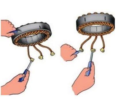
Repairs begin with a visual inspection: are there any damaged parts, is the electric motor flooded with water, is there a smell of burnt insulation, and so on. The winding in an induction motor can burn out due to a short circuit between two adjacent turns. The unit overheats due to overloads, the occurrence of high currents.
Often, burnt windings are visible during visual inspection, in which case any measurements will be superfluous. When there is no chance of a fix, you need to remove and replace the windings with new ones. Sometimes it is necessary to check the motor more carefully.
First you need to study the configuration of the motor, for example, which windings are used. All rotating machines have two parts: the stator and the rotor.
In electric motors direct current there are:
- excitation winding, which is important for production magnetic field. It allows you to convert energy from mechanical to electrical and vice versa;
- armature winding that carries the current load and regulates the alternating current to reduce eddy losses.
Engine alternating current usually consists of two parts:
- a stator having a coil for generating a rotating magnetic field;
- a rotor attached to the output shaft and designed to produce a second rotating magnetic field.
How to check the integrity of the motor windings?
Using a multimeter and a few tools at hand, you can check:
- asynchronous engines one-, three-phase;

- collector electric motors of direct, alternating current;
- asynchronous motors with squirrel-cage, phase rotor.
Coil winding testing
There is a simple test used to check the condition of the motor coil. Why measure the resistance of the windings, which varies depending on the length, thickness and material of the wire. If the resistance is too low, this indicates short circuit insulation between turns.
You can use a multimeter, but it's better to check it with a megger because it uses more high voltage when checking resistance. This eliminates false readings caused by motor coil inductance.

The test shows the quality of the wire insulation, which is determined by the resistance of the measured part of the system. The results obtained are compared with the tabular data of permissible cable insulation resistances up to 1 kV, set out in the electrical installation rules (PUE). Based on the results of the check, a failure can be predicted before it actually happens. This allows the production shop to repair or replace equipment during operation.
How the motor coil is checked with a multimeter can be seen in the video:
Anchor Diagnostics
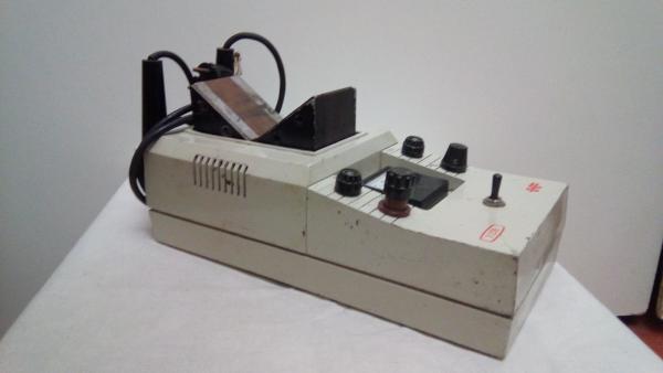
You can also check the health of the electric motor using a special digital armature tester E236. For this, an anchor is placed on the prism of the device, which is then connected to the network.
The diagnostic process includes the following steps:
- have a hacksaw blade parallel to the groove of the part under study;
- holding the metal with one hand, slowly turn the anchor with the other.
In the presence of an interturn short circuit, the web close to the groove will begin to vibrate and be attracted to the mechanism.
A visual demonstration of checking the anchor is shown in the video:
How to ring the electric motor on the stand
To quickly ring a break in the engine circuits, you can use a work stand with a DC source, an inverter, a digital voltmeter, a voltage comparator, a light indicator and a break buzzer.

On it, you can determine the interturn circuit.
Conclusion
It is far from always possible to purchase expensive special-purpose devices. Therefore, it is important to know how to check the engine with a simple multimeter, a very necessary electrical measuring device in the household. It replaces many of the separate tools needed to test circuits.
You can watch the video lesson of checking the stator for a break here:
Not all homes have expensive special-purpose appliances. Therefore, you need to know how to ring an electric motor with a multimeter: as a rule, such an apparatus should be at home.
Electric motors come in various modifications, their malfunctions also differ. Not every breakdown can be diagnosed with a conventional tester, but the vast majority are quite real.
Any repair begins with a visual inspection: are there any broken parts, is the engine flooded, is there a smell of burnt insulation, and much more. Often, burnt windings are visible to the naked eye, in which case any measurements will be superfluous: such an apparatus is immediately sent for rewinding. But sometimes a more thorough check is required.
- Regular asynchronous
- For three phases
- two-phase
- Other models
Regular asynchronous
Asynchronous electric motors are most often used in the two most common versions: three- and two-phase. Each of these models has its own nuances that need to be dealt with.
For three phases
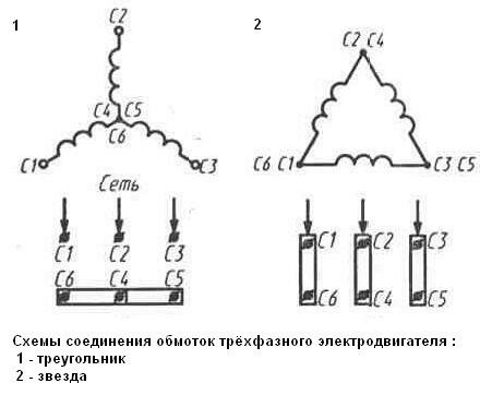
Any, even the most complex unit, has only two faults: the lack of contact where it should be, and its presence in the place where it should not be. An AC motor, three-phase, consists of three coils connected either in a star or in a delta. The performance of such electrical machine depends on correct winding, reliable contacts and high-quality insulation.
In the absence of a megohmmeter, it will not be possible to check the short to the case qualitatively, but it is still approximately possible. To do this, you need to set the resistance measurement values \u200b\u200bon the device to the maximum - megohms. Of course, this is not 500 or 1000 volts, however, with a “deaf” ground, it will be visible even at low voltage.
Make sure the motor is de-energized - an attempt to measure the resistance in the circuit connected to the electric. network will damage the device. Further calibration is necessary: set the arrow to the zero position (with the probes closed).
Before any measurement of resistance, it is important to briefly connect the probes to each other to make sure that the device is working, and also that all settings are set correctly.
We connect one of the probes to the engine housing. We make sure that there is a contact by connecting another contact of the ohmmeter to the case and observing the readings of the device. If everything is fine, with this probe we alternately touch the output of each of the three phases. With good insulation, such a test should reveal a very high resistance - hundreds, or even thousands of megohms.
Someone may object that according to the rules, the insulation resistance is not higher than 0.5 MΩ. This is true in relation to a megohmmeter with a power source of at least 500 V. We do measurements with a conventional tester with batteries that have an EMF of no higher than 9V. And at what voltage will our engine work? At 380 or 220 volts, therefore, you need to understand this difference and remember that, according to Ohm's law, the resistance value also depends on the voltage.
At the next stage, we verify the integrity of each of the three windings. For this purpose, it is enough just to ring the three ends that go out into boron el. engine. We do not yet have the task of making any serious measurements: if the winding is open, what's the point of checking something else? It is necessary to eliminate this damage and only then move on.
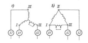
Now you can try to determine the short-circuited turns. Sometimes it can be seen visually. If not, we define it differently. With a short-circuited winding, there will be an asymmetric current consumption from el. networks. When connected with a “star”, if the A3 winding is damaged, the ammeter will determine the increased value in the A3 circuit, as can be seen in the figure. If we have a "triangle", the greater value will be in A1 and A3 - the ends connected to the faulty section.
two-phase
 An electric motor with two coils is more often called single-phase, since it is connected to a conventional electric motor. networks. With an ohmmeter, you need to ring the starter and working winding. The starting resistance is 1.5 times higher than that of the working one - it is necessary to build on this.
Take an old-fashioned washing machine as an example. Its single-phase motor has three outputs. The largest resistance between the ends indicates that these are two coils connected in series. It remains to find the middle point with an ohmmeter - this way the ends of each of the coils will be determined separately.
Do not forget about the resistance to the case - there should not be a breakdown. If the resistance is small, then the stator must be rewound. Still, if there is such an opportunity, it is better to make such a measurement with a megohmmeter, with a voltage of 500 or 1000 volts.
Other models
Single-phase collector el. engines can also be measured using the device.
- With a device turned on by units of ohms, we measure the resistance of the collector lamellas in pairs. The received data must be the same.
- Now we measure the resistance between the collector and the armature body. It must tend to infinity.
- The next step is to check the stator winding of a single-phase device.
- As we did with the armature - we measure the resistance between the terminals and the stator housing. It should be as big as possible.
Turn-to-turn short circuit cannot be determined with a conventional device. It can be detected with a special device designed to find armature faults.
A DC motor is a complex electrical car. The resistance of the excitation and additional poles is low, so they are checked either with a microohmmeter or with a double bridge.
The armature can be measured with a special voltmeter-ammeter method. To do this, use a probe with springs and good insulation.
The brushes are removed from the anchor, a low constant pressure 4-6 volts. Millivoltmeter measure the voltage drop between these plates. The resistance is calculated according to the formula: R=U*10 -3 /I. In the same way, the value on other plates is measured. They should differ from each other by no more than 10%.
Most of the malfunctions that occur in email. engines are diagnosed with a conventional multimeter. However, for a more serious diagnosis of the health of the devices, special devices are used that are too expensive for domestic use, but having enough knowledge and experience, sometimes you can do without them.
In this article I want to talk about how to detect malfunction in the power supply circuit three-phase motor and how to check the engine itself.
Let's start in order.
1. The first thing to do is check the presence of voltage on the circuit breaker (AB) or magnetic starter , i.e. Is there voltage coming from the power supply? You can check the voltage withcontrol lamp , voltmeter or electrical tester where there is a voltmeter. I do not advise using a voltage indicator, because. You will determine the presence of the input voltage, but the absence of zero is not.
2. Check it yourself circuit breaker and magnetic starter for serviceability. Measure the voltage at the input contacts of both devices, and then at the output (the machine must be turned on and the "Start" button pressed if it is magnetic switch) going to the electric motor. If faulty circuit breaker(no voltage), then replace it with a similar voltage (220 or 380V) and current strength (A). If there is no voltage at the output contacts of the magnetic starter, then the contact plates are most likely burned out. If possible, then replace them, if not, then replace the entire starter with a similar one.
Fault: magnetic starter does not work.
Check for voltage at the contacts of the starter coil. It should be remembered that the coils are 220V and 380V.
If there is no voltage, then replace the coil or starter. If voltage is applied, then it is necessary to "ring" the coil for the integrity of the winding. This can be done with the help of an electric tester (buzzer) or an electric drill.
We check the serviceability and integrity of the "Start" and "Stop" buttons.
Button connection diagram:
3. Check the integrity of the electrical wire (cable) going to the electric motor.
You can also check with a test lamp or a voltmeter. We turn off the machine (AB), disconnect the wires from the electric motor. Then we turn on the machine and check the presence of voltage on the wires. Caution, stressful work!
If there is a possibility that a short circuit has occurred in the cable (soldering and wire breakage), then it is necessary to check the wires for a short circuit to each other. We turn off the machine, disconnect the wires from the electric motor. With the help of an electric tester (buzzer) or an electric break, we check the wires in turn for a short circuit to each other.
4. We check the integrity of the windings of the electric motor itself.
Turn off the power supply (automatic).
It is better to disconnect the power wires from the electric motor.
In his Everyday life we are constantly confronted with different electrical appliances that make our work much easier. Almost all of them have in their design an engine powered by electricity to perform a certain work.
Sometimes, for various reasons, it malfunctions. We have to determine its performance, identify and eliminate breakdowns.
How an electric motor works
Let us immediately make a reservation that we will not resort to complex technical descriptions and formulas, but we will try to use simplified schemes and terminology. We also take into account that work with electric motors in electrical installations is dangerous. Trained, trained personnel are allowed to them.
Attention: Self-repair of the electric motor by unskilled workers can end tragically!
Kinematic scheme
According to the mechanical design, any electric motor can be represented as consisting of only two parts:
1. permanently fixed, which is called a stator and is attached to the body of the machine, mechanism or held in the hands, as on a drill, puncher and similar devices;
2. movable - a rotor that makes rotary motion transmitted to the actuator.
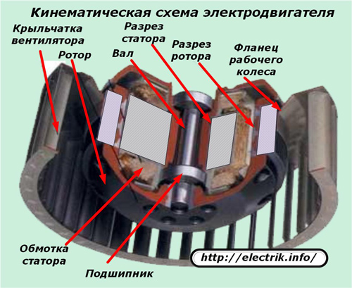
Both of these halves are completely separated from each other, but are in contact through bearings. Nowhere else and in no place do they purely mechanically contact. The rotor is inserted inside the stator and rotates completely freely in it.
This ability to rotate must be evaluated first of all when analyzing the performance of any electrical machine.
To check the rotation you need:
1. completely remove the voltage from the power circuit;
2. try to manually spin the rotor.
The first action is necessary requirement safety rules, and the second - a technical test.
It is often difficult to estimate rotation due to the connected drive. For example, the motor rotor of a working vacuum cleaner is quite easy to spin with a hand movement. To turn the shaft of the working punch, you will have to make an effort. It will not work at all to scroll the shaft of a motor connected through a worm gear due to the design features of this mechanism.
For these reasons, the evaluation of the rotation of the rotor in the stator is carried out with the drive turned off and the quality of the bearings is analyzed. Movement can be hindered by:
wear of sliding pads;
lack of lubrication in bearings or its incorrect application. For example, ordinary grease, which is often filled with ball bearings, thickens in the cold and can cause poor engine starting;
ingress of dirt or foreign objects between the movable and stationary parts.
Noise during engine operation is created by faulty, broken bearings with increased play. For its quick assessment, it is enough to shake the rotor relative to the stationary part, creating variable loads in a vertical plane, and try to push it in and out along the axis. On many models, slight backlash is considered acceptable.
If the rotor rotates freely and the bearings work well, then you need to look for a malfunction in the electromagnetic circuits.
Wiring diagram
For any engine to work, two conditions must be met:
1. apply the rated voltage to its winding (or windings for multi-phase models);
2. electrical and magnetic circuits must be in good condition.
Where to check motor supply voltage
Consider the first position on the example of the design of an electric drill with.
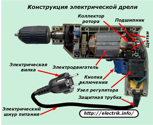
If a working drill has a plug inserted into a socket with voltage supplied, then this is not enough to start the engine. You will also need to press the power button.
Only then will the electric current from the plug through the cord through the triac control unit and the contacts of the pressed button come to the brush unit located on the collector, and through it can get to the winding.
To summarize: it is possible to conclude that the drill motor is working properly only after checking the voltage on the brushes of the collector assembly, and not the plug contacts. The above example is a special case, but reveals general principles Troubleshooting specific to most electrical devices. Unfortunately, some electricians hastily neglect this provision.
Types electrical circuits electric motors
Electric motors are designed to run on direct or alternating current. And the latter are divided into:
synchronous when the speed rotor speed and stator electromagnetic field match;
asynchronous - with a lagging frequency.
They have different design features, but the general principles of operation, based on the effect of the rotating electromagnetic field of the stator on the field of the rotor, which transmits rotation to the drive.
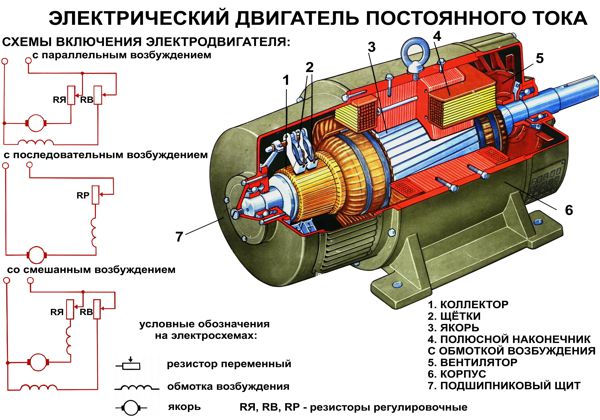
DC motors
They are made for use as coolers for computer devices, starters cars, powerful diesel stations, combine harvesters, tanks and other tasks. One of these devices simple models shown in the picture.

The stator magnetic field in this design is created not by permanent magnets, but by two electromagnets assembled on special cores - magnetic cores, around which coils with windings are located.
The magnetic field of the rotor is created by the current passing through the brushes of the collector assembly along the winding laid in the grooves of the armature.
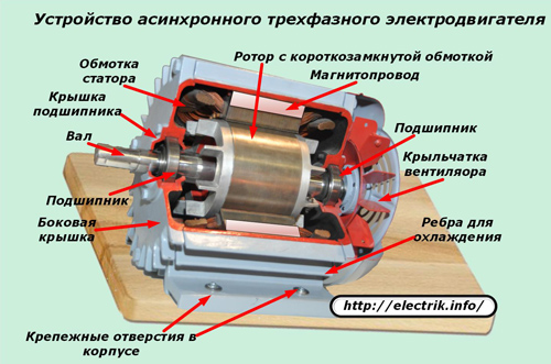
AC induction motors
The section of one of the models shown in the picture shows a certain similarity with the previously considered device. The design differences are in the implementation of the rotor in the form of a short-circuited winding (without direct current supply to it from the electrical installation), called the "squirrel wheel" and the principles of the arrangement of the turns on the stator.
AC synchronous motors
They have the windings of the stator coils located at the same offset angle between themselves. Due to this, an electromagnetic field rotating at a certain speed is created.

Inside this field, a rotor electromagnet is placed, which, under the influence of applied magnetic forces also begins to move with a frequency synchronous with the rotation speed of the applied force.
Thus, in all considered engine schemes, the following are used:
1. wire windings to amplify the magnetic fields of single turns;
2. magnetic circuits for creating paths for the flow of magnetic fluxes;
3. electromagnets or permanent magnets.
Some motor designs, called collector motors, use a circuit for transmitting current from a stationary part to rotating parts through a brush holder assembly.
In all these technical devices, various malfunctions can occur that affect the operation of a particular engine.
Since the magnetic core is manufactured at the factory from special steel plates assembled with high reliability, the breakdown of these elements occurs very rarely, and even then under the influence of an aggressive environment that is not provided for by the operating conditions or due to unforeseen extreme mechanical loads on the case.
Therefore, the verification of the passage of magnetic fluxes is practically not carried out, and all attention in case of malfunctions of electric motors, after assessing the mechanics, is turned to the state of the electrical characteristics of the windings.
How to check the brush assembly of the commutator motor
Each collector plate is a contact connection of a certain part of the continuous armature winding and an electric current passes through its connection to the brush.
For a serviceable engine, this node creates a minimum that does not have a practical effect on the quality of work and output power. Appearance plates are clean, and the gaps between them are not filled with anything.
![]()
Engines that have been subjected to severe stress have dirty manifold plates with traces of graphite dust, crammed into the grooves and worsening the insulating properties.
The motor brushes are pressed against the plates by the force of the springs. Graphite wears off over time. Its rod wears out along the length, and the spring pressing force decreases. With the weakening of the contact pressure, the transient increases electrical resistance, which causes sparking in the collector.
As a result, increased wear of the brushes and copper collector plates begins, which can cause engine failure.
Therefore, it is necessary to check the brush mechanism, inspect the cleanliness of the surfaces, the quality of the brushes, the working conditions of the springs, the absence of sparks and the appearance of an all-round fire during operation.
Contaminants are removed with a soft cloth moistened with a solution of technical alcohol. The gaps between the plates are cleaned with crows made of hard, non-resinous wood. Brushes are rubbed with fine-grained emery cloth.
If potholes or burnt areas appear on the collector plates, then the collector is machined and polished to a level at which all irregularities are eliminated.
A well-fitted brush assembly should not create sparks during operation.
How to check the condition of the insulation of the windings relative to the housing
To detect a violation of the dielectric properties of the insulation relative to the stator and rotor, it is necessary to use a device specially designed for this purpose -.
It is selected according to the output power and voltage.

Initially, the measuring ends are connected to the common terminal of the winding leads and the body grounding bolt. In the assembled motor, electrical contact between the stator and rotor housings is created through metal bearings.
If the measurement shows normal insulation, then this is quite enough. Otherwise, all windings are disconnected and an insulation fault is searched for by measuring and inspecting individual circuits.
The reasons for the poor condition of the insulation can be different: from mechanical damage to the layer paintwork wires to high humidity inside the case. Therefore, they must be precisely defined. In some cases, it is enough to dry the windings well, while in others it is necessary to look for places with scratches or scuffs to exclude leakage currents.
Article I talked about how to check, find and fix problems in collector electric motors, which differ in that they have a brush-collector assembly. Now I will tell you how to check, troubleshoot and repair an asynchronous electric motor, which is the most reliable and easiest to manufacture of all types of motors. They are less common in everyday life (in a refrigerator compressor or in a washing machine), but for that often in a garage or workshop: in machine tools, compressors, etc.
Repair or check do-it-yourself asynchronous electric motor will not be hard for most people. The most frequent breakdown in induction motors is the wear of the bearings, less often the breakage or dampness of the windings.
Most faults can be identified by external inspection.
Before connecting or if the motor has not been used for a long time, it is necessary to check the insulation resistance of it with a megger. Or if there is no familiar electrician with a megohmmeter, then it does not hurt to disassemble it and dry the stator windings for several days for preventive purposes.
Before starting repairs electric motor, it is necessary to check the presence of voltage and the serviceability of the magnetic starters, thermal relay, connection cables and capacitor, if any, in the circuit.
Checking the electric motor by external inspection
Full inspection can be carried out only after disassembling the electric motor, but do not rush to disassemble immediately.
All work is carried out only after shutdown power supply, checking its absence on the electric motor and taking measures to prevent its spontaneous or erroneous switching on. If the device is plugged into an outlet, then just remove the plug from it.
If there are capacitors in the circuit, then their conclusions must be discharged.
Check before starting disassembly:
- play in bearings. Read how to check and replace bearings.
- Check paint coverage on the hull. Burnt or peeling paint in places indicates engine heating in these places. Pay special attention to the location of the bearings.
- Check the paws fastening the electric motor and the shaft together with its connection with the mechanism. Cracks or broken legs must be welded.
For example, at the motor from the old washing machine there are three conclusions. The greatest resistance will be between two points, including 2 windings, for example 50 ohms. If you take the remaining third end, then this will be the common end. If you measure between it and the 2nd end of the starting winding, you will get a value of about 30-35 ohms, and if between it and the 2nd end of the working winding, about 15 ohms. 
In 380 volt motors, connected according to the scheme, it will be necessary to disassemble the circuit and ring each of the three windings separately. Their resistance should be the same from 2 to 15 ohms with deviations of no more than 5 percent.
Definitely need to call all windings between themselves and on the body. If the resistance is not great to infinity, then there is a breakdown of the windings between themselves or on the case. Such motors must be put into winding rewinding.
How to check the insulation resistance of the motor windings
Unfortunately, can't check with a multimeter the value of the insulation resistance of the motor windings, this requires a 1000 volt megger with a separate power source. The device is expensive, but every electrician at work who has to connect or repair electric motors has it.
When measuring one wire from the megohmmeter is connected to the body in an unpainted place, and the second in turn to each winding terminal. 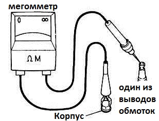 Then measure the insulation resistance between all windings. If the value is less than 0.5 Megoma, the engine must be dried.
be careful, to avoid injury electric shock do not touch the measuring clamps during measurements.
All measurements are taken only on de-energized equipment and for a duration of at least 2-3 minutes.
How to find an interturn circuit
The most difficult is the search for an interturn circuit, at which only a part of the turns of one winding is closed to each other. It is not always detected during an external examination, therefore, for these purposes, it is used for 380 Volt motors - an inductance meter. All three windings must have same value. With an interturn circuit, the damaged winding will have a minimum inductance.
When I was in practice 16 years ago at the plant, electricians used a bearing ball with a diameter of about 10 millimeters to search for turn-to-turn short circuits in a 10 kilowatt asynchronous motor. They took out the rotor and connected 3 phases through 3 step-down transformers to the stator windings. If everything is in order, the ball moves in a circle of the stator, and in the presence of an interturn short circuit, it is magnetized to the place of its occurrence. 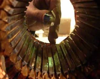 The check should be short-term and be careful the ball can fly out!
I've been an electrician for a long time and I check for turn-to-turn shorts, unless a 380V motor starts to get very hot after 15-30 minutes of operation. But before disassembling, with the motor turned on, I check the amount of current it consumes in all three phases. It should be the same with a slight correction for measurement errors.
Related content:

We advise you to read
 Psychological characteristics of children in adolescence
 Transferring a child to another school - the procedure and necessary documents Whether to transfer a child to another school
, diagnosis, treatment Treatment of urogenital chlamydia") Chlamydia urogenital - description, causes, symptoms (signs), diagnosis, treatment Treatment of urogenital chlamydia
Chlamydia urogenital - description, causes, symptoms (signs), diagnosis, treatment Treatment of urogenital chlamydia The benefits and significance of hydroamino acid threonine for the human body L threonine what

