A. P. Kashkarov, St. Petersburg
For the manufacture of transformers and chokes, special winding wires are used. The main types of such wires of domestic and foreign production are described in this article.
Domestic winding wires
Winding wires in enamel insulation based on high-strength synthetic varnishes with a temperature index (TI) in the range of 105 ... 200 are most widely used. TI is understood as the temperature of the wire at which its useful life is at least 20,000 hours.
Copper enameled wires with insulation based on oil varnishes (PEL) are produced with a core diameter of 0.002 ... 2.5 mm. Such wires have high electrical insulation characteristics, which are practically independent of the external influence of elevated temperatures and humidity.
PEL type wires are characterized by a greater dependence on the external influence of solvents, compared to wires with insulation based on synthetic varnishes. The PEL winding wire can be distinguished from others even by its external sign - the enamel coating is close to black in color.
Copper wires of types PEV-1 and PEV-2 (produced with a core diameter of 0.02 ... 2.5 mm) have polyvinyl acetate insulation and are distinguished by a golden color. Copper wires of types PEM-1 and PEM-2 (with the same diameter as PEV) and rectangular copper conductors PEMP (section 1.4 ... 20 mm2) have varnished insulation on polyvinylformal varnish. Index "2" in the corresponding designation of PEV and PEM wires characterizes two-layer insulation (increased thickness).
PEVT-1 and PEVT-2 are enameled wires with a temperature index of 120 (diameter 0.05 ... 1.6 mm), they have insulation based on polyurethane varnish. These wires are easy to install. When soldering, it is not necessary to strip the varnished insulation and apply fluxes. Enough ordinary solder brand POS-61 (or similar) and rosin.
Enamelled wires with insulation based on polyesteramide PET-155 have TI equal to 155. They are produced with cores not only of round cross-section (diameter), but also of rectangular (PETP) type with a conductor diameter of 1.6-1 1.2 mm2. In terms of their parameters, PET wires are close to the PEVT type wires discussed above, but have a higher resistance to heat and thermal shock. Therefore, winding wires of types PEVT and PET, PETP can be especially often found in powerful transformers, including transformers for welding.
Domestic high-frequency winding wires
On the high frequencies stranded enameled winding wires (litz wires) of the LESHO type in silk single-layer insulation or LESHD - fv double silk insulation are used. Such wires consist of a bundle of copper enameled wires with a diameter of 0.05 ... 0.1 mm and are used for inductors (and chokes). In high-frequency wires of the LESHO, LESHD, PELO, LELD, DEP, LEPKO types, the cores are twisted from individual enameled wires to reduce losses from the surface effect (proximity effect). Table No. 1 shows the diameters of widely used high-frequency winding wires of domestic production. For odd numbers, the wire diameter is approximately equal to half the sum of the diameters of two adjacent (even) numbers. 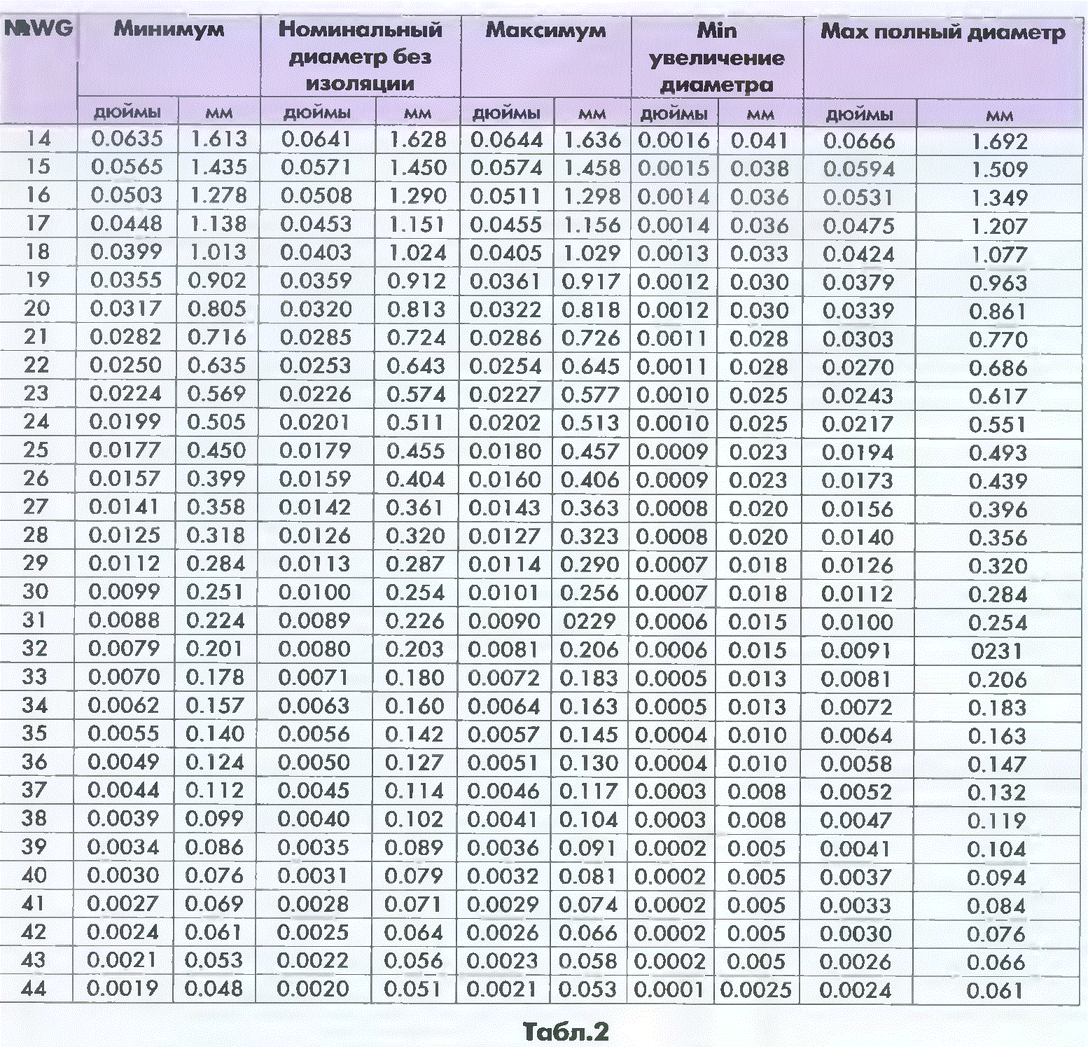
Designation of popular foreign winding wires
In the US and UK, the designation of the diameters of the winding wires is written with the words wire size (wire size).
For example, in the USA the system
American Wire Gauge (AWG). Also sometimes in the US they use the B&S system, and in the UK they use the Standard Wire Gauge (SWG). Table 2 and Table 3 show the diameters of widely used types of winding wires according to AWG and SWG standards.
Permissible load for conductors 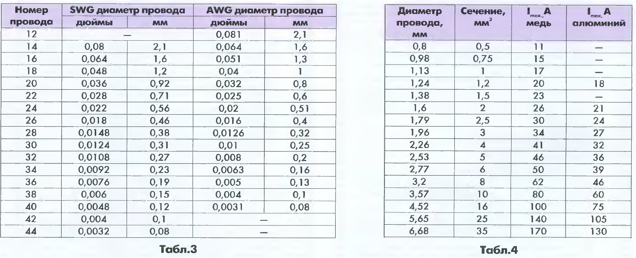
The maximum allowable current that can be passed through the wires without worrying about fire or contact failure is determined in accordance with Table 4. The maximum heating of rubber or plastic (as well as their combinations or derivatives) insulation of wires should not exceed +50 degrees. The duration of safe exposure depends on this temperature parameter.
per conductor maximum admissible current(I max A in Table 4)
Magazine "Electrician"
Almost main question all radio amateurs How can a transformer be wound? We already know the simplest methods for calculating transformers (who has forgotten, you can look here), but the most important thing is where to get wire? Yes, and exactly what kind of wire is needed to wind the transformer?
Where did, for example, wire marks PELSHO, PELBO and others that were sold in Soviet times in sets and reels? The first of the above wires is required for winding loop coils for low-frequency ranges, chokes, transformers on ferrite rings, etc. The second is necessary for winding windings powerful power transformers.
After all, the advantage of such wires over conventional ones (lacquered) is great.
First of all, this is the winding pitch created by the braiding of the wire. In powerful network transformers, the voltage difference in the windings between adjacent conductors is 1 V or more, thin varnish insulation, when heated and vibrated at the network frequency, is gradually erased from friction between vibrating turns and crumbles. As a result, there are interturn short circuits.
For illustration, I will give simple calculation. Let's take transformer iron with core section area S=10 cm2. Based on a simple estimate, Pr=S2, we determine that the overall power of the future transformer will be approximately 100 watts. Number of turns per 1 V:
w1 \u003d 50 / S \u003d 50 / 10 \u003d 5 (vit. / V),
Accordingly, the interturn voltage:
U1=1/5=0.2(V)
If the transformer iron is with a cross-sectional area S=50 cm2, the overall power of the transformer in this case is Pg=2500 W, and w1=50/50=1 (vit./V), which is equal to the interturn voltage in the windings. With a further increase in the overall power, the turn-to-turn voltage increases, the risk of insulation breakdown increases, and the reliability of the transformer naturally decreases.
How to get out of this situation? It should be remembered that the wires are not only winding. To wind the transformer, you can use a mounting wire in fluoroplastic insulation (MGTF) with a cross section corresponding to the required current. Since in such wires it is customary to indicate not the diameter, but the cross section (along the core), then you should use the conversion formula
d=2 (Sp/3.14)^0.5
where Sp - wire section, mm2; d - wire diameter, mm. For example, the MGTF-0.35 wire has d-0.66 mm. The wire diameter, depending on the required current I (A), is determined by the formula:
d = 0.8 I0.5.
Then the current in the winding wire:
I \u003d (d / 0.8) ^ 2 \u003d 0.68 (A)
The excellent quality of the insulation of MGTF wires makes it possible to do without winding ![]() interlayer gaskets, and its heat resistance allows winding transformers operating at elevated temperatures (fluoroplastic insulation does not melt or char).
interlayer gaskets, and its heat resistance allows winding transformers operating at elevated temperatures (fluoroplastic insulation does not melt or char).
Sometimes for balanced circuits it is required to wind a transformer with strictly identical windings.
This can be done by taking a flat cable as winding wires, for example, used in computer connecting cables. Having separated the required number of conductors from the cable, they wind the winding with them, which is then used as several identical ones, isolated from each other. The insulation of the flat cable is sufficiently thermally stable.
For high currents secondary windings power supply transformers are wound with sufficiently thick wires and tires. This work, it must be said, requires not only material (monetary), but also physical costs, since it is necessary to bend the elastic copper bus (wire) to tightness, trying to lay it coil to coil.
As an alternative to winding wire, I suggest using an acoustic cord, which is usuallyconnect the amplifier to the speakers. The acoustic cord has a large cross section of the core and. being double, ensures that the half-windings are identical for a full-wave rectifier with a mid-point. Little attention is paid to the identity of these half-windings, and this entails an increase in the background to which modern high-quality equipment is so sensitive.
The identity of the windings can be ensured in another way, for example, by winding them microphone cord(with a stereo cord we get three windings). In this way it is possible to wind the winding(s) with an electrostatic screen. To do this, the shielding braid of the microphone cord is connected (on one side) to the common wire.
Coaxial cable, due to the large difference in the cross sections of the inner core and braid, is not very suitable for symmetrical windings, but can be used as winding wire when the screen and the inner core are interconnected. The inner core of the cable can also be used for measuring purposes.
In all cases, one should not forget about the thermal stability of the wire insulation. The increased relative lacquer thickness of the wire insulation, on the one hand, reduces the number of winding turns that can be placed in the window of the transformer core, on the other hand, makes the use of interlayer insulation (up to interwinding insulation) unnecessary, which speeds up the manufacture of the transformer, and with heat-resistant wire insulation it increases reliability transformers.
V. BESEDIN, Tyumen.
Winding a transformer with your own hands is in itself a simple procedure, but it requires significant preparatory work. Some people involved in the manufacture of various radio equipment or power tools have a need for transformers for specific needs. Since it is not always possible to purchase a specific transformer for specific cases, many wind them on their own. Those who make a transformer for the first time with their own hands often cannot solve the problems associated with the correct calculation, selection of all parts and winding technology. It is important to understand that assembling and winding a step-up transformer and a step-down transformer are not the same thing.
The winding of the toroidal device is also significantly different. Since most radio amateurs or craftsmen who need to create a transforming device for the needs of their power equipment do not always have the appropriate knowledge and skills on how to make a transforming device, therefore this material is aimed specifically at this category of people.
Preparation for winding

The first step is to make the correct calculation of the transformer. Calculate the load on the transformer. It is calculated by summing all connected devices (motors, transmitters, etc.) that will be powered by the transformer. For example, a radio station has 3 channels with a power of 15, 10 and 15 watts. The total power will be equal to 15 + 10 + 15 = 40 watts. Next, take the correction for the efficiency of the circuit. So most transmitters have an efficiency of about 70% (more precisely, it will be in the description of a specific circuit), so such an object should be powered not with 40 W, but with 40 / 0.7 = 57.15 W. It is worth noting that the transformer also has its own efficiency. Usually transformer efficiency is 95-97%, but you should take the correction for homemade and take the efficiency equal to 85-90% (selected independently). Thus, the required power increases: 57.15 / 0.9 = 63.5 watts. Standard transformers of this power weigh about 1.2-1.5 kg.
Next, they are determined with input and output voltages. For example, let's take a step-down transformer with voltages of 220 V input and 12 V output, the frequency is standard (50 Hz). Determine the number of turns. So, on one winding their number is 220 * 0.73 = 161 turns (rounded up to an integer), and on the bottom 12 * 0.73 = 9 turns.
After determining the number of turns, proceed to determine the diameter of the wire. To do this, you need to know the flowing current and current density. For installations up to 1 kW, the current density is chosen in the range of 1.5 - 3 A / mm 2, the current itself is approximately calculated based on the power. So, the maximum current for the selected example will be about 0.5-1.5 A. Since the transformer will operate with a maximum of 100 W load with natural air cooling, the current density is assumed to be about 2 A / mm 2. Based on these data, we determine the wire cross section 1/2 = 0.5 mm 2. In principle, the cross section is sufficient to select a conductor, but sometimes a diameter is also required. Since the cross section is found according to the formula pd 2 / 2, the diameter is equal to the root of 2 * 0.5 / 3.14 = 0.56 mm.
In the same way, the cross section and diameter of the second winding are found (or, if there are more of them, then all the others).
Winding materials
Winding a transformer requires careful selection of the materials used. So, almost every detail is important. You will need:
- Transformer frame. It is necessary to isolate the core from the windings, it also holds the coils of the windings. Its manufacture is carried out from a durable dielectric material, which must necessarily be quite thin so as not to take up space in the intervals ("window") of the core. Often, special cardboard, textolite, fibers, etc. are used for these purposes. It should have a minimum thickness of 0.5 m, and a maximum of 2 mm. The frame must be glued; for this, ordinary joinery adhesives (nitro-adhesives) are used. The shapes and dimensions of the frames are determined by the shapes and dimensions of the core. In this case, the height of the frame should be slightly greater than the height of the plates (winding height). To determine its dimensions, it is necessary to make preliminary measurements of the plates and estimate approximately the height of the winding.
- Core. A magnetic core is used as a core. Stripped transformer plates are best suited for this, since they are made of special alloys and are already designed for a certain number of turns. The most common form of the magnetic circuit resembles the letter "Ш". At the same time, it can be cut from various blanks available. To determine the dimensions, it is necessary to pre-wind the wires of the windings. To the winding, which has the largest number of turns, determine the length and width of the core plates. For this, the length of the winding is taken + 2-5 cm, and the width of the winding is + 1-3 cm. Thus, an approximate determination of the size of the core occurs.
- The wire. Here the winding and wires for the leads are considered. The best choice for winding coils of a transforming device are considered copper wires with enamel insulation (type "PEL" / "PE"), these wires are enough for winding not only transformers for amateur radio needs, but also for power transformers (for example, for welding). They have a wide selection of sections, which allows you to purchase the wire of the desired section. The wires that come out of the coils must have a larger cross section and be insulated with PVC or rubber. Often used wires of the "PV" series with a cross section of 0.5 mm 2. It is recommended to take on the output wires with insulation different colors(so that there is no confusion when connecting).
- Insulating pads. They are necessary to increase the insulation of the winding wire. Usually thick and thin paper is used as spacers (tracing paper is well suited), which is laid between rows. In this case, the paper must be complete, without breaks and punctures. Also, windings are wrapped with such paper after they are all ready.
Ways to speed up the process
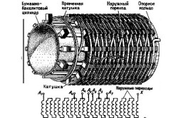
Many radio amateurs often have special primitive devices for winding windings. Example: a primitive winding machine is a table (often a stand) on which bars with a rotating longitudinal axis are installed. The length of the axis is chosen 1.5-2 times the length of the frame of the coils of the transforming device (the maximum length is taken), at one of the exits from the bars, the axis must have a handle for rotation.
A reel frame is put on the axis, which is stopped on both sides by restrictive pins (they prevent the frame from moving along the axis).
Next, a winding wire is attached to the coil from one of the ends and winding is carried out by rotating the axis knob. Such a primitive design will significantly speed up the winding of the windings and make it more accurate.
Winding process
The winding of the transformer consists in winding the windings. To do this, the wire that is planned to be used for windings is wound tightly on any coil (to simplify the process). Further, the coil itself is installed either on the device indicated above, or wound "manually" (this is difficult and inconvenient). After that, the end of the winding wire is fixed on the winding coil, to which the lead wire is soldered (this can be done both at the beginning and at the end of the operation). Then the coil starts to rotate.
In this case, the coil should not move anywhere, and the wire should have a strong tension for tight laying.
The winding of the turns of wire should be carried out longitudinally so that the turns fit together as tightly as possible. After the first row of turns has been wound along the length, it is wrapped with special insulating paper in several layers, after which the next row of turns is wound. In this case, the rows should fit snugly against each other.
In the process of winding, you should control the number of turns and stop after winding the desired amount. It is important that full turns are counted, not taking into account the consumption of wire (i.e. the second row of turns requires more wire, but the number of turns is wound).
The windings of low power transformers are usually made with round wire. Currently, there are a large number of brands of winding wires. Wires are made with fibrous, enamel and combined enamel-fiber insulation. To designate brands of wires accepted letter designations. The first letter for all types of insulation P (wire). Fibrous insulation has the designation: B - cotton yarn, W - natural silk. ShK or K - rayon (kapron), C - fiberglass, A - asbestos fiber. The next letter O or D indicates one or two layers of insulation. Wires in enamel insulation are designated with the letter E. Combined insulation consists of enamel insulation, additionally covered with fibrous insulation. In the manufacture of low power transformers, wires in enamel insulation are mainly used. The enamel layer must have a continuous and even surface and have sufficient mechanical strength and elasticity. The enamel layer should not crack or detach from copper when winding. High mechanical strength and increased heat resistance of vinyl-flex insulation, which makes it possible to significantly reduce the number of interlayer spacers, increase thermal conductivity and allowable current density, provided wires of grades PEV-1, PEV-2, PETV, etc. wide application in the manufacture of low power transformers. At present, wires insulated with cotton yarn and paper tape grades PBD, PBOO, PBBO, etc. are widely used in power transformers medium and high power and in instrument transformers (voltage and current) operating in oil. Enameled wires are not used in such transformers. For transformers open type, power for voltages up to 500 V and current transformers up to 6-10 kV are used as windings with PBD wire, and combined with enamel and cotton coating, but at the same time, transformer windings must be impregnated or compounded. For welding, load and other similar transformers and devices, glass-insulated wires should be used. Wires in asbestos insulation are also used, but their electrical properties and strength are much worse, the insulation thickness is increased, which reduces the thermal conductivity of the windings. In addition, they are hygroscopic. For the above works, rectangular wires are sometimes used. The latter are carried out by brands: PBD, PBOO, PSD, PSDK, PDA. Thickness and insulation are within round wire grades - or upper limits - or slightly higher. Of the indicated brands of wires for low power transformers, PELSHO wire is used for windings on overvoltages(for example, in windings high voltage oscilloscope and in other cases). PELSHO (and PELBO) is expedient to be used for biscuit winding of small transformers impregnated with gluing compounds, due to the high adhesion of fibrous materials with most gluing compounds. PESHO wire is widely used in the circuits of radio receivers, but the suitability of a particular impregnation (and other materials) is determined by the loss factor, which is not essential for a frequency of 50 Hz. In cases where one of the main requirements for equipment (transformer) is reliability, the winding must be impregnated with some kind of varnish or compound. A significant increase in reliability is facilitated by lighter operating modes of the windings and the use of materials with a temperature in terms of heat resistance 1-2 classes higher than the operating temperature of the winding. In cases where the transformer can operate in a forced mode, the winding must be impregnated, since this increases the thermal conductivity and heat resistance due to a more uniform temperature in the thickness of the winding. In the forced mode, it is permissible to increase the heating of the transformer by 10-12 ° C above the temperature of this class. In this case, the aging process of the material is accelerated by approximately (on average) 2 times. It should be noted that the permissible temperatures for wires PEL, PEL 100-105 ° C, PET 125 ° C, PEV-1, PEV-2 110 ° C. For transformers that are subject to reliability requirements, forced modes are unacceptable. The given scale of heat resistance classes is accepted both in Russia and in a number of foreign countries. The lower limit of permissible temperatures for enamel wires is 60 ° C. At this temperature, the enamel should not crack and lag behind copper.


