In the second article on repair Samsung TVs manufactured by "Telebalt" LLC, the authors share their experience of pre-sale and warranty repair of TVs made on the KS7A(C), KS9A(B) chassis. In addition, the authors used forum materials on the MONITOR website (http://monitor.net.ru/forum/index.php).
Samsung TVs based on KS7A(C) and KS9A(B) chassis
In the magazine "Repair & Service" (see), articles describing TVs produced on the KS7A (P) and KS9A (P) chassis were previously published. fundamental wiring diagram the chassis, if necessary, can be taken from the specified source. The basic composition of the chassis KS7A (C) and KS9A (B) is presented in the table.
Table. Basic composition of the KS7A(C) and KS9A(B) chassis
| No. p / p | Name | Position number (chassis KS7A) | Element type (chassis KS7A) | Element type Positional (KS7С chassis) number (KS9х chassis) | Element Type (KS9A Chassis) |
|
| Single Chip (UOC) Processor | TDA9381/N3/3/1642 CG5581 35 63408480 SPM 802EEN6* |
|||||
| Quartz resonator | ||||||
| UPS controller | KA5Q0765RT with PS2561 optocoupler (Samsung 15K2MJQ - without it) |
|||||
| Personnel scan | ||||||
| TDA8944J (TDA8943SF) |
||||||
| Line scanning | ||||||
| video amplifier | ||||||
| FSA38032M (AA26-00238A (25-0218A)) TDQ-61/125S (AA40-10007A) AA40-00077A |
||||||
* - the full marking of the microcircuit is shown, applied on its case, the first (microcircuit type and firmware code) and fourth (TV model) lines of marking are relevant, as they allow you to judge the TV model in which it is installed, as well as resolve issues of replacing the UOC.
Typical malfunctions of SAMSUNG TVs on the KS7A (C) chassis
TV does not switch from standby to work
An additional check revealed that all output voltages of the power supply are normal. The reason is the ICV201 microcontroller (VCT49X3FPYF1000, firmware 1703) is faulty.
After turning on, a click is heard and the TV switches to protection mode
A similar defect is caused by an interturn breakdown in the OS coils.
The TV does not switch from standby to working mode, after trying to turn on the TV switches to protection mode, while the LED indicator flashes, extraneous noise is heard from TDKS
The horizontal scan supply voltage is 150 V. The reason is the breakdown of the Zener diode DZ807.
The TV turns on, but there is no characteristic noise image (snow) on the screen, OSD is present
The supply voltage is normal, reprogramming the EEPROM did not bring any result. The reason is the ICV201 microcontroller is faulty.
The raster has an inversion from the bottom vertically
Faulty zener diode DZ305 and capacitor C409. In addition, in such a case, the resistor R413 (0.6 ... 1.0 Ohm) may fail.
"Rainbow" stains are visible on the screen, after trying to turn on the TV switches to protection mode
With an increase in the accelerating voltage (with the Screen regulator on the TDKS), the divorces become brighter, OX lines appear, after which the TV switches to protection mode. The manifestation of this defect is the same as in the absence of one of the supply voltages of the KR microcircuit (beam outside the screen). The cause of the defect is a break in the conductor on the board to the capacitor CV919 in the +5 V circuit.
In the lower part of the image, there is a raster inversion, while the vertical size is adjusted normally
The reason is an open resistor R303.
No channel tuning
Supply voltage is normal. Replacing the tuner, reprogramming the EEPROM did not fix the problem. The reason is a malfunction of QV904 (STK7000 630) in the SCL-SDA circuit.
The TV is working fine, but a high-frequency "beep" is heard from the chassis
The reason is related to poor-quality soldering of the capacitor C824.
Image phase shift, a wide band from the edge, the image itself shows the overlap of the missing part of the image (horizontal inversion)
Open diode DZ403.
The TV turns on, but the raster is compressed horizontally, OX lines are visible
The reason is a break in the diode D406 and capacitor C411 (470 pF) in the ABL circuit.
The image shows wavy lines, the intensity of which increases with warming up. After a while, the transistor SR Q401 fails
The so-called "thermal" breakdown of the transistor occurs when the resistance between the collector and emitter terminals of the transistor is zero. Possible reasons:
Faulty transformer 1401T (part number AA26-50001M);
Open resistor R817.
In standby mode, the UPS turns off - the LED on the front panel goes out
The UPS is made on the IC801S controller type STR-X6757. With a mains supply voltage of 170...180 V, the defect does not appear. At the rated supply voltage, if you do not turn on the TV in standby mode for 5 ... 10 seconds, it will turn itself off. If you have time to turn on the TV in the operating mode during this time, then it will work normally. The cause of the defect is a leak in the Zener diode DZ813 (9.1 V).
Note.
1. The voltage B + in the operating mode is 130 V, and in the standby mode - 107 V, the voltage at the pin. 4IC801S is 20.8V and 16.9V respectively.
2. STR-X6757S chip can be replaced with STR-X6750B.
Typical malfunctions of Samsung TVs on the KS9A(B) chassis
Malfunctions of the power supply and horizontal scanning
TV does not turn on
Possible reasons:
Broken diode D805;
Breakdown of the capacitor C804 (when connected to the output of the UPS, instead of a horizontal scan of an incandescent lamp, it does not start).
TV does not switch from standby to work
Possible reasons:
Open throttle L403;
In position Q901, the transistor KSC815-Y is mistakenly installed instead of KSA539-Y.
TV does not switch from the remote control from standby to work, the UPS is working
Faulty photodetector RM901.
TV does not turn on, no UPS output voltage
The case of the IC801S controller (KA5Q0765R) is destroyed. After replacing the microcircuit and three zener diodes in the "strapping", the UPS does not turn on - only attempts to start are observed. The reason is the "leakage" in the capacitor C806 (4700 pF x 50 V) connected to the pin. 5 IC801S - its "leakage" resistance was 800 ohms. In some circuits, it is designated as C805 (3900 pF x 100 V).
TV is transferred from DR to RR, while a strong hum is heard in the speakers
The client associated the occurrence of a malfunction with a thunderstorm that preceded it. The UPS was tested offline using an incandescent lamp. When a 220 V/60 W lamp is connected to it instead of a horizontal scan, the voltage at the UPS output changes in the range of 135 ... 162 V at a standard of 125 V. The LED blinks constantly. The reason is the "leakage" (in the continuity mode - about 500 ohms) between the pin. 3 and 4 (phototransistor) of PC801S optocoupler (PC2561), which can be replaced by PC817.
Note. Since the 5Q0765RT power controller is used in the UPS of other SAMSUNG TV chassis (KS1A, S16B), all recommendations and typical malfunctions discussed in are valid when repairing it.
TV does not turn on, standby LED does not light, UPS is OK
After installing a "clean" EEPROM chip, replacing the DZ901 (zener diode in the EEPROM power supply circuit with a stabilization voltage of 4.7 V), the TV turned on, an image appeared, but there was no sound. In order to restore the sound, it is necessary to adjust the AUDIO options in the service mode (see ) AUDIO: NICAM; 2ND SIF: ON (depending on chassis configuration).
TV does not always switch from standby to work
The TV sometimes turns on and works normally, but if you switch it to standby mode with the remote control, then you can turn it on again only after disconnecting the device from the network. When you turn it on again, the situation repeats. After turning on the TV with the network button, it remains in standby mode, and when you press the P + button, the TV exits it, but does not work. +11.5V voltage is low to 9.35V, other UPS voltages are normal. The TV circuit is slightly different from the basic circuit of the KS9B chassis: there is no Q802 transistor (Power switch). The controlled stabilizer IC802 (KA7632) is used to switch the "working-duty" modes.
The reason for this malfunction is the Zener diode DZ808 (6.2 V), it has an underestimated stabilization voltage.
When transferring the TV from standby to working, one attempt out of several fails
There is no system, most often the TV can turn on after repeated pressing of the ON / OFF button, after which it works fine, the response to the local keyboard keys is adequate. From the front panel, the TV never turns on, only with the remote control or as described above.
All supply voltages are normal. The TV circuit differs from the KS9B chassis in the same way as in the previous case. The electrolytic capacitors and zener diodes in the "strapping" IC802, the KA7632 itself, the zener diode DZ808 (6.2 V), the UOC processor, the quartz resonator, the photodetector were replaced. On the I 2 C bus, the signal levels are normal.
Cause of malfunction - defective non-polar capacitor C220 (0.47uF x 63V) orange color, connected to the pin. 64 UOC processors. Because of him violated normal work RESET node. The capacitance meter showed full compliance with the nominal value, and in the resistance test mode, the multimeter showed a "leakage" of about 110 kOhm, in addition, the dependence of the "leakage" on the mechanical impact on the capacitor terminals (85 ... 200 kOhm) was noticed. A similar failure of the indicated type of capacitors is typical for this chassis.
TV does not switch from standby to working mode, UOC processor does not initialize EEPROM
After programming the EEPROM with a known working firmware, the TV started working, but when you try to enter the service mode, the TV switches to standby mode and remains in it. The UOC processor needs to be replaced.
When you turn on the TV, it briefly appears high voltage and it switches to standby mode
All supply voltages are normal, the POWER signal is coming from the UOC processor. The reason is that the UOC processor IC201S is faulty.
TV does not turn on from standby mode
When measuring voltages at the outputs of IC802 (KA7632), instead of 8 V - 6V, and instead of 11.5 V - 8 V. The reason for the failure is a malfunction of the Zener diode DZ808 (6.2 V) (in some models - DZ804 (7.5V)), connected anode to the pin. 1 optocoupler PC801S.
No raster, judging by the sound, the channels are switching
On the output 49 IC201S no voltage, when accelerating voltage is added with the Screen regulator, a raster with OX lines appears. Faulty UOC processor IC201S.
LED indicator does not light up
Poor soldering of one of the outputs of the transistor Q901;
Faulty or not installed transistor Q901 (KSA539-Y).
Frame scan faults
The vertical centering is broken and it is not adjustable in the service menu
Poor soldering of the terminals of the capacitor C309 or its malfunction.
Malfunctions caused by the distortion of information in the EEPROM or its malfunction
- There is no setting for channels.
- There is no sound when the TV is working from the antenna (from the tuner). In the LF input mode, the TV works fine.
- There is no soundtrack.
- When test signals from a DVD player are input to the LF input in the Screen setting mode, the brightness of the image does not change.
- There is no color when applying test signals from a DVD player to the LF input.
- Station settings are not remembered.
In all these cases, the EEPROM chip is first flashed, and then, if there is no result, it is replaced.
Faults associated with the lack of sound
No sound
Faulty UOC processor IC201S;
Faulty IC602 chip.
Poor soldering of the terminals of the capacitor C603.
The sound disappears, when switching from program to program - a delay of up to 7 seconds
After 2-3 hours of operation, the soundtrack disappears, while all channels are initialized as STEREO. When switching from program to program, there is a delay of a few seconds. All nutrition is normal. The reasons:
Faulty sound processor ICS01 (MSP3400G);
Faulty reset chip ICS02.
Faults associated with the lack of reception, the presence of interference
No reception
Voltage +5.1 V (tuner power circuit) is missing. The reason is that the resistor R413 is not installed (elements L102 and R413 (22 ohms) are not indicated in the diagram).
Tuner defective.
No channel tuning
The reason is that the capacitors C208, C210 are faulty (the device is defined as serviceable). C210 is in the IF signal processing circuits, and C208 is in the power circuit.
Interference is observed on the screen, when the degaussing loop is turned off, the interference disappears
Capacitor C830 is not installed (faulty) (one of two).
Noise in the image
AGC works fine, replacing the tuner and processor did not give anything. The reason is poor-quality soldering of one of the terminals of the capacitor C213.
There are no visual changes when adjusting AGC in service mode
Tuner defective.
No channel tuning
Open capacitor C210.
Geometric raster distortion
Flipping the image at the top of the raster
Possible reasons:
Not soldered (or open) resistor R315 in the raster correction circuit;
The polarity of CR01S is reversed (100 uF x 50 V).
Vertical violation at the top of the raster
In position C303, instead of a 180 pF capacitor, a 560 pF capacitor was mistakenly installed.
Horizontal raster non-linearity
Causes - the LR401 (402) inductor is incorrectly soldered (violation of the winding phasing) or the R402 resistor of a different rating is mistakenly installed.
Barrel raster distortion
Removing the CR409S capacitor from the circuit was not enough. The defect was eliminated by derating the CR410S from 6800 pF to 5500 pF.
The horizontal size does not correspond to the universal test table (TU). Faulty capacitor CR409S.
Flip horizontally
Poor soldering of the leads of the CR405 capacitor.
Horizontal image non-linearity
The reason is that when mounting the chassis, the leads R401 and R403 were shorted with solder.
Raster "breathing" is observed
Poor quality soldering 5 UPS controllers (KA5Q0765R).
There is a "twist" on the top of the image, there is no frame synchronization when switching channels. AV input image is normal
Faulty UOC processor.
Other malfunctions of the KS9A(B) chassis
The TV turns on, the noise characteristic of the absence of a signal at the antenna input is visible on the screen, then the image darkens, the filament voltage on the kinescope is present, and then disappears after a while
Checking the information in the EEPROM showed that it was distorted. After rewriting the memory chip, tuning to channels became possible, otherwise the behavior of the TV did not change. The reason is that the UOC processor IC201S is faulty.
The image shows "knocking out" lines
Faulty UOC processor IC201S.
During prolonged TV operation, a non-periodic horizontal synchronization failure occurs; when an antenna is connected, the raster size may change
Poor soldering of the terminals of the Q201 transistor in the ETL circuit (ABL);
Transistor Q201 is faulty (no deviations were detected by an ohmmeter);
Distortion of information in EEPROM;
There is no jumper in position R422, it must be installed.
Red raster with OX lines
Break in the wire in the loop from the main board to pin 1 of the CN501 connector of the kinescope board.
Noise is heard when TV is turned on, mute does not work
Poor soldering (terminals of transistor Q903 closed with a solder jumper).
Missing color in SECAM color system
Faulty capacitor C233 (leak).
Missing color in PAL color system
Capacitor C909 not installed (or open);
Open capacitor C908.
The image in PAL and SECAM shows color repetitions (dark and light stripes)
Poor soldering of the middle terminals of the Z202 and Z203 band pass filters.
Moire on the image in PAL and SECAM color systems
Capacitor C217 not installed (or open).
Moire on the image (present on all channels)
Capacitor C213 not installed (or open).
There is a dark transparent strip on the left side of the screen, the geometry in this part of the screen is distorted
Open capacitor CR405, which leads to the burnout of the resistor R408.
On the left side of the screen, a dark stripe is observed, shifted relative to the edge of the screen by 1.5 ... 2 cm
Not installed (or open) capacitor CR404S (680 pF x 2 kV).
In the LF input mode, the TV works normally, but in the auto search mode, TV channels are not remembered; when memorizing in manual mode, noise interference is observed on the screen, the image is periodically disrupted
Poor-quality soldering on the chassis in the tuner area - the tuner leads and adjacent elements were soldered;
Breakage of the printed conductor from the non-polar electrolytic capacitor C212.
The TV turns on, but there is no noise on the screen, only the OSD is present. As the accelerating voltage increases, a raster with OX lines appears. Cut-off voltage on pin 5 of CN501 is 3.5V instead of 6.8V
Capacitor C420 is not installed in the ABL circuit;
Open resistor R423.
The TV turns on, but there is no noise on the screen, only OSD is present, in the bass input mode the TV works fine
The voltage in the ABL circuit is normal. The reason is the short circuit between the outputs of the band-pass filter Z202.
Moire on the image in the LF input mode
When receiving from the antenna input, the image is without interference, but if a DVD player or satellite tuner is connected through the LF input, distortions in the form of thin curving strips ("wood structure") are visible on the image. The signal sources were checked on another TV, everything is normal. The reason is the lack of a power supply choke LX801S, which was replaced by jumpers when mounting the chassis.
After turning on the TV, there is sound and an image, after a minute the sound remains, and the image disappears. Switching off / on again does not change the situation
When a defect occurs, the RGB signals disappear at the outputs of the UOC processor. It is necessary to enter the service mode (successively press the POWER OFF - DISPLAY - MENU - MUTE - POWER ON keys on the remote control), then press the MUTE key and set the SCREEN ADJUST option on the TV to "OK". The chassis is very inertial and critical to the installation of the Screen.
There is no image and OSD, when you increase Screen - a flare with OX lines appears on the raster
Faulty zener diode DZ503 (9.1 V) connected to pin. 1 IC501 (TDA6107Q) (R-IN signal) on the kinescope board.
Note. Malfunction D502-D504, DZ502-DZ504 on the PC is typical, diodes and zener diodes are determined by an ohmmeter as serviceable, but there is a "leakage" in the operating mode.
Low-frequency hum in the UPS area
Faulty UPS chip (KA5Q0765R).
When turned on, there is a sound that turns into wheezing ("rustling")
Switching the sound system does nothing. Capacitor C601 not installed (or open).
No picture in LF input mode
Faulty (broken) zener diode ZD704.
No picture, sound is on, channels are switching, OSD is present, it may have been preceded by a thunderstorm
When the accelerating voltage was changed, a dull green image and OX lines appeared. Checking by replacing elements D501-D503, TDA6108, adjusting the Screen voltage did not bring any result. The UOC processor turned out to be faulty.
No picture, sound is on, channels change
When the Screen is enlarged a little, a low-contrast image appears, the focus is not, but it is adjustable. The reason is the TDKS type FCA173B (part. No. AA26-00201A) is faulty. It is possible to replace it with TDKS from the chassis KS1A, FSV-14A004C (S), (HR8628), sometimes it may be necessary to increase the capacitor Cox in the collector circuit of the output transistor SR by 500 ... 1000 pF.
The image is pale, blurry, sometimes disappears completely
The raster is increased, the supply voltage of the filament and the second anode are underestimated, the power supply of the video amplifier is also underestimated and is 106 V. The voltages generated by horizontal scanning have not changed much: the power supply of the KR IC is +14 V and -14 V instead of the prescribed 16.5 V. The reason is - faulty TDKS.
Replacing UOC Processors with KS9A Chassis
A fairly common defect on this chassis is no sound, especially after a thunderstorm. This is due to the closure of the pin. 4 UOC processors to ground ("Mute" signal). If you disconnect this pin from the circuit, sound appears. If the UOC processor is not available, then it is enough to solder the Q903 (KSC815-Y) transistor, which forms the control voltage on the pin through the Q905 (KSC815-Y) transistor. 10 IC601 (TDA8944J), which is equivalent to closing the pin. 7, 10, 13 IC604 to "ground" - and the sound will appear. Naturally, the Mute function will not work.
The following defect is often observed: the image from the antenna or AV input is barely visible, while the OSD is normal. The reason for this is a faulty UOC processor.
Chip TDA 9351PS/N3/3/1616 (fourth signature line on the body - SPM-802EE6) is fully interchangeable with the following types:
TDA9351PS/N2/3I1003 (SPM-802EEN4);
TDA9351PS/N2/3I1308 (SPM-802EE5);
TDA9381PS/N3/3/1642 (SPM-802EEN6);
TDA9381PS/N3/3/1677, TDA9381/N2/3I0753 (SPM-802EEN2, used in KS1A chassis);
TDA9381PS/N2/3I1322, TDA 9381PS/N2/3I0974 (SPM-802EEN4).
After replacing the chip in the service menu, turn on the stereo mode, if the chassis option is stereo.
Literature and Internet resources
1. N. Elagin. Adjustment and repair of SAMSUNG TVs on the chassis KS7A(P) REV. 1. "Repair & Service", 2008, No. 1, 2.
2. N. Elagin. TV chassis KS9A(P) from SAMSUNG. Adjustment and repair. "Repair & Service", 2007, No. 3, 4.
3. R. Kornienko, S. Yashin. From the experience of repairing Samsung TVs manufactured by Telebalt LLC. "Repair & Service", 2008, No. 9.
4. Forum site MONITOR. http://monitor.net.ru/forum/index.php.
SAMSUNG TV REPAIR
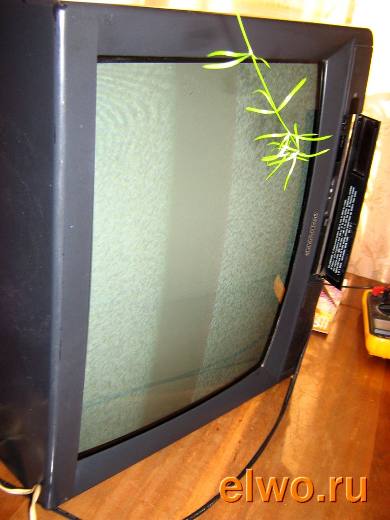
To be honest, when they ask me to fix a CRT TV, even one of the latest models, I go for such a repair with great reluctance. As a rule, such TVs are quite heavy and inconvenient to repair, take at least the dimensions and weight, besides, a good result may turn out to be short-lived. And it startslong trial why and why. But because it is high time to throw out such a box, and not to fool yourself, not people with it.
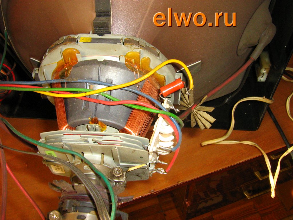
I recently succumbed to such a repair after much persuasion. I carried out preliminary diagnostics immediately from the words of the owner - a thin horizontal strip clearly indicates problems in the vertical scanning unit. Therefore, having learned from a person the model of his Samsung, he immediately downloaded the chassis diagram on the Internet and identified the vertical scanning chip - KA2131.
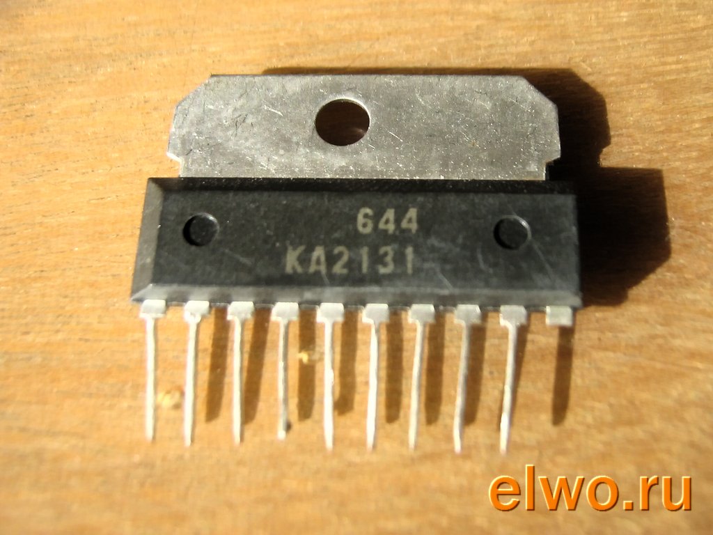
She was captured at the radio bazaar on the way to repairs. We come, we look - a typical large plastic box of fifteen years of age. We open, check KA2131, it is - it burned down. I solder it to a new one and turn it on: everything glows and everything works as it should. I left the TV on for a few minutes while I drink tea with the owner in the kitchen.
I come - the microcircuit is already boiling! I urgently turn it off and try to understand - why? Two reasons are likely: either problems with the power supply of the microcircuit, or a short circuit in the load, in the personnel coil. Since the measurements of the modes with a multimeterdid not reveal any significant deviations from the norm, the personnel coil remains.
To be honest, I have neither the desire nor the opportunity to change, and then also configure it - I make it easier. In the gap of one of the contacts of the coil, I include a 10 ohm resistor a couple of watts. I check again - the microcircuit is almost not heated.
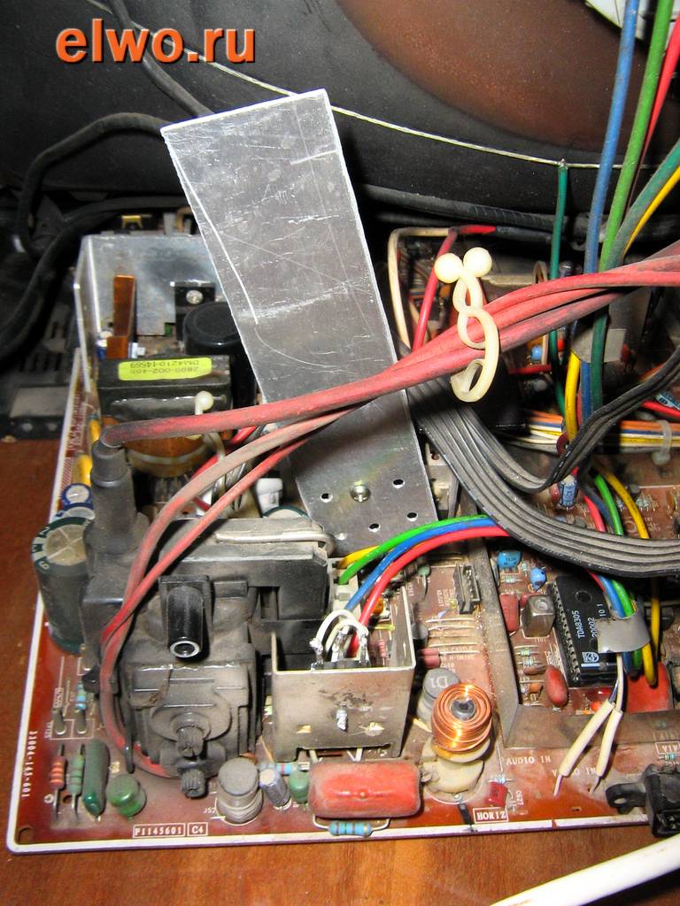
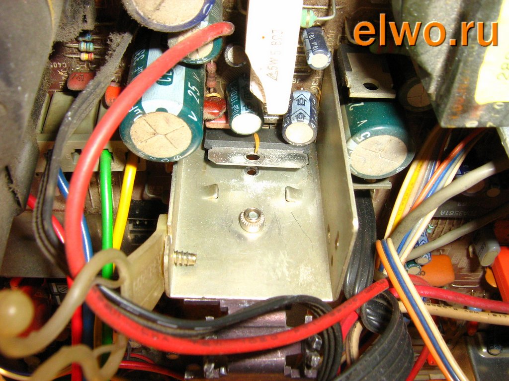
Since "almost" does not suit me, for reliability, I screwed an aluminum plate that came to hand to the vertical scan microcircuit. Now it doesn't get hot at all.
And a small inversion of the beam from the top of the screen was almost completely eliminated by adjusting the trimming resistors of the vertical scan. To consolidate the result, I fasten another piece of aluminum plate to the standard radiator - now it definitely won’t overheat.
You can comment on the repair at
Pavel Potapov
The article discusses in detail the device, adjustment and repair of SAMSUNG TVs assembled on the KS1A (P), REV.1 chassis.
Structural scheme the chassis is shown in fig. one,

BUT circuit diagram- in fig. 2-5. All the main functions for processing a television signal, controlling a television, generating sweep clock signals are implemented on the basis of the TDA9381 microcontroller (UOC - "all in one"). Structurally, the chassis consists of a main board, a kinescope board, and an AV signal input-output board. Some models are equipped with a separate sound processor board.
Main specifications TVs are given in table. 1-4.
![]()
Work description
Power Supply
The power supply unit (Fig. 2) is implemented on the basis of a quasi-resonant converter IC801S (KA5Q0765A) from FAIRCHILD SEMICONDUCTOR. A feature of this microcircuit is the integration in one package of all control circuits and a power MOSFET with a minimum of external elements. The microcircuit provides all the necessary adjustments, control of the output voltage of the power supply, protection against overload, overvoltage and overheating, as well as a restart mode. A temperature sensor is built into the chip. The purpose of the conclusions of KA5Q0765A is given in Table. 5.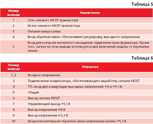
The power supply of the microcircuit (pin 3) in the operating mode of the PSU is carried out from the pin. 6 transformers through the elements D803, R805, R850, and in the initial start mode - through R803, R804, D802. The microcircuit starts working when it reaches the pin. 3 voltages 15±1 V.
When the voltage drops to 9 ± 1 V, the microcircuit turns off. Overheating protection is triggered at a crystal temperature of 160°C. Overvoltage protection is triggered when the pin is reached. 5 potential 11 V. Converter frequency 20±2 kHz. To stabilize the output voltage, the converter is covered by negative feedback. Voltages from secondary windings transformer T801S through a divider on resistors R817, R818 and R822 are fed to the input of the error amplifier IC803, from the output of which the feedback signal through the PC801S optocoupler is fed to pin. 4 IC801S chips.
Two rectified voltages are removed from the I801S transformer:
+125 V - for horizontal scanning;
+13.5 V - for the sound amplifier.
From the voltage +13.5 V using a three-channel precision stabilizer IC802 type KA7632 (Fig. 2), the following voltages are formed: +3.3 V; +5.1 V (V); +5.1 V (C); +8 V.
In addition, IC802 generates a RESET signal to initialize the microcontroller. The POWER signal switches the +8 V and +5.1 V voltage conditioners in the IC802 stabilizer, and also blocks the converter feedback circuit through the Q802 transistor and puts the power supply into idle mode.
The purpose of the KA7632 pins is given in Table. 6.
Line scanning
The horizontal scan generator and synchronization circuit are implemented in the IC201S microcontroller (Fig. 3). Horizontal sync pulses (H-DRIVE) with pin. 33 IC201S through the buffer stage on the transistor Q402 (Fig. 2) and the matching transformer T401 arrive at the output stage, made on the transistor Q401. The load of the output stage is the primary winding of the 9-10 line transformer T444S and the line coils of the deflection system type OSE-1992LL. In addition, horizontal scanning forms the supply voltages of the kinescope - the anode, accelerating, focusing heater, as well as the voltages necessary for the operation of other TV units:±16.5 V - for vertical scanning;
+33 V - for the tuner;
+180 V - for powering video amplifiers on the kinescope board.
To control the current of the kinescope beams, a circuit on the Q201 transistor is used (Fig. 3). The ABL signal, taken from the pin, arrives at its base. 8 line transformer.
The output signal from the emitter of the transistor about the excess of the current of the rays is fed to the pin. 49 microcontroller IC201S, which leads to a decrease in contrast and brightness of the image.
X-ray protection is made on the transistor QR001S (Fig. 2). To control the high voltage of the kinescope, the voltage of the heater (HEATER) is used. When it is exceeded, an X-RAY signal is generated, which is fed to the pin. 36 of the microcontroller and, thereby, the line scan generator is blocked.
Personnel scan
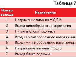
The generator and frame synchronization circuit are implemented in the IC201S microcontroller. The vertical scan output stage is based on the IC301 (LA7840) chip. Sawtooth vertical scan voltage with pin. 21, 22 of the microcontroller is fed to the differential inputs (pins 4 and 5) of the IC301 amplifier (Fig. 2).The pin assignment of the LA7840 chip is shown in Table. 7.
The V-guard signal is used to control the operation of the vertical scanning output stage. The circuit on the transistor Q301 (Fig. 2) converts the pulses of the swap unit into TTL-level signals that enter the microcontroller (pin 49). In the absence of V-guard pulses, horizontal scanning is blocked, thereby preventing the kinescope phosphor from burning through.
Note. The V-guard feature is an option not available on all TVs. Depending on the version of the TV, the V-guard signal can be sent to the pin. 49 or 50 of the microcontroller, or do not apply at all. Switching is carried out by jumpers J144 and J149.
Image processing path
The TV tuner TU01S (Fig. 3) is controlled by a microcontroller via the I2C bus. The IF signal from the IF output of the tuner is fed to the HIC01 preamplifier and, after the SF101S filter, to the balanced input 23, 24 of the IC201S microcontroller. If there is no preamplifier, jumper J109 is installed.microcontroller
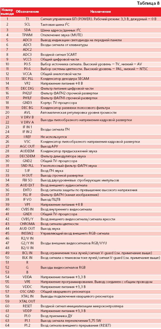
The multifunctional chip TDA9381 from PHILIPS SEMICONDUCTORS combines the functions of processing a television signal and controlling a TV. It is possible to install other controllers of the TDA93XX series with a built-in teletext decoder. The EEPROM IC902 (M24C08) is used to store the TV settings. The microcontroller provides amplification and demodulation of the PHI signal, demodulation of the audio signal (mono), processing of the luminance signal, extraction and decoding of color signals from the PAL / SECAM / NTSC systems, adjustment of brightness, contrast, automatic white balance, beam current limiting, switching of external and internal sources audio and video signals, switching RGB-signals, as well as the formation of signals for vertical and horizontal scanning. The delay lines for luminance and chrominance signals are built into the microcontroller. The block diagram of the microcontroller is shown in fig. 6.The purpose of the TDA9381 pins is given in Table. eight.
After demodulation and amplification, the selected PTsV signal passes to the pin. 38, from where, through the emitter follower, Q202 enters the IF sound rejection filters (FCS), and then to the Q205 base. From the Q205 emitter, the selected video signal is fed to the I / O block board and through C215 to the pin. 40 microcontroller. After processing in the microcontroller, the output RGB signals from the pin. 51-53 are fed to the video amplifier IC501 (TDA6170Q), located on the kinescope board.
Video Amplifier
Amplifier IC501 type TDA6107Q (Fig. 2) provides signal amplification in the 5.5 MHz band up to an amplitude of 60 V. The purpose of the amplifier pins is given in Table. 9.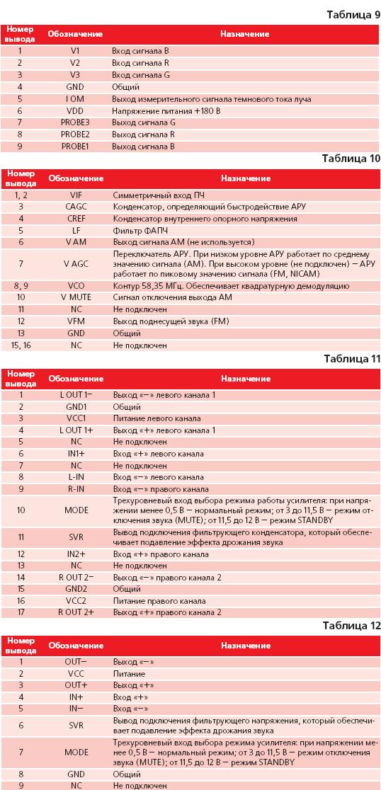
Audio processing path
From the output of the HIC01 preamplifier, the IF signal through the SF102S filter enters the inputs 1, 2 of the IC101 audio demodulator of the U4468B type (Fig. 3). The U4468B is a multi-standard audio pre-processing and decoding processor for digital NICAM and amplitude modulation (AM) signals.The pin assignment of the U4468B is shown in Table. ten.
From the output 12 of IC101, the selected PCR signal is fed to the pin. 32 microcontroller, where it is demodulated. Audio signal output - vyv. 44. Next, the sound signal is fed to the inputs 8, 9 of the power amplifier IC601 type TDA8944J (Fig. 4, 5). The two-channel amplifier is made according to the bridge circuit. Output power: 2x7W into 8 ohms.
The pin assignment of the TDA8944J chip is shown in Table. 11. Amplifier outputs 1, 4 and 14, 17 send sound signals through connectors CN601 and CN603 to dynamic heads.
Options for completing the sound path
In mono versions of TVs, instead of a two-channel power amplifier IC601 (TDA8944J), a single-channel amplifier IC602 (TDA8943SF) is installed. The purpose of the TDA8943SF pins is given in Table. 12. A SCART connector can be installed on the main board (fig. 4). Options for external AV input/output boards (with connectors on the front of the TV) are shown in fig. 5. The boards are connected to the SN701 connector and differ in the number of RCA connectors (mono or stereo) and the presence of a headphone jack.Some TVs are equipped with sound processors of the MSP34XX series (Fig. 4 and 5). They process all analog audio standards as well as the NICAM digital standard. The MSP3411 chip also has a "surround sound" function and can automatically recognize the current standard without resorting to I2C bus communication; The TDA6920 installed with the MSP3405 is a 7 input switcher.
Service mode
Default Setting Mode
This mode is used to set the TV parameters after replacing the IC902 non-volatile memory chip or kinescope.To enter the mode, sequentially press the DISPLAY and FACTORY buttons on the remote control remote control(PDU). If there is no FACTORY button on the remote control, change the button press sequence as follows: STAND BY > DISPLAY > MENU > MUTE > POWER ON.
SERVICE (FACTORY) is displayed on the screen.
To select menu items, use the CHANNEL± buttons, and to change parameters, use the VOLUME± volume buttons. Exit the menu - press the FACTORY or POWER OFF buttons again.
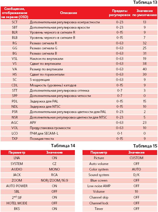
The main adjustment menu (ADJUST) is shown in Table. 13, values of the menu of variables (Option table) - in tab. 14, RESET menu values - in table. fifteen.
TV setup
High voltage controlConnect a kilovoltmeter to the second anode of the kinescope;
turn on the TV, set the brightness and contrast to the middle level;
the voltage at the anode should not exceed 27.5 kV;
changing the values of brightness and contrast from one extreme position to another, make sure that in any case the voltage at the anode does not exceed 27.5 kV.
Video Peak Adjustment
Connect the oscilloscope to the cathode G of the kinescope;a signal of black and white stripes is fed to the input of the TV;
set the STANDARD image mode with the “P” button on the remote control;
using the SCREEN potentiometer on horizontal transformer set the white level to 120 ±2.5 V.
Adjusting the white balance
Warm up the TV for 30 minutes (in OSD White mode). To enter this mode, press the following sequence of buttons: DIPLAY - FACTORY - FACTORY;a test pattern signal is fed to the input of the TV;
in the service mode Factory Service Mode set the value of the parameter SBT (brightness) equal to 3.5±0.5;
adjust the balance in dark areas by changing the values of the BLR and BLB parameters;
set the value of contrast and brightness close to the maximum;
adjust the balance in the highlights by changing the RG, GG and BG values. Beam convergence adjustment
Warm up the TV for 20 minutes;
serve to the input of the TV signal mesh field;
adjust the convergence of the red and blue lines in the center of the screen using a pair of four-pole magnets on the kinescope. By changing the angle between the magnets, the red and blue vertical lines are brought together. By rotating the magnets around the axis and maintaining the angle between them, the red and blue horizontal lines are brought together;
adjust the convergence of the purple and green lines with a pair of six-pole magnets. By changing the angle between the magnets, the vertical lines are brought together, by rotating the magnets, the horizontal lines are brought together.
Note. Magnets are located on the neck of the kinescope in the following sequence (in the direction from the kinescope panel to the screen):
six-pole magnets for mixing green and purple lines;
four-pole magnets for mixing red and blue lines;
bipolar magnets of color purity.
Possible malfunctions and ways to eliminate them
The TV does not turn on, the mains fuse blows
They check the health of the elements of the surge protector (VX801S, CX801S, RX801S), the SW801S switch, the kinescope demagnetization circuit, the rectifier (D801S-D804S, C801), the windings 1-4 of the transformer T801S, C806, the IC801S microcircuit (output stage).The TV does not turn on, the mains fuse is good, POWER indicator does not glow
Check the presence of +300 V voltage on the capacitor C801 and pin. 1 IC801S. If there is no voltage, check the serviceability of the elements of the mains filter, switch, diode bridge, windings 1-4 of the T801S transformer. Check the presence of supply voltage at the pin. 3 IC801S (IC trigger voltage is 15±1V). In the absence of voltage, the serviceability of resistors R803, R804, R806, capacitor C802, diode D802 and zener diode DZ803 is checked. If the supply voltage is normal, check the feedback circuit DZ804, PC801S, C804, R840, DZ802, C803, R843, DZ801 and the synchronization circuit D804, R831, C805, R808, DZ805. If the failed element is not found, replace the IC801S.POWER indicator is on, TV does not turn on
Check the output voltages +125 and +13.5 V;check the output voltages of the IC802 stabilizer (see the Power Supply section). If inconsistencies are found, replace the IC802 stabilizer;
check the level of the POWER signal on the pin. 1 microcontroller U201 (in operating mode - +3.3 V, and in standby mode - 0 V). If signal levels do not match - replace IC201;
check the signal path POWER: vyv. 1 IC201 - J107- R830 - base Q802; J107 - R828 - pin. 4 IC802. Also check the operating modes of the transistor Q802;
check the line scan signal on the pin. 33 IC201, horizontal scan output stage transistor Q401 is working. Also check the absence short circuits in line scan loads - IC301 vertical scan amplifier, IC501 video amplifier, deflection system and line transformer;
check the chain of passage of horizontal pulses: terminal 33 IC201 - R223 - L404 - Q402 - T401 - R408 - Q401.
There is a raster, there is no sound and image
Make sure that the TV is in the TV signal reception mode;check the presence of supply voltages on the tuner: +33 and +5 V;
check the I2C bus signals on the pin. 2 and 3 of IC201, as well as on the tuner pins, in their absence, replace the microcontroller;
check the IF signal path circuits: vyv. IF tuner - Z101 - pin. 1 HIC01 - pin. 6 HIC01 - C106 - pin. 1, 2 SF101 - pin. 4.5 SF101 - pin. 23, 24 IC201;
check the PTsTV signal path circuits: vyv. 38 IC201 - R211 - Q202 - Z202 - Q205 - R215 - C215 - pin. 40 IC201; check the BCL IN signal on the pin. 49 IC201 (see osc. 13 in Fig. 3) and the BLK IN signal on pin. 50 (osc. 12).
There is sound, no picture
Check the IF signal path circuits: vyv. IF tuner - Z101 - pin 1 HIC01 - pin. 6 HIC01 - C106 - pin. 1, 2 SF101 - pin. 4, 5 SF101 - pin. 23, 24 IC201;check the signal passage circuits of the PTTsV: vyv. 38 IC201 - R211 - Q202 - filter Z202 - Q205 - R215 - C215 - pin. 40 IC201.
check the circuits for the passage of RGB signals: pin. 51, 52, 53 IC201 - connector CN501 - pin. 1, 2, 3 IC501 - pin. 9, 8, 7 IC501 - kinescope cathodes;
check the accelerating (SCREEN) voltage on the kinescope, as well as the glow.
No sound
Check the correct installation of the broadcasting system (for Russia - SECAM D / K);check the sound signal path circuits: vyv. IF tuner - Z101 - pin 1 HIC01 - pin. 6 HIC01 - C105 - pin. 1, 2 SF102S - pin. 4, 5 SF102S - inputs 1, 2 IC101 - output 12 IC101 - C114 - input 32 IC201 - output 44 IC201 - C206 - R601, R607 - C603, C607 - inputs 8, 9 IC601 - outputs 1, 4, 14, 17 IC601 - connectors CN602, CN603 - dynamic heads;
check the presence of supply voltage at the pin. 3 and 16 amplifier IC601 (+10...12 V). In its absence, check the health of the power filter on the elements R814, R815 and C601;
check the absence of a MUTE signal on the pin. 10 amplifier IC601 (in operating mode - 0 V) and operating modes of transistors Q903, Q905.
The TV does not respond to pressing the control buttons located on its front panel
Check resistors R901 - R906 for compliance with the rating;check the voltage change at the pin. 6 and 7 of IC201 when the front panel buttons are pressed. If the voltages do not change, check the elements R911, R912, R907, R908, DZ904, and if they change, replace IC201. TV does not respond to remote control commands
Check the remote control and its batteries;
check the presence of voltage +5 V-1 on the pin. 2 photodetectors RM901;
check the signal path circuits from the photodetector: pin. 1 RM901 - R926 - pin. 62 IC201 microcontrollers. One of the primary colors dominates or is missing on the TV screen
The signal path of the corresponding color is checked (for example, for red: pin 51 IC201 - R506 - pin 2 CN501 - pin 2 IC501 - pin 8 IC501 - resistor R501 - kinescope cathode).
Dark parts of the image on the TV screen have a color cast
Adjust the white balance in utility mode. If this fails, check the signal path of the beam current in black: pin. 5 IC501 - cont. 5 CN501 - R224 - pin. 50 IC201.Small size depicted vertical
Check the supply voltage +16 V at the pin. 6 microcircuits IC301 and -16 B on its pin. one;check the serviceability of the external elements of the swap unit: D304, C307;
check the chain of passage sawtooth voltage: output 21, 22 IC201 - L301, L302 - pin. 4.5 IC301;
check the circuits for the passage of current through the personnel coils: vyv. 2 Yu301 - L405 - personnel coils - R303 - common.
Small image size horizontally
The serviceability of capacitors C409, C410, C402 is checked by the replacement method.Linearity broken horizontally
Check the health of the elements LW01, LR401S, R402, R403, D401, C403.No picture when working with LF input (on the front panel)
Check the passage of the video signal: cont. 1 CN701 - C207 - pin. 42 IC201.No picture when using SCART connector
Check the passage of the video signal: pin. 20 JS701 - cont. 3, 1 CN701 - C207 - pin. 42 IC201.No sound when working with the LF input (on the front panel)
Check the passage of the sound signal: kont. 7 CN701 - C705 - R717 - C212 - pin. 35 IC201.No sound when using the SCART connector
Check the passage of the sound signal: vyv. 6 JS701 - L703 - R715 - cont. 5 CN701 -cont. 7 CN701 - C705 - R717 - C212 - pin. 35 IC201.716.) SAMSUNG CK-5373 no raster, there is sound in all programs. According to the owner, it failed with a howl at the moment the heater was turned on in the tee, where the working TV was already turned on. When SCREEN was added, a raster with noise appeared, there is graphics. In the tuning mode, you can hear by the sound that the programs are tuned on all bands. After replacing the 24C04 memory, everything worked even without adjustment in SERV. Along the way, in the same device, a defect with which the owner put up for probably a year was eliminated. A strong inversion from below in frames with warming up decreased, but was not completely eliminated. C303 2.2 microfarad on the fifth pin TA8445K
728.) Samsung CS-2139R chassis KS1A. Fills with blue in SECAME. Reason: defective capacitor 0.1uFx63V, C230.
729.) Samsung CS-1448R chassis KS1A. Skips channels when tuning. Reason: defective capacitor 0.1uFx63V C210.
732.) Samsung CK-5085ZBR, CK-3339ZR. Not personnel sweep, TA8445K and M52309SP are OK. When selecting the threshold VPG101 (by adjusting the voltage on the 5th leg), the CR starts, but it works unstably. Faulty input SMD transistor in VPG101 (ringing as good). I opened the microassembly and replaced it with KT315G. There were no repeats.
743.) Samsung chassis SA, SA1, AT. assembled on TDA8362. When turned on, the sound goes on, over time, the sound decreases to zero and does not appear. Reason R640 - 820 OM increases its value - REPLACE
760.) SAMSUNG with PSU failure (SMR40200) - before that, I installed a green SMR in this TV a year or two ago. that these are cheaper (95r) and better (we were refused a request to replace them with green ones with a surcharge) since at one time I ate these black ones, I had to use the advice 638 and, having done everything according to the rules, I forgot to change 22 to 35 (then I measured -2uF) - bam - the departure of this black one - I change the next one, correcting my mistake - it’s worth it, as it was announced in secret, I think, but the green one didn’t have a breakdown. The whole malfunction WORKS - it converged in the replacement of R2M and this capacity.This is to the question of the reliability of the Samsunga repair (and, in my opinion, greens are also made here) THESE TWO may be special cases, but there is something to think about.
768.) Samsung - TV, did not watch the brand, PSU on SMR40200 and HIS 0169B. Both burned out, and R2M - kz. The thing is, I think, R2M burned out, it was on standby - 137V, maybe what kind of throw it was, I don’t know, but the owner decided to show the repairman’s abilities, he changed the fuse and turned it on - the result - both hybrids flew out, and HIS 0169B - shot. I checked the capacitor 22.0 x 35V - only 6 microfarads. Changed to 2 in series 47.0 x 25V, SMR40200C and HIS 0169C, R2M - of course. Everything worked. Only before at 3.15A, as it is written on the board, it began to burn out regularly. It turned out that the current increased and when the demagnetization loop was connected, it exceeded 3.15A. Fine. There are no complaints.
801). SAMSUNG CK-5338ZR. Does not turn on. BP whistles. Probit line transistor 2SD5072 (replaced by 2SD2333).
803). SAMSUNG CK-5373. Not personnel sweep. cliff R410 on nutrition 24 V from TDKS on the personnel IMS.
806). SAMSUNG CK-5079ZR. Does not turn on. Failure of SMR40200C, HIS0169C and R2K in the PSU.
807). SAMSUNG CK-3339ZR. Frame scanning is compressed from below, and reverse lines are observed at the top of the screen. R302 burned out and IC TDA8356.
815). SAMSUNG TVP 3370W. Doesn't eject the cassette. The download engine is not working. No +15V voltage due to faulty IC LM7815.
826). SAMSUNG CS-5339Z. Not Images. out of order IC video amplifiers TDA6103Q.
844). SAMSUNG CS-5038ZB. Does not turn on. The line transistor Q401 2SD5072 is broken.
849). SAMSUNG CS-5038ZB.
Does not turn on. The line transistor 2SD2499 is broken.
The output supply voltage is too high sweep. Replacement made IC SMR40000 on SMR40200 and HIS0169C.
873). SAMSUNG 20F1VR. Does not turn on. The LED flashes. Faulty processor SZM-173ER3.
925.) Samsung chassis SA, SA1, AT. assembled on TDA8362. When turned on, the sound goes on, over time, the sound decreases to zero and does not appear. Reason R640 - 820 OM increases its value - REPLACE
926.) Samsung CX-528 Power does not start. Drip e-lit 200Mkf * 400v. After replacing it, the result is the same. After
replacement of the 100Mkf * 63V capacitor in the base of the key power transistor, the malfunction has been eliminated. By the way, after you have identified a leaking capacitor, do not forget to rinse everything around it with a solvent !!!
950.) SAMSUNG CS-5039Z Not kinescope incandescence, all voltages after TVS are greatly underestimated, the transistor is heated in horizontal scanning. Malfunction: the amplitude of horizontal pulses on the basis of the transistor is small due to a faulty transistor Q402 - 2SC2331 (the transistor is determined by the tester as serviceable). Can be replaced by 2SC2271 or KT940.
952.) SAMSUNG CS-5039Z There are light horizontal stripes at the top of the image. Fault: loss of capacitance C409 (68 uF, 100V)
954.) Samsung 5020ZR Manifestation of a malfunction - missing lines, reverse lines. A broken 220 ohm resistor connected in parallel to the frame coils. One had only to look at the saw with an oscilloscope to make everything clear.
962.) TV SAMSUNG chassisSCT11.. . The TV only accepts UHF channels, although the ranges are switched according to the setup menu. ON ANY of the ranges, the setting is the SAME !!! However, replacing the tuner did nothing. Proc turned out to be faulty. SZM137M3. After the replacement, the rest of the ranges appeared.
971.) SAMSUNG TVP5370W - The one where there are two TECC2889PA19C tuners. Not tuning to the channels of the first frequency range. The reason is the same as that of SONY tuners (see secret number 3). It is necessary to solder the masses, especially pay attention to the places of soldering the edges of the board to the tuner case.
985.) SAMSUNG CK-5062K. The TV does not turn on, the mains fuse is intact. The power supply is assembled on a PWM controller SDH104. The protective zener diode D806 - R2K is broken in the power circuit of the output stage horizontal sweep. We remove the zener diode, turn off the output stage of the SR and connect the load (incandescent lamp 220V * 60W). The power supply starts up, but the voltages are 2.5 times too high. We change the electrolytic capacitor C853 - 47uF * 25V in the power supply.
1029.) The Samsung monoblock turns on for 10 minutes and turns off, after cooling it turns on and works again for 10 minutes and so on. The standby power supply is pulsed. Due to a transistor malfunction (standing next to the PWM controller), it began to give out 30v instead of 12v. This voltage is used to power the 7805 stabilizer that powers the processor. The stabilizer periodically goes into protection against overheating and turns off the main PSU.
1052.) SAMSUNG CK-5341 B.P. on STR6707 When the TV is turned on, the standby LED will blink and the PSU will turn off,
if 125v. connect extra. load "bulb 220v 60w" then the TV turns on and works fine. The same effect gives an increase in output. e.g. from 125 to 135 or more. It turned out to be faulty: the zener diode in the strapping STR6707 DZ801 was replaced by KS-168, and C805 4.7mk160v. And when the bell rang, the zener diode rang as serviceable.
1083.) Samsung CK-2173VR - horizontal scanning does not start, the standby LED blinks once every 1.5 - 2 seconds. Capacitor C419 (680pF) is defective, although the capacitance meter stated that it was serviceable.
1086.) Samsung CS-20C8R (KS1A chassis). PSU on KA5Q0760TR. After an unsuccessful search for this chip, I decided to install the KA3S0680RF. To do this, you need to unsolder the TPI and wind two turns of MGTF 0.35 to the OS winding 6-7. Wind clockwise (when viewed from the side of the TPI leads). Change R831 820 Ohm to 120 Ohm, respectively R808 -680 Ohm, R834 - 20 kOhm 2W, R840 - exclude, DZ801 - 6.2 V, DZ805 - 8.2 V, DZ803 - exclude, C805 - 47pF. The standby diode D808 is best excluded.
1091.) Samsung CK-5339 (P1B chassis). When you turn on the TV, the LED flashes red 1 time / second, while bursts of high voltage are heard. After 3-6 flashes, the TV turns on and works normally. On the 18th leg of IC901, the voltage is below normal, so I had to exclude R911 (56kOhm), TV has been working for half a year without comment.
1097.) Samsung CK-5361. Defect - turns off after a few minutes or does not turn on immediately. All secondary voltages with TDKS but are underestimated. Can knock out a line transistor. The reason is the periodic breakage of the diode D405. Through this diode, the TMS begins to be powered after the lowercase line is started. sweep.
1098.) Samsung on M52777. Defect: After 10 minutes, the graphics begin to twitch line by line if the menu is on, and after 2-3 minutes the TV starts turning on and off without stopping. Reason: intermittent break in the filament winding TDKS a. From this winding, the OX pulse goes to the microcontroller, and without this pulse, it either turns on or off the SR.
1129.) Samsung TVP5070W. There is a strong interference on the channel. Digital tuner TECC2889PA19C. There are 2 of them installed - swapped. The second is used when writing to the VM.
1137.) Samsung CS-20C8R (KS1A chassis). PSU on KA5Q0760TR. After an unsuccessful search for this chip, I decided to install KA3S0680RF. To do this, you need to unsolder the TPI and wind two turns of MGTF 0.35 to the OS winding 6-7. Wind clockwise (when viewed from the side of the TPI leads). Change R831 820 Ohm to 120 Ohm, respectively R808 -680 Ohm, R834 - 20 kOhm 2W, R840 - exclude, DZ801 - 6.2 V, DZ805 - 8.2 V, DZ803 - exclude, C805 - 47pF. The standby diode D808 is best excluded.
1142.) Samsung CK-5339 (P1B chassis). When you turn on the TV, the LED flashes red 1 time / second, while bursts of high voltage are heard. After 3-6 flashes, the TV turns on and works normally. On the 18th leg of IC901, the voltage is below normal, so I had to exclude R911 (56kOhm), TV has been working for half a year without comment.
1154.) SAMSUNG Chassis SCT-11D Standing in the duty room, 2 LEDs light up at once. Reset is underestimated to 2.4V. The reason is electrolyte leakage on the 16th leg of the processor 0.47 * 50v.
1156.) SAMSUNG on SMR40200 and HIS 0169 - house call - there was smoke. I turn it on, it shows that the 100 microfarad * 200V capacitors are swollen, the notches are torn, apparently smoke was coming out of them. I measure the voltage across them. 230 v !!!R2K is not available. I learn from the owner that the previous repair was 2.5-3 years ago, in the regional center. I change a 22 microfarad capacitor in the PSU, and 2 capacitors 100 microfarads per 200 volts, I put R 120 ohms in series with the throttle, I install R2K. The TV is working, but the kinescope has thoroughly lost its emission, apparently the capacitance gradually dried up and the voltage going to the line scan gradually increased. Imagine the state of the owner, the TV worked fine, only the smoke went, and after the repair the image faded. I removed the 1 ohm resistor from the filament circuit, but it didn't do much. A week later, I called the owner, asked how the TV works, can increase the filament voltage, but he refused. The conclusion is unequivocal - R2K - NECESSARY!!!
Guys, on the experience of operating prom. VALMET monitors say - you need to have protection against excess voltage in the PSU! Toshiba kinescopes of those years endured this, but many others get used to working with a raised glow, and then you can’t help them! From 3USCT to Samsun. This is exactly the situation when the repaired TV refuses to show ... In any case, protection does not harm. I saved Erisson 2102 from a second explosion, using a zener diode. It is much better to hear from the owners "beeps, but does not work" than "exploded and smoked the whole apartment" ...
1179.) Samsung CK7271WP and similar Samsung models, where the line driver is made on TDA8143 instead of a transformer. A line transistor flies out, or TDA8143, or all together. Reason: capacitance 220uF nutrition TDA8143 (3rd leg) and the capacitance going to the base of the line transistor from the 2nd leg of the TDA8143 is also 220 microfarads.
1180.) Samsung with STR-S6707 power supply. Defect: turns off after a couple of minutes or does not turn on immediately. This reduces the secondary voltage of the power supply and b. p. begins to make sounds as if overloaded. Reason: there is no overload, the transistor flows under voltage (it is the only one in the HOT part of the power supply) the PWM error amplifier (its collector goes through the resistor to the 7th leg of the STR-S6707). At the same time, the transistor rings normally
SAMSUNG CK-3385TR. cliff R410 1WT 1ohm nutrition+24 volt output chip TA8445K.
1205.) Samung from PSU to SMR. After altering the power supply according to the scheme for BUZ90, SE115, PC120 (see secret No. 412 - an excellent scheme, reliable and cheap, thanks to the author, the only thing - in my opinion - is better to change the old SMR, so as not to think. We left it twice and there was one repetition), while the TV is cold - it turned on normally, but after 5 minutes of operation - you turn it on - it goes into the duty room, and it clicks until you disconnect it from the network and let it cool down. The reason turned out to be the throttle (3pin) in the PSU. After replacing it, everything was fine.
1213.) In Samsung PLANO CS-21A8Q TVs, the manufacturer made a miscalculation by installing a 2SD5307 transistor without a radiator in horizontal scanning. This is clearly seen in the color of the fiberglass printed circuit board below the transistor. Not only does Samsung practically not invest in the service after 2-3 years after the release of a new model, it also “lays” a potential malfunction for the future during manufacturing. Today's, caught on samsung repair this is confirmed.
1219.) Samsung. When you turn on and switch channels, after two seconds, the channel tuning frequency goes away. I didn’t take out the old conder, but put another one in parallel, at 51pF, and screwed in the core. Everything became OK.
These are not our methods. The device may soon fail again!
1222.) SAMSUNG CK2173VR, no picture or sound, high screen, dark screen. Accelerating when measuring only 80 V. After replacing C503 0.01 μFx2 kV, everything worked in the accelerating circuit.
1230.) Samsung CS2039X (KS1A chassis). Not sound. When measuring the TDA935X chip, at the output of pin 44, there was no sound waveform. Upon further inspection and measurement of this microcircuit, an unsoldered capacitor C709 47 / 16v was found, on the 29th leg of the TDA9351. Soldered, everything is OK.
1235.) SAMSUNG TVP 3350 WR monoblock. Defect - when you exit the standby mode, it turns off after a couple of minutes. The voltage supplying the horizontal scan drops from 125 volts to 80. In this case, the optocoupler remains open, i.e. Stabilization is to blame. Replacing the SE125 and the optocoupler did nothing. The reason was the leakage of the Zener diode DZ805, it is connected between the 2nd leg of the optocoupler and the ground.
1237.) SAMSYNG CK-5039ZR on M52309SP. Defect - graphics skip across the frame (the picture itself is normal), without graphics, a dark strip of 2 centimeters wide jumps across the screen. The reason is a break in the capacitance C304 standing in parallel personnel OS.
1245.) Samsung CK-2139. Does not turn on. The LED flashes. mode. All parts of the primary circuits of the power supply are normal. I connect secondary voltages from another power supply. Faulty IC802 - KA7630 (TDA8133) - there is no 8v voltage at the output. I change. The TV is trying to start and the PSU goes into protection. Faulty IC301 - TDA8356. I change. The TV is connected to an external power supply. Native BP behaves the same way. The DZ803 - KA431 (AN1431) turned out to be faulty.
1272.) SAMSUNG TV-14F1 chassis KS1A. Control from the remote control is not stable, i.e. the photodetector, then sees the IR beam, then no, with a frequency of 1 second. The photodetector OEC-195VE (S) itself turned out to be faulty, this was not at hand, I installed SFH-506-36, while the 1 and 3 legs of the photodetector were reversed.
1274.) SAMSUNGCK5379ZR Inversion from the bottom, when turned on, is almost imperceptible, and in a few minutes rises in the form of thin light stripes (image fragments of the lower part of the screen) to the very top. Replacing the VK KR TDA8356 did not give anything, checking the strapping did the same. I tried to put a video processor on the socket - M52777SP B - it does not help. Replacing VPG 101 and checking the binding of the video processor also did not give anything. It turned out that the voltage on the 20th leg of the video processor was 12 volts instead of 8. The TDA8133 stabilizer was to blame.
1276.) SAMSUNG CZ-21F32T. The image is shifted to the right, in the left part there is a dark vertical strip about 4 cm wide. The missing part of the image is distorted even more to the left. It turned out the capacitance was 680pF per 2kv, in a cliff. Through it, pulses were taken from the collector of the line transistor to the 34th leg of the TDA9351.
1279.) SAMSUNG-PC04A. Defect - two channels (the first and fifth) go astray on meter waves, everything is fine on the remaining channels and subbands. Everything was checked - capacitors in the tuner harness, processor, but to no avail. The defect was in the tuner itself. After replacing it, everything worked fine and the settings did not go away.
1282.) Samsung ck3385. When turned on, the standby LED lights up yellow. The TV does not start and does not respond to commands from the remote control and panel. Increased secondary voltages of the power supply (instead of 125v, the voltage reaches 300v.) The zener diode replaced (apparently by the previous master) ignores such an increase, although the marking is normal - R2K! (As it turned out, all R2K zener diodes bought in our city suffer the same. Hence the moral: most likely, this is a frayed conventional diode). After replacing the capacitor and inductor in the power supply, the voltage returned to normal. On the 18th leg (power) of the SZM processor, the voltage does not change. The signal at the Remocon input (pin 36) is normal. A detailed external examination revealed a group of adjacent strongly heated elements against the background of a blackened textolite. (R914, R915, D901). The voltage at the zener diode D901 (as well as at leg 16 (hold-in) of the SZM processor) is 0v. instead of the prescribed 3.8 - 5.1v. A search through the circuit led to another blackening of the textolite under the Zener diode DZ903 (MTZ7.5C). The stabilizer is broken. After replacement, the TV works fine. Moral: If you don’t have a normal zener diode, don’t be lazy, immediately replace the capacitor and inductor in the power supply, and set the zener diode to 15v. to the second voltage 13v., otherwise, overvoltage can do a lot of business. "Good," the horizontal transistor, which, as a rule, is the first to fail, in this case withstood.
1300.) Samsung 62/72 cm constant problem with personnel chip TDA3654. After replacement, after 3-12 months, it flies again. Neither an increase in the radiator, nor a decrease in power supply through a quenching resistor helps (there was such advice somewhere). The reason is in the capacitor between the 6th and 8th legs (electrolyte - change without looking - it rings normally). At the same time, change the "air conditioners" in the 100x50v power supply cost 2 pieces (manifested as a poor inclusion from the duty room), and if the PSU is assembled on two STRs (110v - 220v), the network electrolytes 180x200v often die connected in series. They just break off and without expecting such a primitive, you can plow the entire BP.
1301.) Replacement of SMR40200 with loose powder.
1344.) SAMSUNG CS-7277PTR. Everything works fine, but when turned off, it enters the duty room and immediately turns on again. If you press it several times quickly, it goes into the duty room. After checking the power supply, a defect was found. It ended up in a transistor (TIP102). The base-emitter junction was called with a leak compared to the original one. Yes, and the inscription on it is somehow worn out, it seems that from our KT829 it is re-marked. The transistor is composite, so it's better not to take risks, but to put TIP102. After replacing everything fell into place.
1351.) SAMSUNG CK-5318 (PSU on STR-S6707) The TV works fine, after a while the PSU goes into protection, the ST-BY indicator blinks. After a complete shutdown (cooling down), the TV may turn on and work for at least a day, or it may not work. I suspected everything: a line, TDKS, OS, went through everything in the BP. The trouble turned out to be in TPI. Its primary winding is wound in two wires, and so the twisting of these wires is “dry”, and periodically opens. A good twist soldering solves the problem forever.
1361.) Samsung CK5073 Fault: Defect personnel sweep- top is stretched, bottom - compressed image. Reason: the capacitor to ground from the 5th leg of the TA8445K chip loses capacitance. Treatment: Replace with a similar one, preferably with a voltage of 100 or 250V.
1365.) SAMSUNG-CF143A (chassis KS1A-single-chip on MCX TDA9381). After the fall. Crack on the kinescope board - soldered. The TV works, there is an image, OSD, no sound, VLF works. Based on the KS1A chassis, 2 options have been assembled - complete and economical. The difference is in the processing of the IF sound. The full -1 IF of sound (31.5 MHz) is on a separate microcircuit, and only after converting it to 6.5 MHz it enters the 32n TDA9381. In the economical version, the sound is processed completely in the TDA9381. During the fall, a memory failure occurred and the TV went into full operation. Repair - you need to enter the service (turn on the TV - put it in standby mode, press DISPLAY-MENU-MUTE-POWER ON on the remote control), open the OPTION item. Change menu item 2nd SIF on to 2nd SIF off. Exit from the service - POWER OFF.
1380.) Samsung SMR40200C. Increasing power in the duty room up to 180 v. Installing a 130 ohm resistor between L803 and pin 3 of the HIS-0169 microassembly, replacing the inductor itself, a 22.0 x 35V capacitor, really often helps, but after some time some TVs return, for example, with a broken personnel microchip. Therefore, I propose to immediately change the "sweet couple" (SMR is best to take the green one). There will be more confidence in the future.
1401.) SAMSUNG CZ-28V53N Chassis S56A. The defect is such, after turning on after half a minute, the left side of the screen starts to twitch, then narrows towards the center, then flickers and goes out completely, there is no image or information on the screen. At the same time, there is a raster and sound. When measuring supply voltages, +8 V was underestimated, to +7.4 V. After replacing the stabilizer IC 802KA7632, the defect was eliminated.
1404.) Samsung CK-5339ZPeriodic pops as if breakdown occurs TDKS. But he has nothing to do with it. The point is the instability of the BP. There are regular power surges. I did not find out who is to blame from the 2 components of Samsung's sweet couple - I replaced both (SMR + HIS). Attention - When replacing the SMR40200C with a "green" one, if you decide to replace the inductor as well, you must use a nominal value of 580 μH. For example, if you set 470 μH, after warming up the TV, we will receive more than 170 V in the duty room. An increase in the inductor rating also leads to voltage instability in the dezh. mode.
1405.) Samsung CK-5339Z. After eliminating the PSU overvoltage surges. - There is no image (the screen is bright), menu signals and sound are normal. If you reduce the accelerating speed, then a sluggish image may appear, which disappears again after switching channels. The video processor M52777SP A turned out to be faulty (you can install M52777SP B). At the OTL input (26 pins), the voltage at the working video processor is = 2.6 V, and changes slightly with a change in the beam current. And for a dead water processor, the voltage jumped from 4.2 V when the video channel was on to 2.1 V when it was blocked.
1414.) SAMSUNG (chassis KS-1A) - After 30-40 min. switches off to standby mode. Soldered the board, everything seems to be fine. A day later, repeat. The peculiarity is that when the back cover is removed, there is no shutdown. I carefully examined the back cover and saw that there was a trace from the VKSR transistor on it, it was installed without a radiator. It looks like he's clinging tightly to back wall and overheated, hence the shutdown. I soldered the transistor, bent the legs so that the transistor was away from the wall, soldered it in place and everything is OK. It's been 2 months, the TV is working fine - there were no repetitions.
1434.) SAMSUNG CK-564BZR, The screen is dark, there is OSD and sound. At pin 22 of the TDA 8844, the voltage is 0 V. Leakage in C255 (0.1 uF). After replacing C255, the image appeared.
1449.) SAMSUNG CS-14C8R all power is on TV does not turn on - check by replacing the 12 MHz quartz.
1457.) SAMSUNG CK-5373ZR the screen is pressed from below from above white stripes - replace C308 3.3X50V
1465.) SAMSUNG CK5338ZR TV does not turn on Replace 3S0680R. PC123. F802.
1472.) Samsung SCT11D. Strong inversion of the frame from above. The zener diodes DZ301 and DZ303 are broken (33v and 22v, respectively).
1499.) Samsung СK-5081ZR. There is a raster, sound and control, there is no image and no OSD indication. This model uses the SIM-135-2R (C69540Y) controller. His 30 foot (FBL) showed internal resistance with 54 foot m / c (7 ohms). After disconnecting the FBL, an image appeared, but naturally without a menu. Of course, not everyone will be able to set up the TV set intuitively, so there is only one way out: change the processor.
1569.) SAMSUNG CX-5013 When on (PSU on TDA4601), LD - mode mode lights up and goes out with slow flickering. On 9pin 12v is lowered to 9-10v, check by replacing C813 100 / 16v going to the BU 508 base.
1570.) Samsung CX-558 chass P-88M TDA4601 no power supply start, artificially supplying 12v there is generation on a 7-pin microcircuit, output B + instead of 125v there is only 20v, replace C812 1.0 / 50v.
1606.) SAMSUNG CK-3382ZR (chassis P69SA1 04). When turned on, the standby LED will blink 1 time and that's it. Power supply for STR-S6707. After checking the details of the power supply, a faulty diode was found (according to the D824 scheme), which was leaking. The diode was replaced with RGP-10. After that, the TV turned on, the voltage is 125V is normal. He worked for exactly 5 minutes. Suddenly, for no apparent reason, the screen became dark, the sound remained. It turned out that the kinescope board does not receive RGB signals. Instead, there is some incomprehensible tinsel on the oscilloscope. I checked the entire binding of the TDA8362B processor and found nothing. Instead of a strobe on the 38th leg, there is also some kind of nonsense. After analyzing the operation of the video path, I came to the conclusion that the TDA8395P is faulty. After replacing it, an image appeared, but without color. Then I had to replace the TDA4661 delay line and everything fell into place. Yes, when the image disappeared, it also did not exist from the video input. Service information was present. It feels like a video blocking signal is constantly coming from the processor. This is how miracles happen.
1610.) Samsung CK-5320TR. Installed a new "couple" SMR40200 and HIS0169. . Voltage "Stand by" 170V, tried the recommendations from the Internet (R=130oM between the 3rd leg of HIS0169 and the L803 choke, wound a new L803 choke, installed a C851 47.0 * 25V capacitor instead of 22.0 * 35) nothing helps. It was possible to achieve the correct operation of the PSU by selecting the C803 2200pF to 1500 pF (Options are possible). The voltage "Stand by" 137V working 124-126V was replaced by a regular throttle, the resistor R = 130oM and the capacitor C851 47.0 * 25V left.
1612.) SAMSUNG chassis KS1A Fault: the image is shifted horizontally, but in my case the capacitance from the collector of the line transistor turned out to be serviceable. The most important thing was to get a fulcrum for repair, which turned out to be the 34th output of the TDA8351 video processor (many thanks to your site, how much time and money has not been wasted). In short, there was a 145 kOhm resistor in the break, in series with this capacitance, and in this circuit there is another resistor and one capacitance that can leak and a zener diode. Only five possible causes for this fault.
1616.) Samsung CK-5385ZBR after a thunderstorm. The power supply is alive, there is no + 5V on the SZM-137M3, the processor itself was short. Changed, the TV turned on, but no personnel. I looked with an oscilloscope - indeed, on the 18th leg of the M52309SP, the pulses are greatly underestimated. Involved the 19th - it did not help, VPG101 was also flown out. Replaced, the scan appeared, but the image rattles vertically. I had to change and M52309SP. Only after that the TV worked normally.
1625.) Samsung CK-3351. The power supply is assembled on SDH209B. Fault: output voltages are too low. C852 470.0x16V failed. After replacing everything worked.
1638.) SAMSUNG SMR40200 & HIS0169 everything is as usual, everything is burnt, all the details are from China. To reduce the output voltages in standby mode, it's a good idea to try replacing the C852 capacitor according to the scheme, namely, to increase the capacitance from 1nF to 2nF. And in series with the inductor, put a resistance of 330 ohms. Who without a circuit - 2 legs of SMRki through 10 ohms, through this conder, to a common minus. Just in case, in the gap of 1 leg of HIS, include a capacitor 2-3uF 400V with a minus for the microassembly, you yourself know why. I screwed up a couple of TVs like that. In standby mode 140v the temperature is within 40 degrees, in operation 127v the temperature is about 50 degrees
1641.) SAMSUNG CS-5339Z Chassis SCT-11C. There was a distinct smell of burning, but the TV worked. Just in case, they turned it off and did not turn it on before me. I turn it on - everything works, there is a smell, but there is no obvious smoke. Two minutes later, the personnel began to decrease. I check by nutrition- R302 is dark in the middle, resistance is 330 ohms (instead of 10 ohms). 46 volts is normal, no ripple. I change the resistor and the microcircuit (it costs TDA8356) - everything is OK. But just in case, I check + V. And here is a surprise. In the worker - 146 V, in the duty room 190. And R2K does not burn, it keeps !!! I automatically do the refinement (resistor 130 Ohm, secret 182). Op-pa! No effect! I substitute a homemade choke - it does not help. I change the capacitor C803 to 1000 pf (secret 638). Nothing changes - 146 V. in the workers 190 on duty. The capacitance remains 22 microfarads. But if it was dead, the SMR would fly out. I measure it with an ESR meter - for sure, the capacitor is deader than a dead one. I replace it - and immediately in the working 127 V, in the duty 138 V. The result was achieved, I decided to experiment. I return 2200 pF back to position C803 instead of 1000. Almost nothing has changed - in the working 128 V, in the standby 139 V. Apparently some unique SMR has been caught. whether you will make improvements or not. And further. Be sure to get an ESR meter for those who don't have it yet - it helps a lot. I was too lazy to collect homemade. I bought a set from "Master KIT". At first it seemed expensive, but now I do not regret it - it paid for itself many times over.
1646.) SAMSUNG CK-5339, CK-5073. After a thunderstorm, SZM-137-M3 died. After replacing the processor: a bright white raster, there is an indication, there is no image. Replacing M52777 did not help, the supply voltage is normal. Replace TDA6103Q and check the binding on the kinescope board.
1648.) Samsung CS-21K3S Plano Does not turn on. Short in line transistor D5703. I burned two more of my transistors, and they don’t burn right away, after 7 seconds, I tried to measure something. On the light bulb, the power supply worked without problems. Checking the strapping of the lineman did not give anything, as a result, I hung up a test diverter from a 14-inch TV set, everything worked, of course, only with a dot in the center of the screen, marking everything that was on the neck with a pen on the adhesive plaster, removed the diverter and immediately found a place of burn inside, and such that even the plastic collar between the windings burned out. Where to look for a deflector is a question ?! Having cleaned this place from soot with a needle, covered it and the windings next to it with two layers of zaponlak, then parted it a little cold welding"POXIPOL" and flooded this place, on top of the adhesive plaster and collected everything according to the marks. The TV worked without problems. It can be useful for any deflectors, as I have already done this with a 15 inch Samsung. Apparently, Samsunga has the same bad luck as a line transistor without a heatsink.
1662.) Samsung CK-5314ATR, defect - no sound, after the client left, it turned out that the sound appears after 20 minutes, and disappears again, started digging and along the way .... found that there was no auto-tuning to channels, i.e. The TV is watching the air, but does not remember anything. As many people know, I tried to adjust the circuit near the TDA8362, it doesn’t help, I substituted a capacitor, by 60pf, the result is zero ... In the process of all these procedures, another defect was revealed, the TV turned off in standby mode .... I was stunned and thought about the central processor or memory ..... having connected all these defects together, it turned out that there was no ident signal, on the 29th leg of the SPM-109BT processor (it was only 2.2 volts instead of 5,) hence the shutdown, the processor thinks that there is no signal from antennas. I found myself in a 5.6 volt zener diode leak, which is suspended to ground after a 180 ohm resistor on the 29th leg ..... I changed it, everything went well.
1669.) Samsung SC2118R, famous for its TDA9381PC/n2/3/0458 processor, was repaired with a defect - no sound. Checked all modes - woofer works. I overwrote 24SO8 - it did not help (maybe there was a broken firmware), I installed an empty one, it was installed - the same thing. I went to the Service menu - I select item 8 - 2ND SIF in OPTION TABLE - I change ON to OFF - the sound went right away.
1712.) Samsung CK-5079ZR. Not colors in SEKAM and PAL. Faulty m / s TDA4665.
1719.) Samsung CS-29D6WTR. The horizontal size is small, there is a pillow on the screen. In service mode, the horizontal geometry cannot be adjusted. The raster correction scheme does not work. Not frame pulse from pin 32 of the VDP3112B video processor. The cause turned out to be a short circuit in capacitor C212 (0.022 nF) connected to this pin.
1724.) Two identical Samsung TVs arrived for repair: LC863322B (53W3 4F05) + LA76810A + LA7642 (Secam) + AN (CS) 5265 (two ULF) + 24C08. Malfunction: - the image is dark, unnatural (in Secam) - it looks like there is no brightness component (reminds of a break in the delay line in "ancient" TVs - it tends to be negative). A similar thing happened to me earlier when the Secam LA7642N decoder failed, but here, when translating to Pal, the image disappeared altogether. Viewing with an oscilloscope: all signals are received on the Secam decoder board, adding a decoder (and suddenly it) did not help. When installing a clean (FF) memory in the menu (standard), Secam disappeared, but with Pal everything became OK - when switching to this standard on Secam - channels everything is OK, but, of course, without color. There was a VERY BIG suspicion of a firmware crash, but when entering the service (there is a drop in the remote control, there are hidden keys - pressing one of them three times and we are in the ADJUST MENU) menu sections that are responsible for any adjustments other than geometry and something color, did not open (should be switched with the MUTE key) !!! There was no native working firmware, I took it from such a modification of the chassis: LC863322B (5Z51 3KDB) + LA76818A + LA7642 (Secam) + AN5265 (one ULF) - from a working TV. After installing a new memory IC flashed with this firmware, the TV turned on, but the image began to flash at a frequency of about 1 Hz, and something additional appeared like markings for setting the geometry. In the service, however, ALL 9 MENU SECTIONS OPENED: turned on the native video processor (blinking with markings disappeared), tuner options, options for the number of inputs and sound! Then I decided to install my native memory (in standby mode without turning off the TV from the network) and rewrite the geometry options from it - everything worked out and even the rest of the menu sections appeared. I wrote off the options for all sections and then manually registered them in the service in the new IS. As it turned out, knowing the options it was possible to do this with clean (FF) memory, which was done in the second TV. Interestingly, when you install the old memory and turn off the TV with the network key, the defect immediately repeats, which speaks of hardware (not software) memory corruption, because. the options were written 1:1, and the defect disappeared when you tried to switch the type of video processor to another (not LA76810A), but the image "blinked", apparently this cell was damaged.
1730.) Samsung chassis: KS1, model: SC-2185, not pictured. If you add SCREEN (accelerating voltage), then a raster with reverse lines appears on the screen, but from below there is black line 1/3 of the screen. The TV responds to the remote control, you can hear how horizontal scanning is synchronized when switching programs. My colleague replaced personnel chip, DID NOT HELP. The case turned out to be in the downed settings of the EEPROM memory 24С08. I downloaded the firmware on the Internet, flashed it into a new memory, the TV worked. I corrected the centering of the image in the service menu, now an image has appeared. Apparently, the cause of the memory rally was the discharges between the metal grilles of the speakers and the speakers themselves. The grids were grounded through a high-resistance resistor (3.3 MΩ). I think that's it!
1735.) SAMSUNG 3373ZR. The TV has an unusual SLE. The subranges in it are turned on by applying not 12v, but 0v to the corresponding legs of the SLE. It is on the market almost 2 times more expensive than usual. Inside the SCR, there are one transistor for each subrange, which are controlled from 0v and supply 12v to the corresponding circuit elements. It turned out that the UHF transistor burned out. SMD transistor is unusual, with resistors inside. Instead, he put A144. True, a small hole had to be made in the cover of the SLE. But this did not affect the quality of reception.
1757.) SAMSUNG CW-5051X, defect: after turning it on, it works normally from several minutes to several hours, then it goes into standby mode and no longer responds to the control panel and remote control, it turned out that the SIM-107 processor freezes, it is expensive, I decided to treat calcination, as in the case of R-214 (FUNAI MK-7), helped, no longer freezes.
1775.) SAMSUNG CS-21F5R Shassis KS1A Fault: Not sound, the raster is compressed from below, the image is. The firmware of the memory chip 24C08 "flew". Change the memory on the programmer.
1801.) Samsung CK 50357R. Does not receive on the meter band. Faulty tuner TESS2985VA14B. The malfunction is simple to the point of banality, but it is suggestive that the tuners in SAMSUNG TV very often have to be changed. There were no cold packs.
1803.) Samsung CK-5073Z. Fault: raster - compressed vertically, there are non-linear distortions. According to the client, after some time, normal work was restored. At the input of the TDA8356 there is a normal launch saw, and at the output it is highly distorted. Resistance personnel The OS turned out to be about 20 ohms. After replacing the deflecting system, everything worked. But it was necessary to adjust the linearity and size of the raster. Login to the service, - Turn off in dezh. mode, press sequentially P.STD (crossed out square with arrows) - HELP (?) - SLEEP (hours) - turn on from the dej. mode. It is necessary to press the buttons very clearly, without double and prolonged pressing.
1813.) Samsung CK-5052AR. Fault: Channel tuning floats. During auto-search, it can fix the channel, or the same channel can slip through. Radio channel on TDA8362B. Replacing the built-in capacitor in the circuit did not work. After replacing the tuner, the defect disappeared.
1823.) Samsung TVP-5070W. Fault: the image disappears (looks like a defect in the antenna input). The reason is the "cold" soldering of Q204 (not indicated in the diagram! The Video-TV switching circuit is located next to the central processor).
1825.) SAMSUNG CS21K5SDX chassis ks1b21k5. Fault: After 10-15 minutes of operation, the raster disappears, the sound remains. If you add SCREEN, then a raster with retrace lines will appear on the screen. On the cathodes of the kinescope 180v. The kinescope is closed. Flashes are visible at the moment of switching channels. Power Proc. TDA9381PSN2310974 is normal. When measured with an oscilloscope on pin 51,52,53, there is no signal. On the video amplifier TDA6107Q on the 5th leg BCL-7V and does not change. Replacing the TDA6107Q TV worked fine.
1837.) Samsung CK-5051A Fault: when you try to turn it on, it does not exit the standby mode, the LED is on, it does not respond to the buttons. I tried forcibly grounding the output of the Stby processor to ground. The power supply has started, there is a raster, there is snow on the screen, there is no OSD and it does not respond to commands. Changed memory result zero. I thought about changing the processor, but I decided to give up the processor quartz (10 MHz) first. At hand was a dead old mouse with quartz at 10.2 MHz, put it on. Everything started with half a beat. So if the processor does not start, it makes sense at first not to sew the memory, but to check the quartz.
1949.) SAMSUNG CK-3378ZR After the standard replacement of HIS, SMR +B jumps up to 220v when turned on with the power button and smoothly falls back to normal within a few seconds. Replace also 22.0 with 35v, although according to the device - the conder is working.
1969.) SAMSUNG CK-5079ZR. After repairing the PSU, the voltage of 5V on the memory chip and the processor is underestimated. Faulty processor SZM-137.
1980.) Samsung CS-2173 R (chassis KS1A) Duty light off. In the PSU instead of 125V-100V. The TV does not turn on. Replacement Q802 (C815) IC803 (KA431) analogue of KIA431.
1982.) Samsung CK-5073ZR The standby diode lights up red and after 1 second yellow and so on. On memory instead of 5V - 6V, there is a high, replacement KA7630
1984.) Samsung SMR 40200 and HISO169B Fault: In operating mode 132V, changed the value of R814 to 117 Ohm, instead of 43 Ohm
1987.) Samsung CT11 Does not turn off from duty, the LED blinks 2 times per second, 8V is underestimated on the 8th leg of the KA7630 in place of R910 (10Kom) put 5 Kom.
1988.) Samsung CS-2038R (KS1A chassis) Picture and sound disappear, memory replacement 24С04. After the replacement, there is no sound, the sound graphics are abnormal, in the service in OPTION set ZND SIF to OFF, the sound has gone.
2018.) SAMSUNG: CW-3351S; Fault: when turned on, the raster is narrowed horizontally. The voltage becomes 62V instead of 95V. After replacing the SMD-104, everything became normal. But the image began to swim. Since the TV arrived after the master, I found between 3 and 5 legs of SMD-04, the soldered resistance was 15 kΩ. Replaced with 47 com. Everything became normal.
2029.) SAMSUNG CK5082ZR: The defect is very similar to that described in secret #67. Fault: the meter range is not adjusted, the decimeter range is adjusted only at the end of the adjustment scale, when the adjustment voltage = 2-3V (this voltage appeared only at the end of the adjustment of the DCV range, the rest of the time there was no voltage). The reason is a break in the resistor R22 (10k), it is in the zener diode circuit at 33V.
2045.) SAMSUNG 14", SCT-11 chassis. A horizontal transistor is broken. The power supply unit (SMR + HIS) was not very skillfully redesigned by someone on the TDA4605 according to a scheme close to that given in secret 279. After eliminating obvious errors, the power supply unit outputs 125V in in operating mode, and in standby mode 160! Therefore, the transistor died. The authors of the development recommend loading this circuit with resistors, which will be a good stove both in standby and in operating modes. I decided to put a zener diode, which will not consume in operating mode. Optimal the solution turned out to be KS650A for 150 V. It is very well fastened with a nut on the radiator personnel m / s, the case is just grounded, the power dissipation is about 2 W; when heated, the stabilization voltage increases by 1-2 V, thereby reducing power. KT872A (+ FR207) was well suited as a line transistor, slightly warm during operation. The BP circuit has a significant drawback - strong interference with reception on the 1st channel.
2050.) SAMSUNGTVP5370W monoblock. Poor reception from channels 6 to 12, good reception from channels 1 to 5. There are 2 tuners and an RF signal splitter that is apparently active (soldered into a metal casing), i.e. with amplification. Both tuners are digitally controlled. I disconnected tuner number 2 from the RF separator and instead connected tuner number 1 (the tuners are signed on the reverse side of the board). When connecting the antenna directly to tuner number 1, the picture is noticeably worse than through the RF splitter. Tuner number 2 remained unconnected (needed to simultaneously watch one program and record another). The owners were fine with it.
2063.) SAMSUNG CK5051A Regarding the frequency shift and the already famous capacitor located inside the circuit. Carefully soldering the capacitor and checking it made sure that it is working. I decided to solder it from the back of the board to the circuit legs, and the defect disappeared (the tuning frequency did not go away), but because the capacitor was soldered on legs about 1 cm long, which would interfere with installing the board in place, I decided to shorten them to a minimum and was surprised that the defect recurred (the frequency went away). As a result, the capacitor was again soldered on legs about 1 cm long, insulated and bent away from the circuit - the defect disappeared (apparently the capacitor did not want to work next to its own circuit).
Soldering the capacitor in different positions changed the frequency of the circuit. I think that the capacitor still needed to be replaced - for prevention.
2071.) Samsung 29K3 chassis KS3A Fault: After switching on, horizontal scanning starts for about 1 second. then several times it tries to start again, then everything repeats. On the 15th pin of IC201 (VDP3130) instead of 4.7V it was 2.8V. Power is supplied through a 22 Ohm resistor, after shorting it, the performance was restored.
2082.) SAMSUNG CK-14C8VR chassis S15A Fault: the TV turns off and on during operation. This malfunction may occur due to overheating of the power supply chip IC801 KA3S0680RF. Overheating is associated with failure or loss of capacitor parameters C805 222J 800V (2200 pF). I draw your attention: the capacitor must be at least with the letter J. The letter determines the spread of the element parameters (tolerance) F = 1%, G = 2%, J = 5%, K = 10%, M = 20%. Those. containers with the letters M and K must not be installed! (Attention, even in fully functional devices, the IC801 power supply chip gets very hot).
2099.) SAMSUNG CK5314ART Fault: The TV cannot be controlled from the front panel. Controlled from the remote. Assembled on SPM-109BT, TDA8362. Do not rush to change the control processor and memory chip. Check the diode RD04, at the outer end of the SPM-109. It calls 700 ohms in both directions.
2105.) Replacement of the kinescope A68. TV Samsung CS-7277 with a dead tube (type A68LFG79X01, with two focusing electrodes). As a donor used: American standard, non-working Panasonic CT-2721X, 110 volts, NTSC with kinescope M68KTY161X
Tube replacement procedure: Instead of the native tube, we put a kinescope from Panasonic, the degaussing loop remains old. The kinescope snaps into place almost without a gap with the front panel. We unsolder the socket from the native board of the kinescope, the M68KTY161X kinescope socket fits perfectly in its place, you just need to unbend and build up leg 7 (G2). We solder the red (main) wire to the output of the focusing electrode, isolate the second (freed) wire and fasten it with electrical tape to the main one. Next, we cut off the connector of the deflecting system and solder the connector from Samsung. We match the wires by color. We do the same with the blue beam dynamic convergence magnet connector. After turning it on, I got a picture with normal and adjustable focus (!), but vertically stretched and concave on the right and left. Shamanism with the service menu made it possible to drive the picture into the borders of the screen, only a not very noticeable concavity of the horizontal lines at the top and bottom of the screen to the center remained.
2118.) Samsung TV with power supply on SMR40200 and HIS0169C. An excellent result is obtained by simultaneously reducing the capacitance from 2200 pF (it stands between the fins of the SMR40200 radiator) to 1000 pF and increasing the inductance of the inductor from 560 μH to 1000-1200 μH. In standby mode, the voltage does not increase more than 148 V. Tested on many TVSAMSUNG.
2133.) Samsung CK-5339ZR. Fault: when you turn on the TV, the screen lights up white, then green, red, and the protection for limiting the current of the rays is activated. The channels are switched, there is sound, the video amplifier on the TDA6007 is locked. The reason is the distortion of the strobe pulse on the 12th leg of the video processor. Mxx.TDA8395 is faulty, which planted the SSC impulse.
2157.) SAMSUNG CK-29D4VR, chassis S51A, Fault: the image disappears periodically, the screen turns black, there is sound, it reacts to the remote control, but it does not appear itself unless the accelerating speed is increased by TDKS. The frequency is different - at first from several months once, and then more and more often, until it starts to show at all. After a lengthy diagnosis, it turned out that he himself was to blame. TDKS, brand FUH-29A001, according to the accelerating voltage, it was almost not there at all. Suspicions at the beginning were different, ranging from firmware to video amplifiers, not counting the video processor, etc.
2176.) Samsung CK-22B6SXR. Chassis S51. Fault: no raster and sound. The indicator on the front panel lights up yellow, the device is not controlled either from the remote control or from the keyboard. The malfunction is eliminated by replacing the 24C04 memory, however, when installing a clean memory, the geometric dimensions of the raster were violated. It took to flash the memory, the firmware was taken from http://master-tv.com
2189.) Samsung CK-5081ZR Fault: the TV does not turn on, the power supply unit is assembled on STR-S6707. When connected to a lamp, it will blink and the power supply turns off, it can work for a couple of minutes and everything turns off smoothly. During a detailed check, a diode D824 (TVR 10G / G1 9604) was found, which was leaking.
2198.) SAMSUNG chassis SCT-11E Fault: high brightness, reverse. If the accelerating voltage is reduced, a negative image is seen. I replaced the diode D911 (1N4003), the TV works.
2231.) SAMSUNG CK-5339TR. Fault: the screen is dark, the TV turns on, there is high voltage. When you increase SCREEN, you can see that the screen is narrowed vertically, reverse lines are visible on the screen, there is no image, there is no OSD information, it reacts to button switching. EEPROM 24C04 turned out to be the culprit.
2248.) SAMSUNG, chassis SCT11A: SZM-139M3 processor, 24C04 memory, and M52309SP multifunctional ic. Fault: no color in SECAM. In the service menu in "BYTE 0" bit 3 was reset, after setting this bit, a color image appeared. It has been verified that you can go the other way, find the firmware for this TV and overwrite the memory on the programmer.
2252.) SAMSUNG CW-5057X (P64 chassis) Fault: after a previous repairman with a diagnosis - it does not turn on. The previous master replaced the Q801 power supply unit (UPS power switch - 2SC4804) and the protective diode R2K, after which, according to the client, the TV worked for about 40 minutes and "went out". Aroused suspicion appearance punched 2SC4804 - fake (cost about 2 USD). Replacing 2SC4804 with BU1508AX, which also has much better performance at a price of about 1 USD, R2K and C853 (47.0x25V - ESR is too high by 100.0x63V), the PSU started up, but on the screen - an image in red with LOX . The voltage at the cathode R is 0 Volt, I checked the panel - OK, I checked the kinescope - OK (it is interesting that after 12 years of operation the cathode currents are more than 500 μA), but the reason was still in the socket - when heated - a short circuit to the metal housing bandage of the terminal cathode R - the defect was established when the socket was warmed up with an ohmmeter. It was not necessary to replace the socket - it is enough to drill out 4 fastening clips and slightly separate the socket terminals. TV performance has been completely restored. Yes, during an electrical run for 7-8 hours after replacing the 2SC4804 with the BU1508AX, the temperature of the radiator is less than 45 degrees, although, apparently, the previously installed 2SC4804 warmed up decently and the radiator has very large dimensions. For information: during repair, the UPS normally “starts up” on a 25-100W lamp (+ V in PP is 95 Volts, in DR it drops to 80). ATTENTION during repair - in this TV chassis is galvanically connected to the network (HOT chassis).
2253.) SAMSUNG TVP3370W Fault: some channels are missing in the MV subband. The TV has a digital tuner TECC2989PA19C. In the tuner itself, an annular crack was found in soldering, quartz D400. This problem has only recently surfaced. I suppose that in the near future this malfunction will take on a pathological character.
2254.) SAMSUNG TF-20C5 (video duo) TDA8842S, SAA5543PS/M4/025B Fault: no sound D/K 6.5MHz, brought from Europe. Install ZK02 (SFE 6.5), replace SF 101S with K2955M. To enable the Russian language, you must enter the service menu (STAND-BY), (DISPLAY), (MENU), (MUTE), (POWER ON).
2263.) Samsung CK-5099TBR. Fault: underestimated voltage from the PSU. Faulty (leaking) DZ805 15V zener diode stands near the optocoupler.
2264.) Samsung CS-1448R (KS-1A chassis) Periodically (in 2 minutes - 2 hours after switching on) the image disappears, there is sound and raster. The image (when available) is dark (accelerating is underestimated), slightly changing BB (jumps). Upon inspection, I found a bad contact in the SCREEN potentiometer TDKS(FSV-14A004C) Slider and cable exit TDKS were fixed with glue (there were two before me). Replaced TDKS- the defect REMAINS. The reason is C503 on the kinescope board (10 nF x 3kV), accelerating filter. It rings normally (on megohms).
2267.) The SAMSUNGCK-5081ZR is built on our TDA8362B. Fault: when turned on, the sound goes on, after 5 minutes it starts to stutter and disappears completely, after a while. time is turned off. Management with xSIM135-2 processors (C69529Y). Not signal ident replacement of the capacitance in the circuit of the AFC and the resistor.
2276.) SAMSUNG CK-6271WP. Fault: the screen is dark, the TV turns on, there is high voltage. When SCREEN is increased, it can be seen that the screen is narrowed from all sides, reverse lines are visible on the screen, there is no image, there is no OSD information, it does not respond to button switching. Found a D706 shorted zener diode near IC-705.
2277.) Samsung with PSU on STR6707 Fault: it works for some time and turns off completely. The cause of D824 is the STR harness with a leak.
2281.) Samsung diagonal 62 or 72 failure of KR assembled on TDA3654. In the secrets of the repair, it is proposed: to increase the radiator, etc., Comparing the switching circuit with KR1021XA8, I paid attention to 2 capacitors with a capacity of 4.7nF at the TDA3654 input, while UKR1021XA8 cost 470pF after replacing 4.7nF with 470 pF in the TDA3654 harness, the temperature was no more 60 degrees. The very first converted TV has been working for more than 2 years.
2300.) Samsung CK-3335TR chassis P69SA Fault: arrived with a "killed" STRS6707 chip, after replacing it, a "high" appears for a few seconds and the chip breaks through again. The reason turned out to be the breakdown of the capacitor C415 (680pF), installed in parallel with the power line transistor.
2337.) Samsung CS-2139R Fault: when receiving an on-air signal, instead of sound, just noise. In AV mode, the sound is normal. In the service menu, set the option 2ND SIF - OFF.
2341.) Samsung CK-5085ZBR. Problem: The top of the image is stretched vertically. Faulty capacitor C303 (2.2x50V)
2349.) SAMSUNG NG-CS-21K9MJQ chassis KS9B Fault: the TV does not turn on, the standby LED does not light up, the power supply is working. After installing a clean memory, the TV turned on, but there was no tuning for channels and sound, after replacing the DZ901 (zener diode 4.7v), a picture appeared, but without sound. Memory flashing or adjustment in the service menu is required. (entering the service: in standby mode, press DISPLAY, menu, MUTE, POWER ON).
2355.) SAMSUNG chassis SCT11B Malfunction: in SECAM color goes through the line, weak saturation. Faulty TDA4665, after replacing the TV works.
2367.) Samsung P68SA1 chassis. Fault: darkening on the right side. Replace D410. Fault: intermittently does not turn on. Replace R806 (330kΩ).
2371.) SAMSUNG CS-5339Z. Chassis SCT-11C. Fault: periodically changes the size of the frames, reacts to tapping. Solder TDA8356. External soldering is normal. There are already several such TVs. (Similarly, as in JVC).
2383.) SAMSUNG CK2139VR (chassis S15A) Fault: the screen shines bright blue with "LOX". With light tapping on the neck of the pipe, the normal image is periodically restored and disappears. The defect is easily mistaken for an interelectrode one, but the reason turned out to be in the kinescope socket (inside it, the contact of the blue cathode is closed with a zero spark gap running along all contacts).
2392.) Samsung on a sweet couple. Malfunction: came to repair with the disappearance of the raster (soldering on the glow). I paid attention to the increased voltage (the size of the lines is increased, respectively, the frames are narrowed). +140v in operating mode, +170v. on duty. Replacing HIS and SMR did nothing. After replacing C851 (22 microfarad x 35v), the voltage in the operating mode is normal, but + 170v remains in the duty room. Using the advice, I replaced the L803 choke - it was from an old Samsunga (with a converted PSU), the voltage in the duty room at the beginning was + 141V. after 30 minutes I transfer to the duty room - + 180V. I wind the throttle as in secret No. 36 (on the ferrite ring - outer diameter -10mm. Width-3mm. 38 turns of PEV wire 0.35 included) - and that's all, for example. in the duty room + 139V. Really many troubles were due to the choke (by the way, the technology of its manufacture is terrifying - turns are etched on double-sided fiberglass, other things are not closed - to put on the core, and then the jumper block is soldered - 8 pieces to connect the turns on both sides), is this technology really cheaper than usual, but there is nothing to break there - the throttle is not in a cliff, the only suspicion is that the turns are closed just to the jumpers.
2402.) Addition to the secret. My VPG101 also failed. I removed it and corrected the pulse length, and bridged 4 and 5 legs. It was even cheaper.
2416.) SAMSUNG CS-2038R Chassis KS1. Malfunction: In a week two devices with the same malfunction. Periodically, when switching programs, the graphics show a switch, but the channel remains the same. If you softly tap on TUNER, the program will switch. Microcracks in the ground lugs near the IF output pins.
2428.) SAMSUNG CT-11 Fault: the TV does not turn on with the remote control, there is no sound, the channels are switched. It is required to flash 24C04 on the programmer.
2442.) Samsung CK-5073Z. Fault: after a thunderstorm, it does not turn on from standby mode. Faulty processor SZM-137M3. After replacing the TV turned on, but no color in the image. And then I remembered that a couple of years ago I was repairing Samsung with exactly the same malfunction of SZM-137M3 and TDA4665. It's strange, but for some reason, after a thunderstorm, this particular set flies out: a processor and a color transition corrector.
2453.) SAMSUNG CS-7277PTR. Chassis SCT-51A. Fault: the screen periodically "floods" in red with OX lines. Sagging filament on the cathode. Eliminated by isolating the filament leads on the kinescope board from the standard operation circuit and winding a separate filament winding (2-3 turns with a mounting wire) on the TVS. Be sure to connect the standard breaking resistors R527 (0.27 Ohm) and R496 (1.5 Ohm) in series to the new filament circuit and make sure that the filament voltage does not exceed the original one!
2458.) SAMSUNG CS-777PTR 72 cm diagonal 8 years. The sound appears immediately and the image after 50 minutes. When the accelerating voltage is increased, the screen becomes gray with flyback lines, but no image appears. I unsoldered the cathodes from the circuit so that they hung in the air and measured the voltage on the cathodes with a digital multimeter when the TV was on R=176 B=177 G=157 Low emission in the green channel. To deceive the system, ABB connected a chain of 6800 pF * 1000V capacitor connected in series and a 300 kΩ resistor between the green cathode and ground on the kinescope board. The TV turned on normally. If you just connect a resistance of 300 kOhm, then the image does not appear. In December, there are already 2 such TVs and both of them have a green gun.
2515.) Samsung CK5081 chassis P69-SA1-S Fault: IC801 STR-S6707 periodically breaks through. Faulty S807 2200pfx1.6kv.
2521.) Samsung-CK5035T (chassis-P69SA) Fault: L802 periodically burns out. Faulty C812 - periodic break in the output of the lining.
2528.) SAMSUNG CK-5341TBR. Interchangeability of SIM-135-2C69529Y microprocessors with SIM-135-2AC69539Y.
2539.) SAMSUNG HIS-SMR40200 Samsung TV power supplies on SMR-HIS kits have one unpleasant feature - short-term surges to increase the output voltage. As a result, it seems to be an unreasonable breakdown of the protective zener diode R2 .. in the line scan power circuit. Here I mean the cases when all the binding elements of the SMR-HIS microcircuits are fully operational. Trying to understand what was happening, I turned on the power supply for a long run, loading the output circuits with light bulbs. Only in this way did I notice very short jumps in time. For example +125 can jump up to +160-180 volts. In especially severe cases, the PSU goes haywire so that R2 .. breaks in half, the line transistor breaks through, the PSU itself does not withstand the short circuit mode and self-destructs. The culprit of all the troubles is the extremely severe temperature regime of the field-effect transistor in the SMR. Over time, it destabilizes the rest of the chip. In these cases, the FET breaks through the SMR, while the rest of it and the HIS microassembly quite often remain intact. I was convinced of this when I accumulated a fairly large pile of replaced kits, which I did not throw away, but, like Plyushkin, I collected in a box. And now the time has come to experiment. At the SMR, I sawed off the punched field workers (having found information that it is enough to cut the SMR in half at a distance of 8-10 mm from the mounting hole) and bit off the central leg. Instead of SMR, I installed an ordinary field worker on the radiator (I tried KP707, BUZ90A, K1537, there were no others at hand). Although the temperature regime of the transistor was just as catastrophically difficult, the surviving part of the SMR did not heat up. Long runs on light bulbs showed the full performance of the PSU. As soon as I started to solder the pieces, the SMR got the familiar output voltage spikes. In general, I performed the last PSU repairs on SMR-HIS sets in this way: Polevik + a piece of SMR + HIS. 3 years have passed since the first experiments, all TVs work, there were no returns. Temperature conditions field-effect transistors, although complex, are new to their operating temperature range. Therefore, the circuit works stably.
2560.) SAMSUNG CK-6202WTR (chassis SCT-12B). Fault: reversal at the top of the raster. Checking the capacitors did not bring results. R307 10 Ohm turned out to be in the cliff.
2568.) Samsung CK-5373Z Fault: after replacing the next "sweet couple" SMR + HIS, an image appeared with reverse lines at the top of the screen. Replace C407 (100uF-35V).
2571) Samsung Chassis P1B Fault: intermittently tearing the image (frames and lines). The defect is similar to 3USCT when the radio channel breaks tuning resistor 470 ohm video output. The defect consisted in the drying of the C252 electrolyte in the video processor circuit (39 leg), a video signal passes through it.
2577.) Samsung SK-20R1VR. Fault: after 10-15 minutes. after switching on, the image was "blurred" - focusing worsened, brightness dropped. By adjusting the SCREEN, it was possible to slightly correct the picture. Suspicion fell on TDKS but nothing has changed since replacing it. The reason turned out to be in the socket of the kinescope, after disassembling it, it was found that the output of the socket, corresponding to the accelerating electrode, was "flashed" through the plastic to the "common".
2589.) SAMSUNG CS-15K2M, chassis KS9A Fault: the TV does not turn on from standby mode, when you try to turn it on, the LED goes out for a second and immediately lights up again, after which the TV no longer responds to either the remote control or the buttons until you turn it off its network button. After a long diagnostics, it turned out that the power supply + 3.3v sank a little, instead of the prescribed one it was + 3.2v, this turned out to be
We advise you to read
, diagnosis, treatment Treatment of urogenital chlamydia") Chlamydia urogenital - description, causes, symptoms (signs), diagnosis, treatment Treatment of urogenital chlamydia
Chlamydia urogenital - description, causes, symptoms (signs), diagnosis, treatment Treatment of urogenital chlamydia The benefits and significance of hydroamino acid threonine for the human body L threonine what
 To wait or not to wait for a guy from the army For what reason can they be commissioned from the army
 Baked apples with cottage cheese Baked apples with cottage cheese

