You can significantly improve the accuracy of regulation by applying the PID law (Proportional-Integral-Differential regulation law).
To implement the PID law, three main variables are used:
P – proportional band, %;
I – integration time, s;
D is the differentiation time, s.
Manual tuning of the PID controller (determining the values of the parameters P, I, D), which provides the required quality of regulation, is rather complicated and is rarely used in practice. The UT/UP series PID controllers provide automatic tuning of PID parameters for a specific control process, while maintaining the possibility of manual adjustment.
Proportional
In the proportional band, determined by the coefficient P, the control signal will change in proportion to the difference between the setpoint and the actual value of the parameter (mismatch):
control signal = 100/P E,
where E is the mismatch.
The coefficient of proportionality (gain) K is inversely proportional to P:
The proportional band is determined with respect to the set control setpoint, and within this band the control signal changes from 0 to 100%, i.e. if the actual value and the setpoint are equal, the output signal will have a value of 50%.
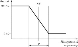
where P is the proportional band;
ST - regulation set point.
For example:
measurement range 0…1000 °С;
control set point ST = 500 °С;
proportional band P = 5%, which is 50 °C (5% of 1000 °C);
at a temperature value of 475 °C and below, the control signal will have a value of 100%; at 525 °C and above - 0%. In the range of 475…525 °C (in the proportional band), the control signal will change in proportion to the mismatch value with a gain K = 100/P = 20.
Reducing the value of the proportional band P increases the controller's response to mismatch, i.e., a small mismatch will correspond to a larger value of the control signal. But at the same time, due to the large gain, the process takes on an oscillatory character around the setpoint value, and precise control cannot be achieved. With an excessive increase in the proportional band, the controller will react too slowly to the resulting mismatch and will not be able to keep track of the process dynamics. In order to compensate for these disadvantages of proportional control, an additional time characteristic is introduced - the integral component.
integral component
It is determined by the integration time constant I, is a function of time and provides a change in the gain (shift of the proportional band) over a given period of time.
control signal = 100/P E + 1/I ∫ E dt.
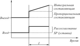
As can be seen from the figure, if the proportional component of the control law does not provide a decrease in the mismatch, then the integral component begins to gradually increase the gain over the time period I. After a period of time I, this process is repeated. If the mismatch is small (or rapidly decreases), then the gain does not increase and, if the value of the parameter is equal to the specified setting, takes some minimum value. In this regard, the integral component is referred to as the automatic control shutdown function. In the case of PID control, the step response of the process will be fluctuations that gradually decay towards the setpoint.
Derivative term
Many control objects are quite inertial, i.e. they have a delay in response to the applied action (dead time) and continue to respond after the control action is removed (delay time). PID controllers on such objects will always be late with turning on/off the control signal. To eliminate this effect, a differential component is introduced, which is determined by the differentiation time constant D, and full implementation of the PID control law is provided. The differential component is the time derivative of the mismatch, i.e. it is a function of the rate of change of the control parameter. In the event that the mismatch becomes constant value, the differential component ceases to affect the control signal.
control signal = 100/P E + 1/I ∫ E dt + D d/dt E.
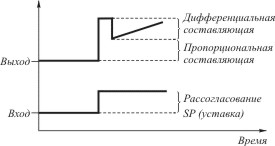
With the introduction of the differential component, the controller begins to take into account dead time and delay time, changing the control signal in advance. This makes it possible to significantly reduce fluctuations of the process around the setpoint value and to achieve a faster completion of the transient.
Thus, when generating a control signal, PID controllers take into account the characteristics of the control object itself, i.e. analyze the mismatch for the magnitude, duration and rate of change. In other words, the PID controller "anticipates" the reaction of the regulated object to the control signal and begins to change the control action not when the setpoint value is reached, but in advance.
5. The transfer function of which link is represented: K (p) \u003d K / Tr
In systems with this method of regulation, due to the presence of hysteresis and the limited control signal, the actual value of the parameter will always periodically fluctuate relative to the set value, i.e., there will always be a mismatch. It is possible to slightly increase the control accuracy by reducing the switching hysteresis, but this leads to an increase in the switching frequency of the output relay and a decrease in it. life cycle. Thus, controllers of this type are unsuitable for tasks where the control parameter is highly dynamic and where precise maintenance of the value of the controlled parameter is required. Possible application of limit controllers - objects with high inertia and low requirements for control accuracy.
PID control
You can significantly improve the accuracy of regulation by applying the PID law (Proportional-Integral-Differential regulation law).
To implement the PID law, three main variables are used:
P – proportional band, %;
I – integration time, s;
D is the differentiation time, s.
Manual tuning of the PID controller (determining the values of the parameters P, I, D), which provides the required quality of regulation, is rather complicated and is rarely used in practice. The UT/UP series PID controllers provide automatic tuning of PID parameters for a specific control process, while maintaining the possibility of manual adjustment.
Proportional
In the proportional band, determined by the coefficient P, the control signal will change in proportion to the difference between the setpoint and the actual value of the parameter (mismatch):
control signal = 100/P E,
where E is the mismatch.
The coefficient of proportionality (gain) K is inversely proportional to P:
The proportional band is determined with respect to the set control setpoint, and within this band the control signal changes from 0 to 100%, i.e. if the actual value and the setpoint are equal, the output signal will have a value of 50%.
where P is the proportional band;
ST - regulation set point.
For example:
measurement range 0…1000 °С;
control set point ST = 500 °С;
proportional band P = 5%, which is 50 °C (5% of 1000 °C);
at a temperature value of 475 °C and below, the control signal will have a value of 100%; at 525 °C and above - 0%. In the range of 475…525 °C (in the proportional band), the control signal will change in proportion to the mismatch value with a gain K = 100/P = 20.
Reducing the value of the proportional band P increases the controller's response to mismatch, i.e., a small mismatch will correspond to a larger value of the control signal. But at the same time, due to the large gain, the process takes on an oscillatory character around the setpoint value, and precise control cannot be achieved. With an excessive increase in the proportional band, the controller will react too slowly to the resulting mismatch and will not be able to keep track of the process dynamics. In order to compensate for these disadvantages of proportional control, an additional time characteristic is introduced - the integral component.
integral component
It is determined by the integration time constant I, is a function of time and provides a change in the gain (shift of the proportional band) over a given period of time.
control signal = 100/P E + 1/I ∫ E dt.
As can be seen from the figure, if the proportional component of the control law does not provide a decrease in the mismatch, then the integral component begins to gradually increase the gain over the time period I. After a period of time I, this process is repeated. If the mismatch is small (or rapidly decreases), then the gain does not increase and, if the value of the parameter is equal to the specified setting, takes some minimum value. In this regard, the integral component is referred to as the automatic control shutdown function. In the case of PID control, the step response of the process will be fluctuations that gradually decay towards the setpoint.
Derivative term
Many control objects are quite inertial, i.e. they have a delay in response to the applied action (dead time) and continue to respond after the control action is removed (delay time). PID controllers on such objects will always be late with turning on/off the control signal. To eliminate this effect, a differential component is introduced, which is determined by the differentiation time constant D, and full implementation of the PID control law is provided. The differential component is the time derivative of the mismatch, i.e. it is a function of the rate of change of the control parameter. In the case when the mismatch becomes a constant value, the differential component ceases to affect the control signal.
control signal = 100/P E + 1/I ∫ E dt + D d/dt E.
With the introduction of the differential component, the controller begins to take into account dead time and delay time, changing the control signal in advance. This makes it possible to significantly reduce fluctuations of the process around the setpoint value and to achieve a faster completion of the transient.
Thus, when generating a control signal, PID controllers take into account the characteristics of the control object itself, i.e. analyze the mismatch for the magnitude, duration and rate of change. In other words, the PID controller "anticipates" the reaction of the regulated object to the control signal and begins to change the control action not when the setpoint value is reached, but in advance.
When creating various automation devices, the task is often to provide a given speed of rotation of the motor shaft, independent of the current load.
It is not difficult to see that the speed of rotation of the motor shaft depends not only on the voltage on the motor, but also on external unknown influences on the motor, such as variable friction force, changing load, temperature, lubrication quality, and other factors. Therefore, the task of providing a given speed of rotation of the motor shaft is reduced to the task of generating such a voltage on the engine that would provide a given speed of rotation of the engine, independent of the influence of external random factors.
Solving this problem without theory automatic control impossible. The solution of the problem consists in the calculation and implementation PID speed controller. Dean-Soft specialists have experience in solving such problems.
The PID controller provides a given speed on the actuator (motor), independent of the constant or slowly changing load acting on it.
The PID controller is a proportional-integral-differential controller. The PID controller consists respectively of the proportional ( K p ), integral ( K and / s ) and differential ( K d s ) link, each of them has its own gain (Fig. 1).
Rice. 1. Structural diagram of a control system with a PID controller.
Here: s is the Laplace operator (sometimes referred to as p ). If we abstract from the Laplace transforms, then the records K p, K and / s and K d s should be taken only as a designation of the corresponding link, and not as a mathematical expression. And you definitely shouldn't look for meaning s , because, as already said, it's an operator, not a variable.
In a PID system, the actual speed V(t) motor is measured using sensor.
At system input speed setpoint arrives V ass(t) in the same units as the actual speed.
Feedback adder subtracts from the speed reference signal V ass (t) actual speed signal V(t) and generates an error signal e (t) at the output:
The error signal is sent to proportional, integral and differential links of the PID controller.
proportional link multiplies the error signal e by a factor K p and generates an output signal y p.
integral link integrates the signal e (t) over time, multiplies by a factor K and and generates an output signal y and.
differential link differentiates the error signal with respect to time e (t), multiplying the result by the number K d and output signal shaping y d.

PID controller accumulator sums the signals y p(t), y and(t) and y d(t) and generates an output signal y(t):
PWM and power switch designed to transmit the calculated output signal to the engine y(t).
Calculation of the coefficients of the PID controller
It is not difficult to see that the PID controller is characterized by three coefficients K p, K and and K d. To calculate these coefficients, it is necessary to know the parameters of the control object, in this case the engine.
Structure and parameters of the control object
From the point of view of the theory of automatic control, the engine direct current approximately described by: two aperiodic links with electrical time constant T e and mechanical time constant T m. Overall motor gain K motor(Fig. 2). In fact, structural scheme the engine is much more complicated, but this is not so important for us in this case.

Rice. 2. Structural diagram of the engine from the point of view of the theory of automatic control.
Motor transfer function, written in terms of the Laplace operator s, the following:

Engine GainK motor determines the proportionality between the speed of rotation of the engine shaft at idle and the voltage applied to the input. Simply put, the ratio is equal to the ratio of idle speed V xx and motor rated voltage U n.
The voltage on the motor in microprocessor technology is set in arbitrary units of voltage, and the speed is taken in conventional units of speed.
If a 7-bit PWM is used to generate the voltage on the motor (see below), then to calculate K motor the value of the rated voltage is 128 conventional voltage units.
idle speed w xx, specified in the passport data of the engine, should be re-read in conventional units of speed Vxx determined by the way the speed sensor is implemented.
For example, suppose an incremental encoder is used to measure speed, located on the motor shaft and having 512 marks per revolution. Let the speed in conventional units be measured as the number of marks per cycle of calculation D t. Let the calculation cycle, obtained by evaluating the performance of the algorithm, be equal to 0.001 sec. Let the engine idle speed w xx=5000 rpm.
Let's translate the engine speed into sensor marks, we get: 5000x512 = 2560000 marks / min. Let's convert minutes into cycles of calculation:
If the engine parameters are unknown, then the idle speed is determined experimentally. To do this, at idle, maximum voltage is applied to the engine and readings are taken from the speed sensor V xx.
Mechanical time constant T m depends on the moment of inertia of the motor shaft, gearbox, inertia executive device. It is usually not possible to calculate its value analytically. Therefore, it is measured experimentally.
To do this, the maximum voltage is abruptly applied to the engine at its rated load and the transient process of speed change is removed V(t).
The speed is taken from the speed sensor at discrete times, recorded in the RAM of the microprocessor, and then transferred to a personal computer. Personal computer reconstructs the speed change graph V(t)(Fig. 3).
 |
Rice. 3. Transient process in a DC motor.
According to the transient graph, it is possible to determine, firstly, the idle speed V xx, and secondly, the regulation time t p. The control time is determined by the end time of the transient process (the time when the transient curve differs by less than 1% from the steady state value).
If we neglect the small influence of the electrical time constant T e, usually an order of magnitude smaller than the mechanical time constant T m, then the transient process in a DC motor can be considered aperiodic with a constant T m.
It is known that the time of an aperiodic transient process is five times longer than its time constant. Those.:
Hence for our case we get:
In our case, the control time t p, judging by the graph, is equal to 1.5 sec. Then the mechanical time constant T m= 1.5/5 = 0.3 sec.
Thus, having plotted the transient process graph, we find the mechanical time constant T m.
Electrical time constantT e determines the inertia of the motor armature magnetization and is equal to the ratio of the motor armature inductance to the resistance of its winding:
In practice, armature inductance parameters are difficult to measure, and then they take the electrical time constant an order of magnitude less than the mechanical time constant:
This is true for most engines.
Calculation of the coefficients of the PID controller.
To calculate the coefficients of the PID controller, one should solve the inverse problem of dynamics. To do this, we abstract from the PID controller. We will assume that the controller structure, i.e. its transfer function W p(s) , is unknown to us. For this, the transfer function of the control object is known Wdv(s)(Fig. 4).

Rice. 4. Initial scheme for calculating the controller for a DC motor.
We write the transfer function of the closed system W s (s):
Let's determine what transient process in the system would suit us? We are quite satisfied with the aperiodic transient process in the system. This is how the system should respond to changes in speed and load.
Let the desired time constant of the transient T will be approximately equal T m. Those. transfer function of the desired system w(s) is equal to:

Let us equate the transfer function of the closed system to the transfer function of the desired system:
By simple mathematical transformations, we express from here the expression for the transfer function of the controller W p(s):
Substitute the value W motor(s):
Let's introduce coefficients:
We get:

It is not difficult to see that we just got the coefficient C 1 , coefficient before the integral link FROM 2 and the coefficient in front of the differentiating link C 3 . Those. we got the classic PID controller structure with parameters K p=FROM 1 , K and=C 2 and K d=C 3 :
Implementation of a PID controller on a digital microprocessor
Systems with PID controllers are currently implemented only digitally, and the calculation of control laws is performed by cheap microprocessors of the AVR or MCS -51 series. Note that microprocessors are integer and do not support floating point operations. This requires the programmer to adapt the algorithms accordingly.
In a PID system, the speed of the motor is measured using a sensor. Real speed is measured in integer conditional units of speed. Usually, conventional units of speed are selected in such a way that the speed in c.u. changed in the range from -127 to 127 (one byte), in extreme cases from -15 to 15 (the speed is taken with a margin). But in any case, the number of speed increments should not be less than the required number of speeds.
Speed can be measured by the following sensors:

The specified speed is input to the system in the same conventional units as the real speed. The set speed is usually transmitted from a higher-level control processor or a personal computer, and stored in the appropriate memory cells of the microprocessor.
Feedback adder subtracts from set speed V ass real speed V and receives the so-called error signal e:
Considering that the speed V ass and V are integers in the range -127 to 127, this operation is implemented quite simply on an integer microprocessor. It should be ensured that the result. If e<-127 , то e =127, а если e >12 7, then e = 127.
Error signal e enters the input of the PID controller, i.e. on a proportional link, integral and differential.
proportional link generates an output signal y p by multiplying the instantaneous error signal by a factor K p.
Coefficient K p usually represents a non-integer value between 0.5 and 2. Therefore, to multiply an integer one-byte number e for this coefficient use the table K P,i, which is calculated in advance:
for i =-127...127Moreover, the numbers in the table take into account the restriction on the result, which should also turn out to be one-byte, not exceeding the value 127. That is, if the multiplication result is more than 127, then take it equal to 127, and if it is less than -127, then take it equal to -127 .
Programmers should understand that the processor considers a signed number i as an unsigned table index, so table elements with indexes from -128 to -1 will actually be in the index range from 128 to 255.
Then, multiplication by the coefficient K p replaced by table element selection K P,i with index e :
The table is usually calculated on a personal computer and flashed into the microprocessor memory.
integral link generates an output signal y and by integrating the error signal e by time and multiplication by a coefficient K and.
Here: T- time from start of work.
The digital microprocessor calculates the integral by stepwise integration with a step equal to the clock cycle of the timer D t. Thus, for the discrete case, the formula is replaced by:
Here k is the number of cycles of calculation that have passed since the start of work.
Consider the sum of all ek. Basically, it's just the sum of all the values e , received at each cycle. This sum is called the integral sum. S (not to be confused with s - the Laplace operator). The integral sum is implemented as a global variable and is increased at each cycle by the current value of the error signal e :

When calculating the PID controller, the coefficient K and usually between 0.05 and 2. Calculation cycle D t ranges from 0.0001 to 0.002 sec. Thus, the coefficient K and D t is from 5·10 -6 to 4·10 - 3 . Because this coefficient is much less than 1, then the problem of integer multiplication by it arises, since after multiplication will always be zero.
To solve this problem, let's try to multiply the coefficient K and D t for some big number A , and divide the integral sum by the same number:

Denote the product K and D t · A through the coefficient B :
Let's choose a number A , a multiple of 256 x to the coefficient B was in the range from 0.05 to 5.
In order to calculate the ratio S/A , expand the sign of the number S :
implement 16-bit calculation S, if A =256;
implement 24-bit calculation S, if A =256 2 ;
implement 32-bit calculation S, if A =256 3 .
It's not hard to implement adding to a 16, 24, or 32-bit signed number S signed 8-bit number e. Don't forget that if e If it is positive, then sign-extension will fill the high-order bits with zeros, and if negative, then the high-order bits will be filled with ones. To limit the accumulation of the integral sum, we implement an upper and lower limit. This is usually done as follows: if the most significant (sign) bit is not equal to the penultimate bit, then the growth of the integral sum should be suspended.
Recall that the division of any number by the number 256 x is equivalent to a right shift by x bytes to the right. Let's use this rule. Take only the high byte of the integral sum S : in the case of a 16-bit count, this is equivalent to a shift by one byte, in the case of a 24-bit count - by two bytes, in the case of a 32-bit count - by three bytes.
In this way:
Where: S older- high byte of the number S .
Multiplication by a factor B implement in the form of a table B i, similar to the calculation of the coefficient of the proportional link:

differential link
Derivative circuit calculates the output signal y d - e 0 we implement in the form of a table C i, as in the calculation of the proportional link:
PID controller accumulator
The adder after the PID controller adds the instantaneous values of the signals y p, y and and y d and generates an output signal y:
When summing, you should ensure that the result is in the range from -127 to +127, by implementing, for example, a 16-bit summation. If the result is greater than 127, it should be taken equal to 127, and if less than -127, then equal to -127.
The PWM signal is generated automatically by the AVR microprocessors. One microprocessor is capable of generating up to 3 hardware PWM signals. In addition, the PWM signal can be generated programmatically by timer.
It is convenient to form a 7-bit PWM. In this case, the control power switch can be connected according to the diagram shown in Fig. four.
Rice. 4. The way to connect the power switch to the PWM output.
High (sign) bit of the result y is output through any I / O pin to one of the inputs of the power switch, and the remaining 7 bits (the last bit is set to zero) without any conversion can be loaded into the PWM cutoff formation register.
Let's prove it.
Q.E.D.
We advise you to read
, diagnosis, treatment Treatment of urogenital chlamydia") Chlamydia urogenital - description, causes, symptoms (signs), diagnosis, treatment Treatment of urogenital chlamydia
Chlamydia urogenital - description, causes, symptoms (signs), diagnosis, treatment Treatment of urogenital chlamydia The benefits and significance of hydroamino acid threonine for the human body L threonine what
 To wait or not to wait for a guy from the army For what reason can they be commissioned from the army
 Baked apples with cottage cheese Baked apples with cottage cheese

