The basic principle underlying the operation of the UPS is to transform the network AC voltage(50 Hertz) into an alternating high-frequency voltage of a rectangular shape, which is transformed to the required values, rectified and filtered.
The conversion is carried out with the help of powerful transistors operating in the mode of a key and a pulse transformer, together forming an RF converter circuit. As for the circuit design, there are two possible options for converters: the first one is performed according to the pulse self-oscillator circuit and the second one is with external control (used in most modern radio-electronic devices).
Since the frequency of the converter is usually chosen on average from 20 to 50 kilohertz, the dimensions of the pulse transformer, and, consequently, of the entire power supply, are sufficiently minimized, which is a very important factor for modern equipment.
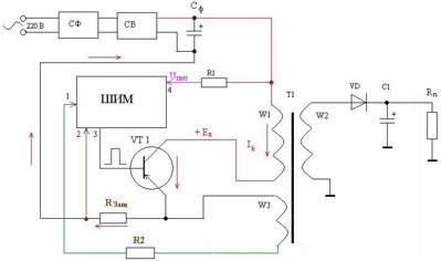
A simplified diagram of an externally controlled pulse converter, see below:
The converter is made on a transistor VT1 and a transformer T1. The mains voltage through the network filter (SF) is supplied to the mains rectifier (CB), where it is rectified, filtered by the filter capacitor Cf and through the winding W1 of the transformer T1 is fed to the collector of the transistor VT1. When a rectangular pulse is applied to the base circuit of the transistor, the transistor opens and an increasing current Ik flows through it. The same current will also flow through the winding W1 of the transformer T1, which will lead to the fact that the magnetic flux increases in the core of the transformer, while the EMF of self-induction is induced in the secondary winding W2 of the transformer. Eventually, a positive voltage will appear at the output of the VD diode. Moreover, if we increase the duration of the pulse applied to the base of the transistor VT1, the voltage will increase in the secondary circuit, because more energy will be given off, and if we reduce the duration, the voltage will decrease accordingly. Thus, by changing the pulse duration in the base circuit of the transistor, we can change the output voltages secondary winding T1, and therefore to stabilize the output voltages of the PSU. The only thing that is needed for this is a circuit that will generate trigger pulses and control their duration (width). A PWM controller is used as such a circuit. PWM stands for Pulse Width Modulation. The PWM controller includes a master pulse generator (which determines the frequency of the converter), protection and control circuits, and a logic circuit that controls the pulse duration.
To stabilize the output voltages of the UPS, the PWM controller circuit "must know" the value of the output voltages. For these purposes, a tracking circuit (or feedback circuit) is used, made on the optocoupler U1 and the resistor R2. An increase in voltage in the secondary circuit of the transformer T1 will lead to an increase in the intensity of the LED radiation, and consequently a decrease in the resistance of the transition of the phototransistor (which are part of the optocoupler U1). Which in turn will lead to an increase in the voltage drop across the resistor R2, which is connected in series with the phototransistor and a decrease in the voltage at pin 1 of the PWM controller. Reducing the voltage causes the logic circuit, which is part of the PWM controller, to increase the pulse duration until the voltage at the 1st output matches the specified parameters. When the voltage decreases, the process is reversed.
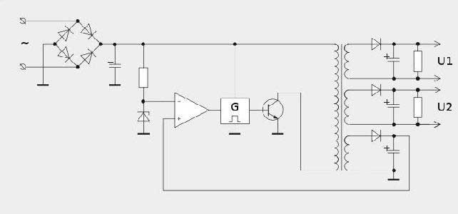
The UPS uses 2 principles for implementing tracking circuits - “direct” and “indirect”. The method described above is called "direct", since the feedback voltage is taken directly from the secondary rectifier. With "indirect" tracking, the feedback voltage is removed from the additional winding of the pulse transformer:
A decrease or increase in the voltage on the winding W2 will also lead to a change in the voltage on the winding W3, which is also applied to pin 1 of the PWM controller through resistor R2.
I think we figured out the tracking circuit, now let's consider such a situation as a short circuit (short circuit) in the UPS load. In this case, all the energy given to the secondary circuit of the UPS will be lost and the output voltage will be almost zero. Accordingly, the PWM controller circuit will try to increase the pulse duration in order to raise the level of this voltage to the appropriate value. As a result, the transistor VT1 will be longer and longer in the open state, and the current flowing through it will increase. In the end, this will lead to the failure of this transistor. The UPS is designed to protect the inverter transistor from overcurrent in such abnormal situations. It is based on the resistor Rprotect, connected in series to the circuit through which the collector current Ik flows. An increase in the current Ik flowing through the transistor VT1 will increase the voltage drop across this resistor, and, therefore, the voltage supplied to pin 2 of the PWM controller will also decrease. When this voltage drops to a certain level that corresponds to the maximum admissible current transistor, the logic circuit of the PWM controller will stop generating pulses at pin 3 and the power supply will go into protection mode or, in other words, turn off.
In conclusion, the topic would like to describe in more detail the advantages of the UPS. As already mentioned, the frequency of the pulse converter is quite high, and therefore, the overall dimensions of the pulse transformer are reduced, which means, paradoxically as it sounds, the cost of a UPS is less than a traditional PSU, since there is less metal consumption for the magnetic circuit and copper for the windings, not even despite the fact that the number of parts in the UPS increases. Another advantage of the UPS is the small capacitance of the filter capacitor of the secondary rectifier compared to a conventional power supply. The reduction in capacitance was made possible by increasing the frequency. And, finally, the efficiency of the switching power supply reaches 85%. This is due to the fact that the UPS consumes energy electrical network only during the open transistor of the converter, when it is closed, energy is transferred to the load due to the discharge of the filter capacitor of the secondary circuit.
The disadvantages include the complication of the UPS circuit and the increase in impulse noise emitted by the UPS itself. The increase in noise is due to the fact that the converter transistor operates in the key mode. In this mode, the transistor is a source of impulse noise that occurs at the moments of transient processes of the transistor. This is a disadvantage of any transistor operating in the key mode. But if the transistor operates with low voltages (for example, transistor logic with a voltage of 5 volts), this is not a problem, in our case, the voltage applied to the collector of the transistor is approximately 315 volts. To combat this interference, the UPS uses more sophisticated network filter circuits than a conventional PSU.
Between transformer and pulse, as well as their advantages and disadvantages. For example, a transformer power supply, which includes a transformer that performs the function of lowering the mains voltage to a predetermined one, such a design is called a step-down transformer.
Power supplies operating in pulsed mode are pulse converter or an inverter. In switching power supplies, the alternating voltage at the input is first rectified, and then the pulses of the required frequency are formed. Such a power supply, unlike an ordinary power transformer, with the same power, has much less losses and small overall dimensions obtained as a result of high-frequency conversion. p>
Transformer power supplies
The most common power supply is considered to be a design that includes a step-down transformer, its specific duty is to lower the input voltage. Its primary winding is wound to work with mains voltage. In addition to the step-down transformer, a rectifier assembled on diodes is also installed in such a power supply unit; as a rule, two pairs of rectifier diodes are used ( diode bridge) and filter capacitors. Such a device is used to convert a unidirectional pulsating alternating voltage into a constant one. Not infrequently, other structurally designed devices are also used, for example, performing the function of doubling the voltage in rectifiers. In addition to smoothing ripple filters, there may also be elements of a noise filter high frequency and surges, protection circuit against short circuit, semiconductor devices for voltage and current stabilization.

Scheme of the simplest transformer power supply unit with a full-wave rectifier
Advantages of transformer power supplies
Switching power supplies
Differences between a switching power supply and a conventional one- switching power supplies are an inverter device and are an integral part of uninterruptible power supply devices. In pulse blocks, the alternating voltage at the input is first rectified, and then it forms pulses of a certain frequency. The converted output DC voltage has high frequency rectangular pulses fed to the transformer or directly to the output low-pass filter. Small-sized transformers are often used in switching power supplies - this is due to the fact that with increasing frequency, the efficiency of the device increases, thereby reducing the requirements for the dimensions of the magnetic circuit necessary to deliver equivalent power. Basically, such a magnetic circuit is made of ferromagnetic materials serving as conductors of the magnetic flux. Power source differences in particular, from the core of a low-frequency transformer, for the manufacture of which electrical steel is used.
Differences between a switching power supply and a conventional one- the voltage stabilization that occurs in switching power supplies occurs due to the negative feedback circuit. OOS makes it possible to provide the output voltage at a fairly stable level, regardless of the periodic jumps in the input voltage and the value of the load resistance. Negative feedback can also be created in other ways. Relatively impulse sources power supply with galvanic isolation from the electrical network, the most commonly used method in such cases is the formation of a connection using the output winding of the transformer or use an optocoupler. Taking into account the value of the negative feedback signal, which depends on the output voltage, the duty cycle of the pulse signals at the output pin of the PWM controller changes. If it is possible to do without galvanic isolation, then, in this case, a conventional voltage divider assembled on fixed resistors is used. Ultimately, the power supply provides a stable output voltage.
Schematic diagram of the simplest single-cycle pulsed power supply
Advantages of switching power supplies
● If we compare a linear stabilizer and a pulse stabilizer with respect to output power, then the latter has some advantages:
● Relatively light weight, resulting from the fact that with increasing frequency it is possible to use transformers of small dimensions with a similar output power.
● The large weight of the linear stabilizer is obtained through the use of massive power transformers, as well as heavy heat sinks of power components.
● High efficiency, which is about 98%, obtained due to the fact that the regular losses occurring in pulse stabilizing devices depend on transients at the key switching stage.
● Since the keys are in a stable or on or off state for a longer period of time, then, accordingly, the energy losses are negligible;
● Relatively low cost resulting from the release of a large number of necessary electronic components, in particular the appearance of high-power transistor switches on the electronic goods market. ● In addition to all this, it is necessary to note the significantly low cost of pulse transformers with a similar power delivered to the load.
● Available in the vast majority of power supplies established schemes protection against all sorts of abnormal situations, such as protection against short circuits or if the load is not connected at the output of the device.
Technological progress does not stand still, and today pulse blocks have replaced transformer-type power supplies. There are many reasons for this, but the most important are:
- Simplicity and cheapness in production;
- Ease of use;
- Compactness and significantly comfortable overall dimensions.
Read the guide on how to choose a detector concealed wiring and how to use it.
From a technical point of view, a switching power supply is a device that rectifies the mains voltage and then forms a pulse from it with a frequency response of 10 kHz. It is worth noting that the efficiency of this technical device reaches 80%.
Principle of operation
In fact, the whole principle of operation of a switching power supply comes down to the fact that a device of this type is aimed at rectifying the voltage that is supplied to it when connected to the network and then form a working impulse, due to which this electrical unit can function.
Many people ask, what are the main differences between a pulsed device and a conventional one? It all comes down to the fact that it has elevated specifications and smaller dimensions. Also, the impulse block gives more energy than its standard version.
Kinds
Currently in the territory Russian Federation if necessary, you can find power supplies impulse type the following varieties and categories:
Scheme
All pulse-type power supplies, depending on the scope of operation and technical features have different schemes:
The initial distribution of switching power supplies (IPB) was received mainly in TVs, later - in VCRs, video equipment and other household appliances, which is mainly due to two reasons. Firstly, the sensitivity of TVs and VCRs to the generated impulse power supply interference is much lower than, for example, sound reproduction equipment, especially high-quality ones. Secondly, television receivers and video recorders are characterized by relative constancy and a relatively small amount (10 ... 80 W) of power consumed in the load.
Fluctuations in this power in kinescope TVs are due to changes in screen brightness when changing scenes and is no more than 20 W (approximately 30% of the maximum power consumption). For VCRs, fluctuations in the power consumed in the load occur mainly only when switching the modes of operation of the tape drive mechanism (LPM) and do not exceed a few watts. For example, in a stereo amplifier with an output power of 2 x 20 watts, the power fluctuation reaches 70-80 watts (approximately 70-80% of the maximum power consumption). Therefore, for this class of radio equipment, UPSs turn out to be more expensive due to the need to use powerful push-pull circuits of converters (converters), more complex stabilizers, filters, etc.
In this regard, the designers of both earlier and modern models of televisions, video equipment and other household appliances, as a rule, adhere to well-established principles of reliability, efficiency and simplicity in terms of building switching power supplies. The main efforts are directed, first of all, to the improvement and microminiaturization element base, increasing the reliability of the UPS (including by introducing various protections) and expanding the operating range of the mains voltage supplying them.
Structural diagram of a switching power supply
In practice, in the designs of switching power supplies for TVs and VCRs, UPSs based on an adjustable converter with a transformerless input are most widely used.
The block diagram of a switching power supply consists of two main elements: a mains rectifier CB and a voltage converter PN.
The mains rectifier performs the functions of rectifying the mains voltage Uc and smoothing ripples, provides a smooth charge mode for the filter capacitors when the power supply is turned on, uninterrupted power supply to the load during short-term voltage dips below the permissible level and reduces the level of interference through the use of special noise suppression filters (in more detail, methods of combating with interference in switching power supplies will be discussed later).
The voltage converter includes a Kv converter and a controller (control device) K. The converter, in turn, consists of an adjustable inverter And, a pulse transformer T, rectifiers B and stabilizers CM of the secondary supply voltage Un. The inverter converts the DC output voltage of the CB into a variable square wave. The pulse transformer operates at an increased frequency (more than 20 kHz) and provides the autogenerator mode of the inverter, obtaining the voltages necessary to power the controller itself, protection circuits and load circuits of the PSU, as well as galvanic isolation of the network from the load.
The controller performs pulse control of a powerful transistor switch of the inverter (for the reasons indicated above, only converters based on a single-cycle self-excited inverter (oscillators) are mainly used in TVs and video equipment). In addition, the controller is entrusted with the functions of stabilizing the voltage at the load, as well as protecting the PSU from overvoltage (boost), output current overloads, voltage drops (buck) and overheating. In some designs, the function of remote on / off device is additionally implemented directly in the controller circuit.

Rice. 1. Generalized block diagram of a switching power supply
The UPS controller includes the following functional units: power supply for the IPK controller; pulse duration modulator MDI; ultrasonic protection device; logic circuit of the LAN for combining the MDI and US signals; FUN control voltage driver for a powerful converter transistor.
In controllers for television and video equipment, as a rule, IPC circuits are used based on triggering chains that are briefly connected to the output voltage of the mains rectifier, followed by switching to power from a special winding of the pulse transformer T.
The pulse duration modulator (MDI) generates a pulse sequence with a given ratio of pulse duration to pause duration (duty cycle). Depending on the method of controlling a powerful transistor of a converter in MDI, the following types of modulation can be used: phase-pulse (PIM); frequency-pulse (PFM); pulse-width (PWM). In pulse power supplies, PWM-based MDIs are most widely used due to the simplicity of circuit implementation, and also because in PWM voltage converters, the switching frequency remains unchanged, and only the pulse duration changes. In PIM and PFM converters, the switching frequency changes during the regulation process, which is their main disadvantage, which limits the use of TV and VM in UPS (noise).
Rice. 2. Structural diagram of the pulse duration modulator
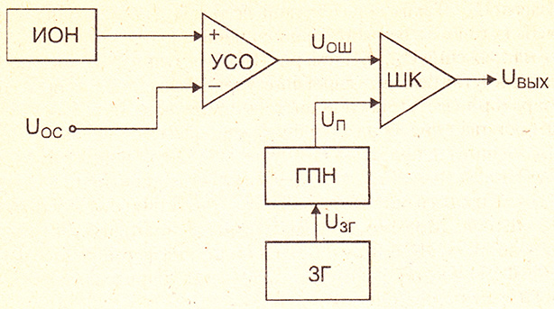
We will consider the principles of construction and operation of MDI based on pulse-width modulation (PWM modulator) in more detail. The MDI includes the following functional units (Fig. 2): reference voltage source ION; error signal amplifier (mismatch) USO; master oscillator ZG; sawtooth voltage generator GPN; PWM comparator ShK.
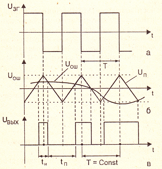
Rice. 3. Plots characterizing the operation of the PWM modulator
The PWM modulator works as follows. The CG generates rectangular oscillations (Fig. 3, a) with a frequency equal to the operating frequency of the voltage converter. Formed from these oscillations in the GPN sawtooth voltage Up (Fig. 3, b) enters the input of the PWM comparator ShK, the other input of which receives a signal from the output of the error signal amplifier. The output signal of the USO Uos is proportional to the difference between the reference voltage and the voltage generated by the feedback circuit Uoc. Thus, the voltage Ush is a mismatch signal, the level of which changes in proportion to the change in the load current In or the output voltage Uout of the PSU (see Fig. 1). As a result of such a circuit design, a closed circuit for regulating the output voltage level is formed.
The PWM comparator is a linear-discrete functional unit of the MDI. The input to which the sawtooth voltage is supplied is the reference input, and the second input is the control input. The output signal is ShK-pulse. The duration of the output pulses (Fig. 3., c) is determined by the level of excess of the control signal Uosh over the reference Up and changes during operation in accordance with the change in the input control signal. The duration-modulated output pulses of the SC through the logic circuit of the LS (see Fig. 1) are fed to the control voltage shaper FUN, in which the control signal is generated by switching the powerful switching transistor of the converter.
The stabilization of the output voltage Un is realized due to the fact that when the output voltage of the converter changes, the feedback voltage Uoc also changes, causing a change in the duration of the pulses at the output of the barcode, and this, in turn, causes a change in the power supplied to the secondary circuits. This ensures the stability of the output voltage of the PV in terms of the average value.
One of the main requirements for switching power supplies is to provide galvanic isolation of the supply network and the load connected via feedback circuits to the ultrasonic protection device and the USO error signal amplifier.
Optoelectronic pairs (optocouplers) or transformers are currently used as decoupling elements. The undoubted advantages of optocoupler isolation in comparison with transformer isolation are its manufacturability, small dimensions and the ability to transmit signals in a wide frequency range.
However, transformer isolation makes it possible to get by with a smaller number of intermediate amplifiers in the UPS controller, to make it easier to match with high-voltage sources of feedback signals (for example, in TV power supplies that use flyback pulses for PWM control). line scanning). However, at present, when developing switching power supplies, designers increasingly prefer optocoupler decoupling circuits.
In conclusion, we note that the main trend in the improvement of switching power supplies for household video equipment is the transition from designs based on discrete elements to designs of power supplies that are almost completely made on integrated circuits. First of all, this concerns the circuits of UPS controllers and stabilizers of secondary load voltages. Separately, it is necessary to say about powerful high-voltage transistor switches. Currently, IC controllers with a built-in power switch are increasingly being used, and bipolar transistors are being replaced by powerful CMOS transistors. The main advantages of CMOS switches are their simpler control, increased resistance to secondary breakdown due to a decrease in the probability of local non-heating of the crystal, increased (up to 0.1-1.0 MHz) switching frequency (there is no charge accumulation in them).
An integral part of every computer is power supply (PSU). It is as important as the rest of the computer. At the same time, the purchase of a power supply is quite rare, since a good PSU can provide power for several generations of systems. Given all this, the purchase of a power supply must be taken very seriously, since the fate of a computer is directly dependent on the operation of the power supply.
The main purpose of the power supply issupply voltage generation, which is necessary for the functioning of all PC units. The main supply voltages of the components are:
- +3.3V
There are also additional voltages:
For implementation galvanic isolation it is enough to make a transformer with the necessary windings. But to power a computer, you need a lot of energy. power, especially for modern PCs. For computer power supply one would have to manufacture a transformer that would not only have a large size, but also weigh a lot. However, with an increase in the frequency of the supply current of the transformer, to create the same magnetic flux, fewer turns and a smaller cross section of the magnetic circuit are needed. In power supplies built on the basis of a converter, the frequency of the transformer supply voltage is 1000 or more times higher. This allows you to create compact and lightweight power supplies.
The simplest switching power supply
Consider a block diagram of a simple switching power supply, which underlies all switching power supplies.
.
The first block does conversion of alternating mains voltage to direct. Such converter consists of a diode bridge that rectifies the alternating voltage, and a capacitor that smooths out the ripple of the rectified voltage. In this bokeh are also additional elements: mains voltage filters against pulse generator ripples and thermistors to smooth the current surge at the moment of switching on. However, these elements may be omitted in order to save on cost.
The next block is pulse generator, which generates pulses at a certain frequency that feed the primary winding of the transformer. The frequency of the generating pulses of different power supplies is different and lies in the range of 30 - 200 kHz. The transformer performs the main functions of the power supply: galvanic isolation from the network and lowering the voltage to the required values.
The alternating voltage received from the transformer is converted by the next block into direct voltage. The block consists of voltage rectifying diodes and a ripple filter. In this block, the ripple filter is much more complex than in the first block and consists of a group of capacitors and a choke. In order to save money, manufacturers can install small capacitors, as well as chokes with low inductance.
First impulse power block represented push-pull or single-stroke converter. Push-pull means that the generation process consists of two parts. In such a converter, two transistors open and close in turn. Accordingly, in a single-cycle converter, one transistor opens and closes. Schemes of push-pull and single-cycle converters are presented below.
.
Consider the elements of the scheme in more detail:
X2 - circuit power supply connector.
X1 - connector from which the output voltage is removed.
R1 - resistance that sets the initial small offset on the keys. It is necessary for a more stable start of the oscillation process in the converter.
R2 is the resistance that limits the base current on the transistors, this is necessary to protect the transistors from burning.
TP1 - The transformer has three groups of windings. The first output winding generates the output voltage. The second winding serves as a load for the transistors. The third one forms the control voltage for the transistors.
At the initial moment of turning on the first circuit, the transistor is slightly ajar, since a positive voltage is applied to the base through the resistor R1. A current flows through the ajar transistor, which also flows through the second winding of the transformer. The current flowing through the winding creates a magnetic field. The magnetic field creates voltage in the remaining windings of the transformer. As a result, a positive voltage is created on winding III, which further opens the transistor. The process continues until the transistor enters saturation mode. The saturation mode is characterized by the fact that as the applied control current to the transistor increases, the output current remains unchanged.
Since the voltage in the windings is generated only in the event of a change magnetic field, its growth or fall, then the absence of an increase in current at the output of the transistor, therefore, will lead to the disappearance of the EMF in the windings II and III. Loss of voltage in the winding III will lead to a decrease in the degree of opening of the transistor. And the output current of the transistor will decrease, therefore, the magnetic field will also decrease. Reducing the magnetic field will create a voltage of opposite polarity. The negative voltage in winding III will begin to close the transistor even more. The process will continue until the magnetic field disappears completely. When the magnetic field disappears, the negative voltage in winding III will also disappear. The process will start repeating again.
A push-pull converter works on the same principle, but the difference is that there are two transistors, and they open and close in turn. That is, when one is open, the other is closed. The push-pull converter circuit has the great advantage of using the entire hysteresis loop. magnetic conductor transformer. Using only one section of the hysteresis loop or magnetization in only one direction leads to many undesirable effects that reduce the efficiency of the converter and degrade its performance. Therefore, basically, a push-pull converter circuit with a phase-shifting transformer is used everywhere. In circuits where simplicity, small size, and low power are needed, a single-cycle circuit is still used.
ATX form factor power supplies without power factor correction
The converters discussed above, although they are finished devices, are inconvenient to use in practice. Converter frequency, output voltage and many other parameters “float”, change depending on the change: supply voltage, converter output load and temperature. But if the keys are controlled by a controller that could perform stabilization and various additional functions, then you can use the circuit to power the devices. The power supply circuit using a PWM controller is quite simple, and, in general, is a pulse generator built on a PWM controller.
PWM - pulse width modulation. It allows you to adjust the amplitude of the signal of the passed low-pass filter (filter low frequencies) with a change in the duration or duty cycle of the pulse. The main advantages of PWM are the high efficiency of power amplifiers and great application possibilities.
This power supply circuit has a low power and uses a field effect transistor as a key, which makes it possible to simplify the circuit and get rid of the additional elements necessary to control the transistor switches. IN high power power supplies PWM controller has controls ("Driver") output key. IGBT transistors are used as output keys in high power power supplies.
The mains voltage in this circuit is converted into a constant voltage and fed through the key to the first winding of the transformer. The second winding serves to power the microcircuit and form a feedback voltage. The PWM controller generates pulses with a frequency that is set by the RC circuit connected to leg 4. The pulses are fed to the input of the key, which amplifies them. The duration of the pulses varies depending on the voltage on pin 2.
Consider a real ATX power supply circuit. It has a lot more elements and there are more additional devices in it. The red squares of the power supply circuit are conditionally divided into main parts.
ATX power supply circuit 150-300 W
To power the controller chip, as well as to generate a standby voltage of +5, which is used by the computer when it is turned off, there is another converter in the circuit. In the diagram, it is designated as block 2. As you can see, it is made according to the single-cycle converter circuit. The second block also has additional elements. Basically, these are surge absorption circuits that are generated by the converter transformer. Chip 7805 - the voltage regulator generates a standby voltage of + 5V from the rectified voltage of the converter.
Often, low-quality or defective components are installed in the standby voltage generation unit, which causes the frequency of the converter to decrease to the audio range. As a result, a squeak is heard from the power supply.
Since the power supply is powered by AC voltage 220V, and the converter needs power constant voltage, the voltage needs to be converted. The first block performs rectification and filtering of the alternating mains voltage. This block also contains a blocking filter against interference generated by the power supply itself.
The third block is the TL494 PWM controller. It performs all the basic functions of the power supply. Protects the power supply from short circuits, stabilizes the output voltage and generates a PWM signal to control transistor switches that are loaded on the transformer.
The fourth block consists of two transformers and two groups of transistor switches. The first transformer generates a control voltage for the output transistors. Since the TL494 PWM controller generates a low power signal, the first group of transistors amplifies this signal and passes it to the first transformer. The second group of transistors, or output ones, are loaded on the main transformer, which forms the main supply voltages. Such a more complex scheme for managing output keys is applied due to the complexity of managing bipolar transistors and protection of the PWM controller from high voltage.
The fifth block consists of Schottky diodes that rectify the output voltage of the transformer, and a low-pass filter (LPF). The low-pass filter consists of electrolytic capacitors of considerable capacity and chokes. At the output of the low-pass filter there are resistors that load it. These resistors are necessary so that after turning off the capacitance of the power supply, they do not remain charged. There are also resistors at the output of the mains voltage rectifier.
The remaining elements that are not circled in the block are chains, forming " health signals". These chains carry out the work of protecting the power supply from a short circuit or monitoring the health of the output voltages.
Now let's see how printed circuit board 200 W power supply elements are located. The figure shows:
Capacitors that filter the output voltages.
Place unsoldered output voltage filter capacitors.
Inductors that filter output voltages. The larger coil not only plays the role of a filter, but also acts as a ferromagnetic stabilizer. This allows you to slightly reduce voltage distortions with uneven loading of various output voltages.
Chip PWM stabilizer WT7520.
A radiator on which Schottky diodes are installed for voltages + 3.3V and + 5V, and ordinary diodes for voltage + 12V. It should be noted that often, especially in older power supplies, additional elements are placed on the same radiator. These are voltage stabilization elements + 5V and + 3.3V. In modern power supplies, only Schottky diodes for all basic voltages or field-effect transistors are placed on this radiator, which are used as a rectifier element.
The main transformer, which performs the formation of all voltages, as well as galvanic isolation from the network.
A transformer that generates control voltages for the output transistors of the converter.
Converter transformer that generates standby voltage + 5V.
The radiator, on which the output transistors of the converter are located, as well as the transistor of the converter that forms the standby voltage.
Mains voltage filter capacitors. They don't have to be two. To form a bipolar voltage and form a midpoint, two capacitors of equal capacity are installed. They divide the rectified mains voltage in half, thereby forming two voltages of different polarity connected in common point. In single supply circuits, there is only one capacitor.
Network filter elements from harmonics (interference) generated by the power supply.
Diode bridge diodes that rectify the AC voltage of the network.
Power supply 350 W set up equivalently. Immediately striking is the large board, enlarged heatsinks and a larger converter transformer.
Output voltage filter capacitors.
A heatsink that cools the diodes that rectify the output voltage.
PWM controller AT2005 (similar to WT7520), which performs voltage stabilization.
The main transformer of the converter.
A transformer that generates a control voltage for the output transistors.
Standby voltage converter transformer.
A radiator that cools the output transistors of the converters.
Mains voltage filter from power supply interference.
diode bridge diodes.
Mains voltage filter capacitors.
The considered scheme has long been used in power supplies and is now sometimes found.
ATX format power supplies with power factor correction
In the considered circuits, the load of the network is a capacitor connected to the network through a diode bridge. The charge of the capacitor occurs only if the voltage on it is less than the mains. As a result, the current is pulsed, which has many disadvantages.
We list these shortcomings:
- currents introduce higher harmonics (interference) into the network;
- large amplitude of consumption current;
- a significant reactive component in the consumption current;
- mains voltage is not used during the entire period;
- The efficiency of such schemes is of little importance.
New power supplies have an improved modern scheme, it has one more additional block - power factor corrector (PFC). It performs power factor improvement. Or more plain language removes some of the shortcomings of the mains voltage bridge rectifier.
S=P + jQ
Gross Power Formula
The power factor (KM) characterizes how much of the total power of the active component and how much of the reactive. In principle, we can say why take into account reactive power, it is imaginary and does not benefit.

Let's say we have a certain device, a power supply, with a power factor of 0.7 and a power of 300 watts. It can be seen from the calculations that our power supply has a total power (the sum of reactive and active power) more than indicated on it. And this power should be given by a 220V power supply network. Although this power is not useful (even the electricity meter does not fix it), it still exists.
That is, internal elements and network wires should be rated for 430 W, not 300 W. And imagine the case when the power factor is equal to 0.1 ... Because of this, the City Network forbids the use of devices with a power factor of less than 0.6, and if any are found, the owner is fined.
Accordingly, the campaigns were developed new power supply circuits that had KKM. At first, a large inductance choke included at the input was used as a PFC, such a power supply is called a power supply with PFC or passive PFC. Such a power supply has an increased KM. To achieve the desired KM, it is necessary to equip the power supplies with a large choke, since the input impedance of the power supply is capacitive character due to the installed capacitors at the output of the rectifier. Installing a throttle significantly increases the mass of the power supply, and increases the KM to 0.85, which is not so much.
Turning on the throttle for KM correction
Due to the low efficiency of passive PFC, a new PFC circuit was introduced into the power supply, which is based on a PWM stabilizer loaded on a choke. This scheme brings many advantages to the power supply:
- extended operating voltage range;
- it became possible to significantly reduce the capacitance of the mains voltage filter capacitor;
- significantly increased CM;
- reduction in the weight of the power supply;
- increase the efficiency of the power supply.
There are some drawbacks to this scheme as well. decrease in PSU reliability and incorrect work with some uninterruptible power supplies I when switching between battery / mains modes. The incorrect operation of this circuit with a UPS is due to the fact that the capacitance of the mains voltage filter has significantly decreased in the circuit. At the moment when the voltage disappears for a short time, the current of the KKM increases greatly, which is necessary to maintain the voltage at the output of the KKM, as a result of which the protection against short circuit (short circuit) in the UPS is activated.
If you look at the circuit, then it is a pulse generator that is loaded on the inductor. The mains voltage is rectified by a diode bridge and supplied to the key, which is loaded with an L1 choke and a T1 transformer. The transformer is introduced for the feedback of the controller with the key. The voltage from the inductor is removed using diodes D1 and D2. Moreover, the voltage is removed alternately with the help of diodes, then from the diode bridge, then from the inductor, and charges the capacitors Cs1 and Cs2. Key Q1 opens and inductor L1 accumulates the energy of the desired value. The amount of accumulated energy is regulated by the duration of the open state of the key. The more energy stored, the more voltage the inductor will give. After turning off the key, the accumulated energy is returned by the inductor L1 through the diode D1 to the capacitors.
This operation allows you to use the entire sinusoid of the alternating voltage of the network, in contrast to circuits without PFC, and also to stabilize the voltage supplying the converter.
In modern power supply circuits, often used dual channel PWM controllers. One microcircuit performs the work of both the converter and the PFC. As a result, the number of elements in the power supply circuit is significantly reduced.
Consider the circuit simple block 12V power supply using an ML4819 dual-channel PWM controller. One part of the power supply performs the formation of a constant stabilized voltage+380V. The other part is a converter that generates a constant stabilized voltage + 12V. KKM consists, as in the case considered above, of the key Q1, the inductor L1 of the feedback transformer T1 loaded on it. Diodes D5, D6 charge capacitors C2, ° C3, ° C4. The converter consists of two keys Q2 and Q3, loaded on the transformer T3. The impulse voltage is rectified by the diode assembly D13 and filtered by the inductor L2 and capacitors C16, ° C18. With the help of the cartridge U2, the output voltage regulation voltage is formed.

Consider the design of the power supply, in which there is an active KKM:
- Current protection control board;
- Inductor, which acts as a voltage filter + 12V and + 5V, and the function of group stabilization;
- Voltage filter choke +3.3V;
- Radiator on which rectifier diodes of output voltages are placed;
- Main Converter Transformer;
- Transformer that controls the keys of the main converter;
- Auxiliary converter transformer (forming standby voltage);
- Power factor correction controller board;
- Radiator, cooling diode bridge and keys of the main converter;
- Line voltage filters against interference;
- Choke power factor corrector;
- Mains voltage filter capacitor.
Design features and types of connectors
Consider types of connectors that may be present on the power supply. On back wall power supply connector for connecting network cable and switch. Previously, next to the power cord connector, there was also a connector for connecting the monitor's network cable. Other elements may optionally be present:
- indicators of mains voltage, or the status of the power supply
- fan control buttons
- button for switching the input mains voltage 110 / 220V
- USB ports built into USB hub power supply
- other.
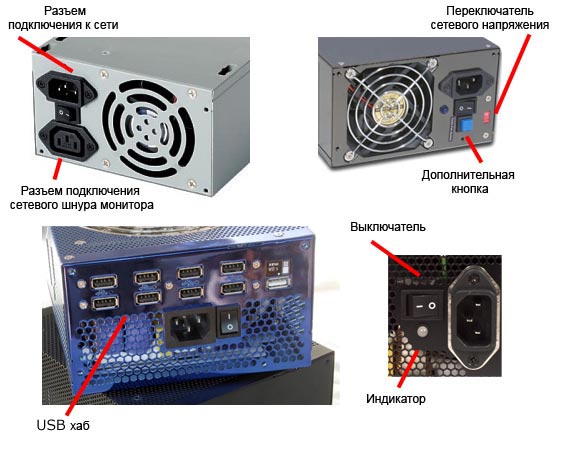
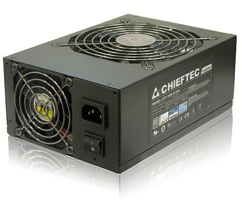
On the rear wall, less and less fans are placed, pulling air from the power supply. The entire fan bowl is placed on top of the power supply due to the larger fan mounting space, allowing for a large and quiet active cooling element. On some power supplies, even two fans are installed both at the top and at the back.
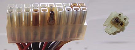
Out of the front wall motherboard power cable. In some power supplies, modular, it, like other wires, is connected through a connector. The figure below shows .
You can see that each voltage has its own wire color:
- Yellow color - +12 V
- Red color - +5 V
- Orange color - + 3.3V
- Black color - common or ground
For other voltages, the colors of the wires for each manufacturer may vary.
The figure does not show the auxiliary power connectors for video cards, since they are similar to the auxiliary power connector for the processor. There are also other types of connectors that are found in brand-name computers from DelL, Apple, and others.

Electrical parameters and characteristics of power supplies
The power supply has many electrical parameters, most of which are not marked in the passport. On the side sticker of the power supply, usually only a few basic parameters are noted - operating voltages and power.
Power supply power
Power is often indicated on the label in large print. The power of the power supply, characterizes how much it can give electrical energy devices connected to it motherboard, video card, hard drive, etc.).
In theory, it is enough to sum up the consumption of the components used and select a power supply unit with a slightly higher power for the reserve. For power counting recommendations given are quite suitable. in the video card passport, if any, CPU thermal package, etc.
But in fact, everything is much more complicated, because the power supply produces different voltages - 12V, 5V, -12V, 3.3V, etc. Each voltage line is designed for its own power. It was logical to think that this power is fixed, and their sum is equal to the power of the power supply. But there is one transformer in the power supply to generate all these voltages used by the computer (except for the standby voltage + 5V). True, it is rare, but you can still find a power supply with two separate transformers, but such power supplies are expensive and are most often used in servers. Ordinary ATX PSUs have one transformer. Because of this, the power of each voltage line can float: it increases if other lines are lightly loaded, and decreases if the other lines are heavily loaded. Therefore, it is often written on power supplies maximum power each line, and as a result, if they are summed up, the power will come out even more than the actual power of the power supply. Thus, the manufacturer can confuse the consumer, for example, by declaring too much rated power, which the PSU is not capable of providing.
Note that if the computer has insufficient power supply, then this will cause incorrect operation of devices ( freezes, reboots, clicks of hard drive heads), up to the impossibility turning on the computer. And if a motherboard is installed in the PC, which is not designed for the power of the components that are installed on it, then the motherboard often functions normally, but over time, the power connectors burn out due to their constant heating and oxidation.
Standards and certificates
When buying a PSU, first of all, you need to look at the availability of certificates and its compliance with modern international standards. On power supplies, you can most often find an indication of the following standards:
There are also computer standards of the ATX form factor, which define the dimensions, design and many other parameters of the power supply, including the permissible voltage deviations under load. Today there are several versions of the ATX standard:
- ATX 1.3 Standard
- ATX 2.0 standard
- ATX 2.2 standard
- ATX 2.3 Standard
The difference between the versions of the ATX standards mainly concerns the introduction of new connectors and new requirements for the power supply lines of the power supply.
Recommendations for choosing a power supply
When does the need to purchase a new power supply ATX, then first you need to determine the power that is needed to power the computer in which this PSU will be installed. To determine it, it is enough to sum up the power of the components used in the system, for example, using a special calculator. If this is not possible, then we can proceed from the rule that for an average computer with one gaming video card, a 500–600 watt power supply is enough.
Given that most of the parameters of power supplies can only be found out by testing it, the next step is strongly recommended to familiarize yourself with the tests and reviews of possible contenders - power supply models, which are available in your area and meet your requirements at least in terms of power provided. If this is not possible, then it is necessary to choose according to the compliance of the power supply with modern standards (the larger the number, the better), while it is desirable to have an AKKM (APFC) circuit in the power supply. When purchasing a power supply, it is also important to turn it on, if possible right at the place of purchase or immediately upon arrival home, and see how it works so that the power supply does not emit squeaks, buzz or other extraneous noise.
In general, you need to choose a power supply that is powerful, well-made, with good declared and actual electrical parameters, and also turns out to be easy to use and quiet during operation, even with a high load on it. And in no case should you save a couple of dollars when buying a power supply. Remember that the stability, reliability and durability of the entire computer mainly depends on the operation of this device.
Add a comment
Write full comments, answers like "thanks for the article" are not published!
We advise you to read
 Therapeutic effect What is vitamin e used for?
 - instructions for use Dexalgin how to take") Dexalgin (ampoules with dexketoprofen) - instructions for use Dexalgin how to take
Dexalgin (ampoules with dexketoprofen) - instructions for use Dexalgin how to take Diclak solution - instructions for use Diclofenac injections instructions for use for children
 Dream Interpretation: why dream of Fire, to see Fire in a dream, which means Why dream of fire in a mirror

