Topic number 4. Three-phase circuits
4.1. Principles of formation of multiphase electrical circuits
A three-phase circuit is a combination of a three-phase EMF system, a three-phase load and connecting wires.
A three-phase symmetrical EMF system is understood as a set of three sinusoidal EMFs of the same frequency and amplitude, shifted in phase by 120 °. The graph of instantaneous values and the vector diagram of the EMF for a symmetrical load are shown in fig. 4.1.a), b).
The three-phase system received the most practical use thanks to the following benefits:
· transmission of energy over long distances by 3-phase current is the most economical;
elements of the system are the simplest in production, economical and reliable in operation;
instantaneous power at the same load in the phases of the generator is unchanged.
b) transmission lines; A three-phase generator consists of a fixed stator and a rotating rotor (Fig. 4.2.). The fixed windings are placed in the slots of the stator, a magnetic field rotates in it, created by a rotating rotor with a wound coil, through which flows alternating current. The generator is synchronous if the angular velocity of the rotor is equal to the angular frequency of the rotating magnetic field stator. A small gap between the stator and the rotor makes it possible to obtain a significant magnetic flux with a small EMF of the rotor winding.When a load is connected to the stator winding, the generator delivers electrical energy to the load.
4.2. Methods for connecting three-phase circuits
There are various schemes for connecting the generator windings to the load. It is possible to connect each winding of the generator to the load with two wires, which would require six wires. In order to save the windings of a three-phase generator and the load, they are connected according to the “star-star” (“triangle”) scheme. In this case, the number of connecting wires from the generator to the load is reduced from six to three or four.
When connecting the "star", the ends of the three windings are combined into one point (Fig. 4.3.), Which is called zero (0). The beginning of the generator windings, indicated by the letters A, B, C, are connected to the load.
When connecting the generator windings with a triangle (Fig. 4.4.b), the end of the first winding is connected to the beginning of the second, the end of the second - to the beginning of the third, the end of the third - to the beginning of the first. The geometric sum of the EMF in a closed triangle is zero. Therefore, if no load is connected to the ABC terminals, then no current flows through the generator windings.
|
A symmetrical three-phase EMF system can be depicted: 1) graphically (Fig. 4.1.); 2) vector diagrams (Fig. 4.2.); 3) trigonometric functions
complex numbers
For a three-phase symmetrical system (Fig. 4.1., 4.2.) Equations are valid
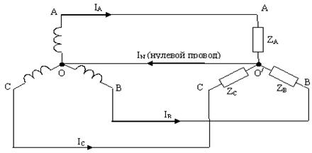
The main connection methods are "star - star" with a neutral wire (Fig. 4.5.), Or without a neutral (neutral) wire N, and "triangle - triangle" (Fig. 4.6.). Connections are also possible: "delta - star" and "star - delta".
Wire connecting zero points O generator and O/ load when connected with a star, is called a neutral or neutral wire, and the current in the neutral wire is called zero current. The positive direction of zero current is taken from O / to O.
The wires connecting points A, B, C of the generator and the load are called linear wires, and the currents flowing through them are called linear I A , I B , I C. The positive direction for them is taken from the generator to the load. Modules of linear currents denote I l.
The voltage between linear wires is called linear and is denoted by two indices, for example, U AB(between points A and B). Linear voltage modulus denote U l.
Each of the three windings of the generator is called the phase of the generator, each of the three loads is called the phase of the load, and the currents flowing through them are the phase currents of the generator and the load I f; and voltage U f they are called phase.
The relationship between line and phase voltages is as follows. When the generator is connected to a star, the line voltage U L = UAB modulo V is greater than the phase voltage of the generator U f .
|
Line current I l when the generator is connected by a star, it is equal to the phase current of the generator .
When connecting the generator into a "triangle", as can be seen from Fig. 4.6. line voltage is equal to the phase voltage of the generator ,
and the line current I l times the phase current .
When connecting the load in a triangle, the positive directions for the currents are chosen clockwise. The first index corresponds to the point from which the current flows, the second - to the point to which it flows. Linear currents are not equal to the load phase currents and are determined through them according to the first Kirchhoff law , ![]() , .
, .
From the vector diagram (Fig. 4.7.) According to the cosine theorem ![]() ,
,
likewise
|
3.3. Calculation of three-phase circuits when connected with a star
To calculate the currents, the circuit diagram, the value and type of resistance, and the voltage of the energy source must be specified. Calculations are usually carried out for complex values.
A symmetrical load in a star-star connection with a neutral wire is shown in fig. 4.8.
If the neutral wire in the circuit of a symmetrical receiver ( ) has a very low resistance (Z 0 \u003d 0), then the potential of the point O / is practically equal to the potential of the point O, and the points merge into one. Three separate circuits are formed in the circuit, the complex values of the currents in each of which are determined as in a single-phase circuit ; ;
where Ė A, Ė B, Ė C- phase voltages at the generator terminals.
According to the first law of Kirchhoff, the current in the neutral wire of 4 wired system equal to the geometric sum of the phase currents ![]() .
.
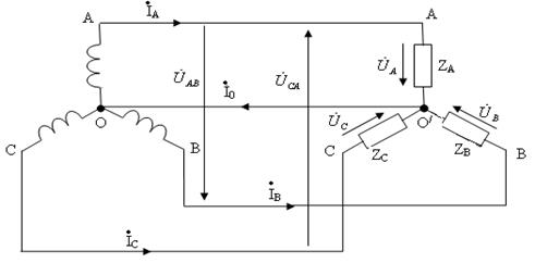
In general, the complex voltage between zero points 0 – 0` with neutral wire
 .
.
With uniform symmetrical load current I 0 =0, and the neutral wire can be removed from the circuit without changing its mode of operation. For a 3-wire system, i.e. not containing a neutral wire (Z N = ∞), the term 1/ Z N will be absent in the denominator.
When determining the voltage of the receiver phases, if the source resistance is not taken into account, then it can be replaced by ![]()
Turning to the effective values of the quantities in the case when the loads in all phases are equal and have an active character ![]() ,
,
where is the value of the linear voltage, the currents, respectively, take the values , , .
The total power of a three-phase circuit with an active load is
 .
.
With an asymmetric load and the absence of a neutral wire, a voltage appears between the zero points of the generator O and the receiver O /, as a result of which the phase voltages of the receiver turn out to be different. The calculated ratio between the phase and linear voltages is violated in this case. To determine the voltage between zero points, as well as the phase voltages of the receiver, assume that there is a neutral (zero) wire in the electrical circuit, the resistance of which is . Then the voltage between the zero points of the source and receiver
where g A , g B , g C , g N- conductivity of phase and neutral wires,
|
On fig. 4.9. a vector diagram without a neutral wire is shown, on which , , are the vectors of the phase voltages of the source, and , , are the vectors of the linear voltages of the source, as well as the linear voltages of the receiver. To plot the stress vector and receiver phase voltage vectors , , we use their values obtained above.
The connection between the phase and linear vectors , , and , , , is determined by the expressions ![]() ,
, ![]() ,
, ![]() .
.
The vector diagram is built for the active unbalanced load of the phases ( ![]() ).
).
When the value of phase active resistances changes, the voltage can vary over a wide range. Accordingly, the point N on the diagram can occupy different positions, and the phase voltages of the receiver can differ quite significantly from each other.
The main current system, currently accepted everywhere, are three-phase, which have a number of advantages over single-phase ones.
A three-phase current is a system of three single-phase currents created by three electromotive forces having the same amplitudes and frequencies, but shifted one relative to the other in phase by 120⁰ or in time by a third of the period.
Each individual circuit of such a three-phase system is abbreviated as a phase.
Thus, the stator of a three-phase current generator has three windings (called generator phases) offset by 120⁰ relative to each other. The rotor of the three-phase current generator is structurally the same as the generator rotor single-phase current.
During the rotation of the rotor in all windings, electromotive forces of the same frequency and amplitude will be created, but only they will not simultaneously reach their maxima. Considering that the maximum electromotive force is created at the moment the center of the rotor passes under the beginning of the winding, it is easy to see that the maximum electromotive force of the same direction in the second winding will come after the rotor rotates by 120⁰, and in the third - after the rotation by 240⁰ relative to the first.
By connecting each phase of the generator with an external circuit, we get three single-phase current circuits that do not have any electrical connections, and the currents in each individual circuit with the same resistance will be equal in amplitude, but also phase shifted relative to each other by 120⁰.
To connect such a generator to an external circuit, six wires are needed. To reduce the number of wires that go to the external circuit, it is necessary to connect the windings of the receivers and the generator to each other, forming an electrically connected three-phase system. Such a connection can be made in two different ways: a triangle and a star.
Both connections make it possible to save material when transmitting the same power from three autonomous three-phase generators.
Three-phase circuits made it possible to create a simple and easy-to-use electric motor, which was called asynchronous. Its device is based on the use of a rotating magnetic field. In the simplest case, such a magnetic field can be obtained by rotating a horseshoe magnet.
If a closed conductor is placed in a rotating field, fixed on an axis, then the magnetic field, during its rotation, crossing the sides of the conductor contour, will induce in them electromotive force induction that creates in this closed circuit. This current, when interacting with the magnetic field of a rotating magnet, will cause the coil to rotate. The direction of rotation of the coil is determined using the left hand rule.
Three-phase electric motors consist of two parts: a rotating part - a rotor and a fixed part - a stator.
A rotating one is created in the motor not by mechanical rotation of the magnetic poles, but by flowing an alternating three-phase current around the stationary stator windings.
Three-phase circuits were developed by one of the outstanding electrical engineers of the 19th and early 20th centuries. - Russian engineer M. O. Dolivo-Dobrovolsky (1862-1919). This system opened the widest possibilities of industrial use. electrical energy. The most important of them:
- savings in the wires of the line connecting the station with the consumer;
- the possibility of obtaining a rotating magnetic field used in three-phase motors.
Connection diagrams for three-phase circuits
A three-phase symmetrical EMF system is understood as a set of three sinusoidal EMFs of the same frequency and amplitude, shifted in phase by 1200.
The graph of their instantaneous values is shown in Fig. 7.1., vector diagram - in fig. 7.2. ![]()
Three-phase emf system. obtained using a three-phase generator, in the grooves of the stator of which three windings are electrically isolated from each other - phase generator windings. The planes of the windings are displaced in space by 1200. When the generator rotor rotates, sinusoidal emfs are induced in the windings. equal in amplitude, but shifted in phase by 1200.
To distinguish three emfs. three-phase generator from each other, they are designated accordingly. If one e.m.f. denote , and leading by 1200 -
On the wiring diagram three-phase generator depicted as three windings located at an angle of 1200 to each other. 
When connected by a "star", the terminals of the same name (for example, the ends) of the three windings are combined into one node, which is called the zero point of the generator and is denoted by the letter 0 (Fig. 7.3). The beginning of the generator windings is denoted by the letters A, B, C.
When connecting the generator windings with a "triangle", the end of the first winding of the generator is connected to the beginning of the second, the end of the second - to the beginning of the third, the end of the third - to the beginning of the first (Fig. 7.4). 
Geometric sum of emf in a triangle is zero. Therefore, if no load is connected to terminals A, B, C, then no current will flow through the generator windings.
The combination of a three-phase EMF system and a three-phase load (or loads and connecting wires) is called three-phase circuit.
The currents flowing through individual sections of a three-phase circuit are shifted relative to each other in phase. Under phase A three-phase circuit is understood as a section of the circuit through which the same current flows. Thus, depending on the issue under consideration, a phase is either a section of a three-phase circuit, or an argument of a sinusoidally changing quantity. The three windings of the generator must be connected to the load. Exist various ways winding connections. The most uneconomical way would be to connect each winding of the generator to the load with two wires, which would require six connecting wires. In order to save money, the windings of a three-phase generator are connected into a "star" or "triangle", as a result of which the number of connecting wires from the generator to the load is reduced from six to three or to four.
Consider ways to connect a three-phase generator to a three-phase load.
The connection diagram "star" - "star" with a neutral wire is shown in fig. 7.5.
The node that forms the three ends of a three-phase load when connected by a "star" is called the zero point of the load and is denoted 0 ". 
The wire connecting the zero points of the generator and the load is called zero (neutral). The current of the neutral wire is denoted by I0, the positive direction of the current is from node 0 "to node 0. The wires connecting the terminals A, B, C of the generator with the load are called linear wires. The currents flowing through the linear wires are called linear, they are denoted IA, IB, IC Let's agree for the positive direction for them to take the direction from the generator to the load.Linear current modules are often designated IL without indicating any additional index.This designation is often used when line currents modulo are the same. The voltage between the line wires is called line voltage and is denoted by two indices, for example UAB. The linear voltage module is designated UL.
Each of the three windings of a generator is called a generator phase. Each of the three loads is called a load phase. The currents flowing through them are called phase currents IF, and the voltages on them are called phase or phase voltages UФ.
The circuit in Fig. 7.6 is called "star - star" without a neutral wire; in Fig.7.7. - "star - triangle"; in fig. 7.8. - "triangle - triangle", in fig. 7.9. - "triangle - star". 
Depending on the order of connections, the following are distinguished: types of circuit connections:
1. Series connection.
2. Parallel connected connection.
3. Connection in the form of a "polygon".
4. Connection in the form of a "star".
Let us analyze the features of these types of chain connections.
Distinctive characteristic serial connection chains is that it has no intermediate nodes. In addition, the same current flows in all elements of such a connection. For clarity, we have shown an example of such a connection in the figure below.
The result of a series connection is the summation of the voltage across the elements. So, for example, according to the scheme shown in the figure above:
It should be noted that the voltage is directed opposite to the direction of the current, since, in accordance with the direction of the arrow of the source, its positive terminal is on the right, and the negative terminal is on the left. The voltage has a constant direction from plus to minus.
As well as voltages, resistances with this type of connection add up. It is convenient to clearly demonstrate this using the example of a series connection in a circuit. direct current, where
Main characteristic parallel connection is that the same voltage is applied to all branches connected in parallel. The figure below shows an example of a parallel connection.
In the case of a parallel connection of circuits, the voltages in its branches are summed up. This can be seen in the diagram example above.
![]()
The equivalent resistance in parallel connection of the branches is found by searching for the equivalent conductivity of the circuit. The equivalent conductance of the circuits is equal to the sum of the conductance of the branches. Conductivity is the reciprocal of resistance. The unit of conductivity is Siemens (cm). For ease of understanding, we will give an example of a parallel connection in a DC circuit.
Polygon chain connection there are several types. The simplest of them is the triangle. You can see it in Figure 26.
There is only one series connection of circuits in this figure. This is the resistance R1 and EMF E1. At the same time, several "triangle" type connections can be distinguished. So, the resistances R2, R4, R5 form the sides of the "triangle" with the vertices A, B, D. The resistances R3, R4, R6 form the sides of the "triangle" with the vertices B, C, D. The branch R1 and E1 and the branches R2, R3 also are the sides of the triangle. Its vertices are A, B, C. A star connection can be formed from a triangle connection.
In the same diagram of Figure 26, star connections can be distinguished. So, the resistances R2, R3, R4 are "star" rays converging at node B. The star rays R4, R5, R6 converge at node D. Accordingly, the connection of the "star" circuits can be transformed into an equivalent delta connection.
The development of multiphase systems has been driven historically. Research in this area was caused by the requirements of developing production, and success in the development of multiphase systems was facilitated by discoveries in the physics of electrical and magnetic phenomena.
The most important prerequisite for the development of multi-phase electrical systems was the discovery of the phenomenon of a rotating magnetic field (G. Ferraris and N. Tesla, 1888). The first electric motors were two-phase, but they had low performance. The three-phase system turned out to be the most rational and promising, the main advantages of which will be discussed below. A great contribution to the development of three-phase systems was made by the outstanding Russian electrical engineer M.O.
The source of three-phase voltage is a three-phase generator, on the stator of which (see Fig. 1) is placed three-phase winding. The phases of this winding are arranged in such a way that their magnetic axes are shifted in space relative to each other by el. glad. On fig. 1, each stator phase is conventionally shown as a single turn. The beginning of the windings is usually denoted by capital letters letters A, B, C, and the ends are respectively capitalized x, y, z. EMF in the fixed stator windings is induced as a result of crossing their turns by a magnetic field created by the current of the rotating rotor excitation winding (in Fig. 1, the rotor is conventionally shown as a permanent magnet, which is used in practice at relatively low powers). When the rotor rotates at a uniform speed, periodically changing sinusoidal EMFs of the same frequency and amplitude are induced in the windings of the stator phases, but differ due to a spatial shift from each other in phase by rad. (see Fig. 2).
Three-phase systems are currently the most widely used. All large power plants and consumers operate on three-phase current, which is associated with a number of advantages of three-phase circuits over single-phase ones, the most important of which are:
Cost-effective transmission of electricity over long distances;
The most reliable and economical, meeting the requirements of an industrial electric drive, is an asynchronous motor with a squirrel-cage rotor;
The possibility of obtaining a rotating magnetic field using fixed windings, on which the operation of synchronous and induction motors, as well as a number of other electrical devices;
Balance of symmetrical three-phase systems.
To consider the most important balance properties three-phase system, which will be proved below, we introduce the concept of symmetry of a multi-phase system.
The EMF system (voltages, currents, etc.) is called symmetrical if it consists of m equal modulo EMF vectors (voltages, currents, etc.) shifted in phase relative to each other by the same angle. In particular, the vector diagram for a symmetrical EMF system corresponding to a three-phase system of sinusoids in fig. 2 is shown in fig. 3.
 |
|
| Fig.3 | Fig.4 |
Of the asymmetric systems, the two-phase system with a 90-degree phase shift is of the greatest practical interest (see Fig. 4).
All symmetrical three- and m-phase (m>3) systems, as well as a two-phase system, are balanced. This means that although in individual phases the instantaneous power pulsates (see Fig. 5, a), changing during one period not only the value, but in the general case also the sign, the total instantaneous power of all phases remains constant during the entire period of the sinusoidal EMF (see Fig. 5,b).
Balance is of the utmost practical importance. If the total instantaneous power were to pulsate, then a pulsating torque would act on the shaft between the turbine and the generator. Such a variable mechanical load would have a detrimental effect on the power generating plant, reducing its service life. The same considerations apply to polyphase motors.
If the symmetry is broken (the two-phase Tesla system, due to its specificity, is not taken into account), then the balance is also broken. Therefore, in the energy sector, they strictly monitor that the load of the generator remains symmetrical.
Connection diagrams for three-phase systems
A three-phase generator (transformer) has three output windings, identical in number of turns, but developing EMF, shifted in phase by 1200. A system could be used in which the phases of the generator winding would not be galvanically connected to each other. This so-called disconnected system. In this case, each phase of the generator must be connected to the receiver with two wires, i.e. there will be a six-wire line, which is uneconomical. In this regard, such systems have not received wide application on practice.
To reduce the number of wires in the line, the phases of the generator are galvanically connected to each other. There are two types of connections: into a star and into a triangle. In turn, when connected to a star, the system can be three- and four-wire.
star connection
On fig. 6 shows a three-phase system when connecting the phases of the generator and the load into a star. Here the wires AA', BB' and CC' are line wires.
Linear called the wire connecting the beginning of the phases of the winding of the generator and receiver. The point at which the ends of the phases are connected to a common node is called neutral(in Fig. 6, N and N' are the neutral points of the generator and the load, respectively).
The wire connecting the neutral points of the generator and receiver is called neutral(shown in dotted line in Fig. 6). A three-phase system when connected to a star without a neutral wire is called three-wire, with neutral wire four-wire.
All quantities related to phases are called phase variables, to the line linear. As can be seen from the diagram in Fig. 6, when connected to a star, the line currents and are equal to the corresponding phase currents. If there is a neutral wire, the current in the neutral wire ![]() . If the system of phase currents is symmetrical, then . Therefore, if the symmetry of the currents were guaranteed, then the neutral wire would not be needed. As will be shown below, the neutral wire maintains the symmetry of the voltages on the load when the load itself is unbalanced.
. If the system of phase currents is symmetrical, then . Therefore, if the symmetry of the currents were guaranteed, then the neutral wire would not be needed. As will be shown below, the neutral wire maintains the symmetry of the voltages on the load when the load itself is unbalanced.
(its initial phase is zero), we count the phase shifts of the linear voltages with respect to this axis, and their modules are determined in accordance with (4). So for linear voltages and in a triangle current will flow short circuit. Therefore, for a triangle, it is necessary to strictly observe the order of connecting phases: the beginning of one phase is connected to the end of another.
The connection diagram of the generator and receiver phases in a triangle is shown in fig. 9.
Obviously, when connected in a triangle line voltages equal to the corresponding phase. According to the first Kirchhoff law, the relationship between the linear and phase currents of the receiver is determined by the relations
![]()
Similarly, linear currents can be expressed in terms of phase currents generator.
On fig. 10 shows a vector diagram of a symmetrical system of linear and phase currents. Its analysis shows that with the symmetry of the currents
| . | (5) |
In conclusion, we note that in addition to the star-star and triangle-delta connections considered, the star-triangle and triangle-star schemes are also used in practice.
Literature
- Basics circuit theory: Proc. for universities /G.V.Zeveke, P.A.Ionkin, A.V.Netushil, S.V.Strakhov. –5th ed., revised. -M.: Energoatomizdat, 1989. -528s.
- Bessonov L.A. Theoretical basis electrical engineering: Electrical circuits. Proc. for students of electrical, energy and instrument-making specialties of universities. –7th ed., revised. and additional –M.: Higher. school, 1978. -528s.


