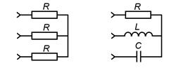
A polyphase receiver and, in general, a polyphase circuit are called symmetrical if the complex resistances of the corresponding phases are the same in them, i.e. If . Otherwise, they are asymmetrical. The equality of the modules of the indicated resistances is not a sufficient condition for the symmetry of the circuit. So, for example, the three-phase receiver in Fig. 1a is symmetrical, and in Fig. 1, b - no, even under the condition: ![]() .
.

When analyzing complex circuits operating in a symmetrical mode, the calculation is carried out using the following basic techniques:
All triangles are replaced by equivalent stars. Since the triangles are symmetrical, then in accordance with the triangle-star transformation formulas.
Since all the original and newly received load stars are symmetrical, the potentials of their neutral points are the same. Therefore, without changing the mode of operation of the circuit, they can (mentally) be connected with a neutral wire. After that, the basic phase (usually phase A) is separated from the circuit, for which the calculation is carried out, the results of which determine the corresponding values in other phases.
29) Emergency modes in three-phase circuits.
To connect a three-phase circuit to a star, the following emergency modes of operation are possible:
1) phase break (Fig. 3.10);
2) breakage of the neutral wire (Fig. 3.11);
3) short circuit of the phase when zero breaks (Fig. 3.12).
4) phase loss and zero, fig. 3.12.
34) Errors of electrical measuring instruments.
The errors of electrical measuring instruments are divided into basic and additional. The main error characterizes the quality of the device under normal operating conditions and under normal external conditions.
Additional errors due to deviations external factors and operating conditions from normal. The name of the accuracy class numerically determines the permissible basic error.
26) Power factor improvement in electrical circuit.
The power factor of an electrical circuit is the ratio of the active power of the circuit to the total, i.e.
Power Factor Improvement Methods
1. timely shutdown of electric motors and transformers running idle (they have = 0.2 ... 0.5);
2. for asynchronous motors operating with a small load, switching the stator winding from a triangle to a star. In this case, the no-load current decreases by 3 times (see Examples 6.93 and 6.94);
3. inclusion in the network of reactive power compensators of two types:
a) capacitor, in the form of batteries of large capacitors.
b) synchronous, which are synchronous generators operating without active load.
In both cases, the principle of increasing the power factor is the same: the capacitor feeds the network with reactive capacitive current, which, being in antiphase with the inductive load current, compensates it completely or partially.
As a result, the current in the closed circuit: generator - transmission line - power receiver - generator, decreases.
Before connecting the capacitor, a current flowed through the coil, which lagged behind the voltage by an angle. The reactive inductive component of this current is indicated on the diagram as .
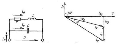
Rice. 6.64. Scheme and vector diagram of the currents of the capacitor reactive power compensator
Three-phase circuit operating modes
There are symmetrical, asymmetric and emergency modes of operation of a three-phase circuit.
A three-phase circuit is symmetrical if the complex resistances of all three phases in it are the same, i.e. If . Otherwise, they are asymmetrical. The equality of the modules of the indicated resistances is not a sufficient condition for the symmetry of the circuit. So, for example, a three-phase receiver connected by a star, in fig. 2.18, A is symmetrical, and in Fig. 2.18, b No, even if: R = Z L = Z C.
If a symmetrical three-phase generator voltage system (2.35) is applied to a symmetrical three-phase load, then a symmetrical system of currents will take place in it. This mode of operation of a three-phase circuit is called symmetrical. In this mode, the currents and voltages of the corresponding phases are equal in absolute value and are phase-shifted with respect to each other by an angle of 2π/3. If in a three-phase system with a symmetrical three-phase generator voltage system the load is asymmetric, then there will be asymmetrical operating mode of a three-phase circuit.
 |
|
| A) | b) |
| Rice. 2.18 - Load examples |
When calculating a three-phase circuit in a symmetrical mode of operation, its calculation is carried out first for one phase (Figure 2.14), for example, a phase A, according to the results of which the corresponding values, currents and voltages, are determined in other phases. These voltages and currents will be equal in magnitude. The phase shift angles will also be the same. Neutral current I 0 will be zero and the voltage between the points Nn (Un - neutral bias voltage) will also be zero.
In unbalanced mode, these calculations must be made for each phase separately. In this mode, due to the inequality of currents (their modules and arguments), a current will appear I0 ≠ 0.
To connect a three-phase circuit to a star, the following are possible: emergency operating modes:
1) breakage of one of the phases;
2) breakage of the neutral wire;
3) phase failure and zero;
4) short circuit of the phase when the neutral wire breaks.
At one phase break, work is not performed by the load of this phase, and the rest of the loads will not change their operating modes. In this case, the neutral wire will be loaded additionally.
If the loads are connected and are one, then this mode will be emergency. For example, if the load is asynchronous motor, then it will be in emergency mode and the neutral wire will be loaded.
Break of the neutral wire does not always cause an accident in three-phase circuits. If the load is symmetrical, then a break in the neutral wire will not change the load currents, since for a symmetrical load I0 = 0. For unbalanced loads I 0 ≠ 0, and therefore this mode can cause an accident.
Phase failure and neutral wire leads to I 0 = 0 and to the disappearance of one phase voltage. The consumers of the remaining phases are connected in series. The currents in these phases will be the same, and the voltages on them will depend on the load resistances.
To connect a three-phase circuit to a star, the following emergency modes of operation are possible:
1) phase break (Fig. 3.10);
2) breakage of the neutral wire (Fig. 3.11);
3) short circuit of the phase when zero breaks (Fig. 3.12).
4) phase loss and zero, fig. 3.12.
To connect a three-phase circuit into a triangle, the following emergency modes are possible:
1) phase failure;
2) line wire break.
1) When phase A breaks, no work is done by the load, and the rest of the loads () will not change their operating modes 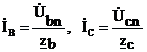 .
.
If the loads are connected and is one whole, then this mode will be emergency. So, if this load is an asynchronous motor, then it will be in emergency mode and the neutral wire will be loaded additionally
2) A break in the neutral wire does not always cause an accident in three-phase circuits. If the load is symmetrical, then a break in the neutral wire will not change the load currents, since for a symmetrical load
For unbalanced loads, and therefore this mode can cause an accident.
To show this, we use the two node method:
The voltage is not zero if the loads are unbalanced. Phase currents will also be unequal.
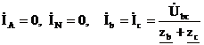
3) With a short circuit of phase A and a break in zero, the voltage of this phase is zero:,
 .
.
Similarly, in phase C:
 ;
;
Will be increased in relation to the original in times.
4) Loss of phase and neutral wire gives:
 .
.
In the remaining phases, the currents will be the same, and the voltages on them will depend on the load resistances (Fig. 3.16).
1) Phase failure.
Key k1 is closed, key k2 is open (Fig. 3.17). In this mode, there is no current in the phase, and the rest of the loads work as usual (Fig. 3.18). In such an emergency mode, the linear currents of phases A and B correspond to the phase currents, and line current phase C remains as it was before.
2) Line wire break. Key k1 is open and key k2 is closed (Fig. 3.19). The load phase will not change from its mode, and the phases become connected in series and connected in parallel to the linear voltage of phases B, C (see Fig. 3.17), that is, the circuit becomes single-phase. Topographic and vector diagrams in this case may look like shown in Fig. 3.19.
18. Active, reactive, apparent power of a three-phase system; active power measurement
The active power of a three-phase system is the sum of the active powers of all phases of the energy source, which is equal to the sum of the active powers of all phases of the receiver.
In a symmetrical three-phase system, i.e. system with a symmetrical generator and receiver, for any scheme of their connections for each phase, the power of the receiver's energy source is the same. In this case, and for each of the phases, the formula for the active power of a sinusoidal current is valid.
By clicking on the "Download archive" button, you will download the file you need for free.
Before downloading this file, remember those good essays, control, term papers, theses, articles and other documents that lie unclaimed on your computer. This is your work, it should participate in the development of society and benefit people. Find these works and send them to the knowledge base.
We and all students, graduate students, young scientists who use the knowledge base in their studies and work will be very grateful to you.
To download an archive with a document, enter a five-digit number in the field below and click the "Download archive" button
Similar Documents
 How to install an aluminum sliding balcony frame with your own hands - installation technology Installation of sliding windows on the balcony with your own hands
 How to connect an electromechanical lock to a video intercom?
 Do-it-yourself door limiter: stopper made of wood, fabric
 We select and install latches on interior doors
The main elements of three-phase electrical circuits, as well as the voltage between the phase terminals. Analysis of electrical circuits when connecting a three-phase source and receiver according to the "star" scheme with a neutral wire. Receiver connection according to the "triangle" scheme.
presentation, added 09/22/2013
The main elements of three-phase electrical circuits. Three-phase source electrical energy. Analysis of electrical circuits when connecting a three-phase source and receiver according to the "star" with a neutral wire and "triangle" schemes. Calculation and measurement of power.
presentation, added 07/25/2013
Features of the connection of the energy source and the receiver according to the star and delta scheme. Active, reactive and apparent power of a three-phase symmetrical system. Symmetrical three-phase circuit with multiple receivers. Unbalanced three-phase circuit.
term paper, added 12/15/2010
Features of the "star" type connection, the procedure for designing and manufacturing a replaceable module for laboratory work on its study. The concept of quadripoles and the procedure for determining the modes of their operation, the methodology for calculating special coefficients.
term paper, added 11/21/2009
The study of the features of the connection of the phases of the receivers according to the "star" scheme. Experimental study of the distributions of currents, linear and phase voltages for symmetrical and asymmetrical modes of operation of a three-phase circuit. Finding out the role of the neutral wire in the circuit.
laboratory work, added 11/22/2010
Equivalent transformations of an electric circuit with resistor elements into a circuit with Re. serial connection elements. Equivalent conversion of delta to star connections and vice versa. Calculation of a scheme related to a mixed connection.
term paper, added 06/01/2014
Safety requirements. Three-phase circuit when connecting consumers according to the "star" and "triangle" schemes. Single-phase electricity meter. Transformer no-load experience, short circuit. The operation of a fluorescent lamp.

