Beginners who are trying to assemble some electronic circuits and devices on their own face the very first question in their new activity, how to read electrical circuits? The question is actually a serious one, because before you assemble the circuit, it must be somehow marked on paper. Or find a ready-made option for implementation. That is, reading electrical circuits is the main task of any radio amateur or electrician.
What is an electrical circuit
This is a graphic image, which shows all the electronic elements interconnected by conductors. Therefore, knowledge of electrical circuits is the key to a properly assembled electronic device. And, therefore, the main task of the assembler is to know how the electronic components are indicated on the diagram, what graphic icons and additional alphabetic or numeric values.
All circuit diagrams consist of electronic elements that have a conventional graphic designation, in short RCD.
For example, let's give some of the simplest elements that are very similar to the original in graphic design. This is how the resistor is designated:

As you can see, it is very similar to the original. And here is the speaker:
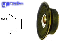
The same great similarity. That is, there are some positions that can be immediately identified. And it's very convenient. But there are also completely dissimilar positions that either need to be remembered, or you need to know their designs in order to easily determine them on a circuit diagram. For example, the capacitor in the figure below.

Anyone who has long been versed in electrical engineering knows that a capacitor is two plates, between which a dielectric is placed. Therefore, this icon was chosen in the graphic image, it exactly repeats the design of the element itself.
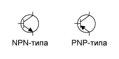
The most complex icons for semiconductor elements. Let's take a look at the transistor. It should be noted that this device has three outputs: emitter, base and collector. But that's not all. Bipolar transistors have two structures: "n - p - n" and "p - n - p". Therefore, they are also indicated differently in the diagram:
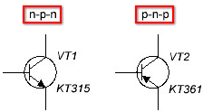
As you can see, the transistor does not look like it in its image. Although, if you know the structure of the element itself, then you can figure out that this is exactly what it is.
Simple diagrams for beginners, knowing a few icons, can be read without problems. But practice shows that simple electrical circuits in modern electronic devices are practically not dispensed with. So you have to learn everything related to circuit diagrams. And, therefore, it is necessary to deal not only with icons, but also with alphabetic and numeric designations.
What do letters and numbers mean
All numbers and letters in the diagrams are additional information, this is again the question of how to read wiring diagrams correctly? Let's start with letters. A Latin letter is always affixed next to each RCD. Essentially, this letter designation element. This was done on purpose so that when describing a circuit or device of an electronic device, its details could be indicated. That is, do not write that it is a resistor or a capacitor, but put a symbol. It's both easier and more convenient.
Now the numeric designation. It is clear that in any electronic circuit there will always be elements of the same value, that is, of the same type. Therefore, each such detail is numbered. And all this digital numbering goes from the upper left corner of the diagram, then down, then up and down again.
Attention! Experts call this numbering the “AND” rule. If you pay attention, then the movement according to the scheme is exactly what happens.
![]()
And the last. All electronic elements have certain parameters. They are usually also written next to the icon or placed in a separate table. For example, next to the capacitor, its nominal capacitance in micro- or picofarads, as well as its nominal voltage (if such a need arises), can be indicated. In general, everything related to semiconductor parts must be supplemented with information. This not only makes it easier to read the diagram, but also allows you not to make mistakes when choosing the element itself during the assembly process.
Sometimes there are no digital symbols on the wiring diagrams. What does it mean? For example, take a resistor. This suggests that in this electrical circuit the indicator of its power does not matter. That is, you can install even the most low-power option that will withstand the load of the circuit, because a low current flows in it.
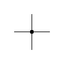
And a few more notations. Conductors are graphically indicated by a straight continuous line, solder points by a dot. But keep in mind that the point is placed only in the place where three or more conductors are connected.
Conclusion on the topic
So, the question of how to learn to read electrical circuits is not the easiest. You will need not only knowledge of the RCD, but also knowledge regarding the parameters of each element, its structure and design, as well as the principle of operation, and why it is needed. That is, you will have to learn all the basics of radio and electrical engineering. Difficult? Not without it. But if you understand how everything works, then horizons will open for you that you never dreamed of.
Related posts: 
Instruction
When studying the fundamental scheme determine the poles electrical circuit and set the current direction - from "plus" to "minus". Identify the components of the circuit: contacts, resistors, diodes, capacitors and other elements included in the circuit. If the circuit contains several circuits, they should be read one at a time, considering each one in sequence.
At the beginning of reading the circuit, determine all the power supply systems included in the circuit. Find a source of energy, relays, electromagnets, if any. Determine the type of all sources, the current used (direct or alternating), its phase or polarity.
When studying a circuit, you need to have an idea of the operation of each element of the circuit separately, starting with the simplest components. A resistor is a passive element of an electrical circuit and is intended, as a rule, for power dissipation, voltage drop. In diagrams, it is used to indicate the resistance function and is displayed as a rectangle. A capacitor, on the other hand, accumulates electrical energy alternating current, its sign is two parallel lines.
Read all the explanations and notes given on the diagram. If there are electric motors or other electrical receivers in the device, analyze them. Consider all the circuits of these elements from one pole of the power source to the other. Notice in these circuits the location of resistors, diodes, capacitors and other components of the circuit. Make a conclusion about the practical significance of each element of the circuit and about the malfunction of the electrical device when any part of its circuit is blocked or missing.
Specify the location of protective devices: overcurrent relays, fuses and automatic regulators, as well as switching elements. On the circuit diagram of the electrical device, inscriptions can be indicated indicating the protection zones of each of the elements, find them and compare them with other circuit data.
The main purpose of the fundamental electronic scheme in order to reflect with sufficient clarity and completeness the mutual relations between the individual elements of the device (device). The circuit diagram is used to study automation systems, the production of electronic equipment and its proper operation. Ability to read similar scheme allows you to understand the principle of operation of the system and make additions, clarifications or changes to it, if necessary.
Instruction
Start reading the principle scheme with a general acquaintance with it and with the list of elements included in the structure of the product. Find each of the elements on the diagram, understand their relative position. Also read all the explanations and notes that are attached to the electronic circuit.
Determine the power supply system, windings of magnetic starters, relays and electromagnets (if any) according to the diagram. Find all power sources and determine the type of current for each of them, voltage parameters, phasing (in AC circuits) and polarity (in circuits direct current). Compare the data obtained with the nominal data of the equipment indicated in the technical documentation.
Find the switching elements and protection devices according to the diagram. These include fuses, circuit breakers, overcurrent relays, and so on. According to the inscriptions on the schematic diagram, notes and tables attached to the diagram, determine the protection zone for each of these elements.
Study the circuits of electrical receivers (electric motor, magnetic starter windings, etc.). Start targeted analysis with the main electrical receiver, which is usually an electric motor (if present in the product). Trace all the circuits of this element from one pole to another. Mark for yourself all the contacts, resistors and diodes included in the power receiver circuit.
Evaluate the purpose of each of the considered elements. In this case, it is convenient to proceed from the assumption that this element (resistor, diode, capacitor) is absent in the circuit, asking the question: “What consequences will the removal from scheme this element?
When reading an electronic circuit, always proceed from the goal that is in front of you. Usually the study of fundamental scheme aims to identify errors in the installation, determine the possible causes of device failure, identify elements that can cause failures in the system.
If you come across sheets with incomprehensible dashes, rhombuses and other letters that remind an ignorant person of Egyptian tablets, get ready - these are electrical circuits.
Note that such things rarely fall into the hands of ignorant people. In order to learn how to read electrical circuits, it is not enough just to understand. At a minimum, you need to purchase or download a book on microcircuitry from the network. Alternatively, you can call a knowledgeable person to tell at least about the purpose of the main nodes and common designations.
Much easier to deal with circuit diagrams. However, this type of scheme gives an idea only about the principle of operation, and not about a specific version of the laying and the location of certain elements.
The main elements are easy to recognize.
- All wires are marked with simple lines.
- Connection points are indicated by dots.
- Small rectangles are resistors.
- A circle with a cross, these are light bulbs or LEDs.
- The circle and another one inside it, most often means the engine.
- The keys are the places where the wire line opens and, as it were, deviates to the side.
- Relays are represented by rectangles with a U-shaped pattern.
In general, electrical literacy is quite complex and has complex specifics. Even if you understand all the elements and the principles of their application to the circuit, it will still be difficult to read electrical circuits. The main task is not just to understand what is shown in the diagram, but how all these elements interact with each other. Unfortunately, reading circuits is tied not only to microcircuitry, but also to electricians in general. In addition, each scheme has a direction depending on the scheme of what lies in front of you.
Related videos
When we pass tests and receive a piece of paper with the results, we are all trying to understand what is hidden behind these numbers. And we don't understand anything. But as soon as the attending physician looks at the result, everything immediately becomes clear to him. And he announces: "You are healthy" or "You are sick." But learning to "read" the analyzes on your own is easy.

Instruction
On the extract next to the resulting value is the value of the norm. Let's see if our result fits into this framework. If it fits, then you are healthy. If you have an inflammatory process in your body, then leukocytes or the erythrocyte sedimentation rate (ESR) will be increased. With anemia, the hemoglobin and red blood cells will be reduced. If platelets rise, this is a sign of blood diseases. And if there are more than 5% of eosonophils in the body, this means that the patient has an allergy.
But it may be that the result will be within the normal range, but is either closer to the first value or to the second. And then this means that something in your body is either slightly lacking in the lower limit of the norm, or there is too much in the upper limit. It is these indicators that can be adjusted to prevent the development of the disease.
The parameters of the general analysis of urine may indicate urological diseases (elevated leukocytes in the analysis will inform you about this). These include: pyelonephritis, cystitis, nephritis, renal failure.
The appearance of glucose in the analysis indicates the presence of diabetes mellitus.
By the color of urine, if it is dark in color, similar to thickly brewed tea, liver diseases can be determined. After all, it is the "extra" bilirubin that stains the urine in such a color. Urolithiasis in a urinalysis is indicated by the appearance of calcium. Blood in the urine may indicate the presence of a bladder tumor.

Related videos
The circuit diagram of the device is designed to fully and clearly reflect the connections between the elements of the device. It can also be used to study automated systems management. Without the ability to understand electrical circuits, it is impossible to understand the principle of operation of a device and make the required changes to it.

Instruction
Familiarize yourself with the diagram and the list of elements that make up the structure attached to it technical system. Find each of the components on a schematic image, note for yourself their relative position. If text explanations are attached to the diagram, also study them.
Start learning scheme and definitions of the power supply system. It includes a source of energy, windings of magnetic starters, relays and electromagnets, if any are provided for by the circuit. For each power source, determine its type, type of current used, phasing or polarity (depending on whether the device uses AC or DC). Check if the parameters of the electronic devices correspond to the nominal data specified in technical description devices.
Determine where the switching elements and protective devices are located. These are overcurrent relays, fuses and automatic regulators. Using the inscriptions on the electrical diagram, find the protection zones for each of these elements.
If there are electrical receivers in the device, for example, an electric motor, starter windings, and so on, analyze them. Trace all the circuits of the indicated elements from one pole of the power source to another. Note the location of the diodes and resistors in these circuits.
Each of the elements of the chain has its own purpose, which you must establish. At the same time, proceed from the assumption that one or another resistor, capacitor or diode is absent in the circuit. What will be the consequences of this? Such a conditional sequential exclusion of elements from scheme guide you to set the function of each individual appliance.
When studying the circuit diagram, always keep in mind what the goal is in front of you. Most often reading scheme is required to clarify the purpose of the entire device, to make improvements to its operation. Often, a circuit diagram allows you to identify installation errors and establish possible causes of a malfunction of an electrical device due to the failure of its elements.
In connection with the active introduction of automation systems at enterprises, schemes that include electric drives are widespread. The process of installation and adjustment of electrical installations requires the ability to understand the circuit diagrams and wiring diagrams of devices. This requires skill and some practice.
Instruction
Find out for yourself general principles building circuits that include an electrical installation. The basis of the system is any mechanism (machine, engine, ballasts, and so on). For a conditional image of the elements of the system, use different kinds schemes: hydraulic, pneumatic, kinematic, electric and combined. For a better understanding of the electrical circuit, study all the other options for the images attached to it.
"How to read electrical diagrams?". Perhaps this is the most frequently asked question in Runet. If in order to learn to read and write, we studied the alphabet, then here it is almost the same. To learn how to read circuits, first of all, we must study what a particular radio element looks like in a circuit. In principle, there is nothing complicated about this. The whole point is that if there are 33 letters in the Russian alphabet, then in order to learn the designations of radio elements, you will have to try hard. Until now, the whole world cannot agree on how to designate this or that radio element or device. Therefore, keep this in mind when you collect bourgeois schemes. In our article, we will consider our GOST version of the designation of radio elements.
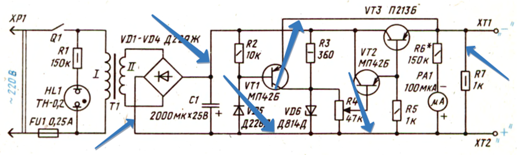
Okay, more to the point. Let's look at a simple electrical circuit of the power supply, which used to flash in any Soviet paper publication:
If you have been holding a soldering iron in your hands for more than a day, then everything will immediately become clear to you at a glance. But among my readers there are those who are faced with such drawings for the first time. Therefore, this article is mainly for them.
Well, let's analyze it.
Basically, all diagrams are read from left to right, just like you read a book. Any different scheme can be represented as a separate block, to which we supply something and from which we remove something. Here we have a power supply circuit, to which we supply 220 volts from the outlet of your house, and a constant voltage comes out from our block. That is, you must understand what is the main function of your circuit. You can read it in the description for it.
So, it seems that we have decided on the task of this scheme. Straight lines are wires along which electric current will run. Their task is to connect radio elements.
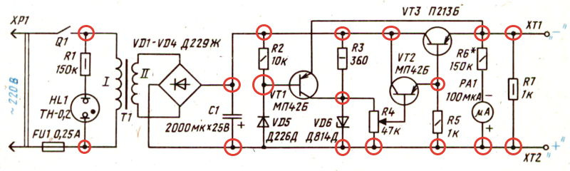
The point where three or more wires join is called node. We can say that in this place the wires are soldered:
If you look closely at the circuit, you can see the intersection of two wires
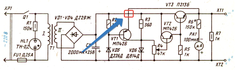
Such an intersection will often flash in the diagrams. Remember once and for all: at this point the wires do not connect and they must be isolated from each other. In modern circuits, you can most often see this option, which already visually shows that there is no connection between them:
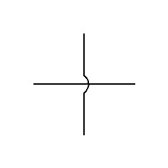
Here, as it were, one wire goes around the other from above, and they do not contact each other in any way.
If there was a connection between them, then we would see this picture:
Let's take a look at our diagram again.
As you can see, the scheme consists of some obscure icons. Let's take a look at one of them. Let it be the R2 icon.
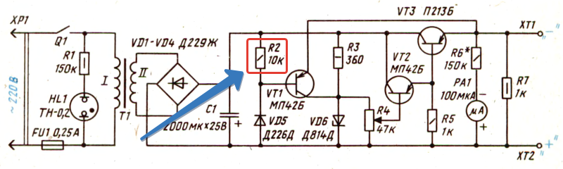
So, let's deal with the inscriptions first. R stands for resistor. Since he is not the only one in our scheme, the developer of this scheme gave him the serial number "2". There are 7 of them in the scheme. Radio elements are generally numbered from left to right and top to bottom. A rectangle with a dash inside already clearly shows that this is a fixed resistor with a power dissipation of 0.25 watts. Also next to it is written 10K, which means its face value is 10 KiloOhm. Well, something like this...
How are the other radioelements designated?
To designate radio elements, single-letter and multi-letter codes are used. Single letter codes are Group to which the element belongs. Here are the main groups of radio elements:
BUT - these are various devices (for example, amplifiers)
AT - converters of non-electric quantities into electrical ones and vice versa. This may include various microphones, piezoelectric elements, speakers, etc. Generators and power supplies here do not apply.
FROM - capacitors
D - integrated circuits and various modules
E - different elements that do not fall into any group
F - arresters, fuses, protective devices
H - indicating and signaling devices, for example, sound and light indication devices
U - converters of electrical quantities into electrical, communication devices
V - semiconductor devices
W - microwave lines and elements, antennas
X - contact connections
Y - mechanical devices with electromagnetic drive
Z - terminal devices, filters, limiters
To clarify the element, after the one-letter code comes the second letter, which already means element type. Below are the main types of elements along with the group letter:
BD - ionizing radiation detector
BE - synchro-receiver
BL - photocell
BQ - piezoelectric element
BR - speed sensor
BS - pickup
BV - speed sensor
BA - loudspeaker
BB - magnetostrictive element
BK - thermal sensor
BM - microphone
BP - pressure meter
BC - selsyn sensor
DA - integrated analog circuit
DD - integrated digital circuit, logic element
D.S. - information storage device
DT - delay device
EL - lighting lamp
EK - heating element
FA - instantaneous current protection element
FP - current protection element of inertial action
FU - fuse
FV - voltage protection element
GB - battery
HG - symbolic indicator
HL - light signaling device
HA - sound alarm device
KV - voltage relay
KA - current relay
KK - electrothermal relay
KM - magnetic switch
KT - time relay
PC - impulse counter
PF - frequency meter
PI - active energy meter
PR - ohmmeter
PS - recording device
PV - voltmeter
PW - wattmeter
PA - ammeter
PK - reactive energy counter
PT - watch
QF
QS - disconnector
RK - thermistor
RP - potentiometer
RS - measuring shunt
EN - varistor
SA - switch or switch
SB - push button switch
SF - Automatic switch
SK - switches triggered by temperature
SL - level switches
SP - pressure switches
SQ - position-operated switches
SR - switches triggered by rotational speed
TV - voltage transformer
TA - current transformer
UB - modulator
UI - discriminator
UR - demodulator
USD - frequency converter, inverter, frequency generator, rectifier
VD - diode, zener diode
VL - electrovacuum device
VS - thyristor
VT - transistor
WA - antenna
wt - phase shifter
WU - attenuator
XA - current collector, sliding contact
XP - pin
XS - nest
XT - collapsible connection
XW - high frequency connector
YA - electromagnet
YB - brake with electromagnetic drive
YC - clutch with electromagnetic drive
YH - electromagnetic plate
ZQ - quartz filter
Well, now the most interesting: the graphic designation of radio elements.
I will try to give the most popular designations of the elements used in the diagrams:
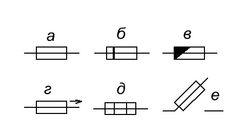
Resistors
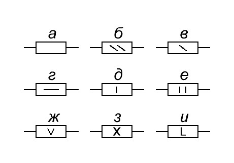
a) general designation
b) power dissipation 0.125 W
in) power dissipation 0.25 W
G) power dissipation 0.5 W
d) power dissipation 1 W
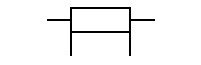
e) power dissipation 2 W
and) power dissipation 5 W
h) power dissipation 10 W
and) power dissipation 50 W
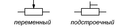
Resistors variable
Thermistors

Strain gauges

Varistor

Shunt
Capacitors

a) the general designation of the capacitor
b) varicond
in) polar capacitor
G) trimmer capacitor
d) variable capacitor
Acoustics

a) head phone
b) loudspeaker (speaker)
in) general designation of a microphone
G) electret microphone
Diodes

a) diode bridge
b) the general designation of the diode
in) zener diode
G) double-sided zener diode
d) bidirectional diode
e) Schottky diode
and) tunnel diode
h) reversed diode
and) varicap
to) Light-emitting diode
l) photodiode
m) emitting diode in an optocoupler
n) a radiation-receiving diode in an optocoupler
Meters of electrical quantities
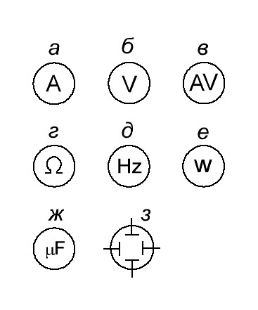
a) ammeter
b) voltmeter
in) voltammeter
G) ohmmeter
d) frequency meter
e) wattmeter
and) faradometer
h) oscilloscope
Inductors
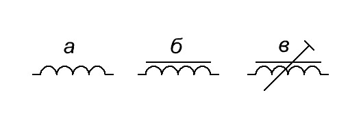
a) coreless inductor
b) core inductor
in) trimmer inductor
transformers

a) the general designation of the transformer
b) transformer with output from the winding
in) current transformer
G) transformer with two secondary windings(maybe more)
d) three-phase transformer
Switching devices
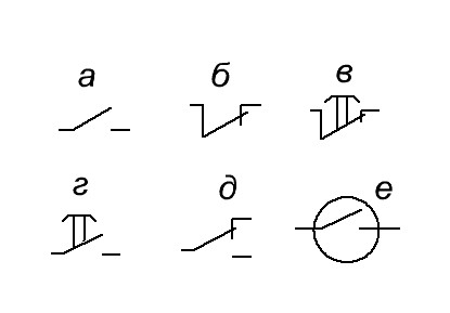
a) closing
b) opening
in) opening with return (button)
G) closing with return (button)
d) switching
e) reed switch
Electromagnetic relay with different groups of switching contacts (switching contacts can be separated in the circuit from the relay coil)

Circuit breakers
a) general designation
b) the side that remains energized when the fuse blows is highlighted
in) inertial
G) fast acting
d) thermal coil
e) switch-disconnector with fuse
Thyristors
bipolar transistor
unijunction transistor
![]()
FET with manager P-N transition
How to Learn to Read Schematic Diagrams
Those who have just started studying electronics are faced with the question: “How to read circuit diagrams? The ability to read circuit diagrams is necessary for self-assembly of an electronic device and not only. What is a principle diagram? A circuit diagram is a graphical representation of a collection of electronic components connected by current-carrying conductors. The development of any electronic device begins with the development of its circuit diagram.
It is on the circuit diagram that it is shown exactly how to connect the radio components in order to eventually get a finished electronic device that is capable of performing certain functions. To understand what is shown on the circuit diagram, you first need to know the symbol of those elements that make up electronic circuit. Any radio component has its own conventional graphic designation - UGO . As a rule, it displays a constructive device or purpose. So, for example, the conditional graphic designation of the speaker very accurately conveys the real device of the speaker. This is how the speaker is indicated on the diagram.
Agree, very similar. This is what the resistor symbol looks like.
An ordinary rectangle, inside which its power can be indicated (In this case, a 2 W resistor, as evidenced by two vertical lines). But in this way a conventional capacitor of a constant capacity is indicated.
These are fairly simple items. But semiconductor electronic components, such as transistors, microcircuits, triacs, have a much more sophisticated image. So, for example, any bipolar transistor has at least three terminals: base, collector, emitter. On the conditional image of a bipolar transistor, these conclusions are shown in a special way. To distinguish a resistor from a transistor in a circuit, firstly, you need to know the conditional image of this element and, preferably, its basic properties and characteristics. Since each radio component is unique, certain information can be graphically encrypted in a conditional image. So, for example, it is known that bipolar transistors may have a different structure: p-n-p or n-p-n. Therefore, the UGO of transistors of different structures are somewhat different. Take a look...
Therefore, before you begin to understand the circuit diagrams, it is advisable to get acquainted with the radio components and their properties. So it will be easier to figure out what is still shown in the diagram.
On our site, it has already been told about many radio components and their properties, as well as their symbol on the diagram. If you forgot - welcome to the "Start" section.
In addition to conditional images of radio components, other clarifying information is also indicated on the schematic diagram. If you look closely at the diagram, you will notice that next to each conditional image of the radio component there are several Latin letters, for example, VT , BA , C etc. This is the abbreviated letter designation of the radio component. This was done so that when describing the work or setting up the scheme, one could refer to one or another element. It is not difficult to notice that they are also numbered, for example, like this: VT1, C2, R33, etc.
It is clear that there can be an arbitrarily large number of radio components of the same type in the circuit. Therefore, in order to arrange all this, numbering is used. The numbering of parts of the same type, such as resistors, is carried out on circuit diagrams according to the “AND” rule. This is, of course, only an analogy, but quite descriptive. Take a look at any diagram, and you will see that the radio components of the same type are numbered on it starting from the upper left corner, then in order the numbering goes down, and then again the numbering starts from the top, and then down, and so on. Now remember how you write the letter "I". I think this is clear.
What else to tell about the concept? And here's what. On the diagram, next to each radio component, its main parameters or rating are indicated. Sometimes this information is placed in a table to make the circuit diagram easier to understand. For example, next to the image of a capacitor, as a rule, its nominal capacity in microfarads or picofarads. The rated operating voltage may also be indicated, if this is important.
Next to the UGO of the transistor, the type rating of the transistor is usually indicated, for example, KT3107, KT315, TIP120, etc. In general, for any semiconductor electronic components such as microcircuits, diodes, zener diodes, transistors, the rating of the component that is supposed to be used in the circuit is indicated.
For resistors, only its nominal resistance is usually indicated in kiloohms, ohms or megaohms. The rated power of the resistor is encrypted with slashes inside the rectangle. Also, the power of the resistor on the diagram and on its image may not be indicated. This means that the power of the resistor can be any, even the smallest, since the operating currents in the circuit are insignificant and even the smallest resistor produced by the industry can withstand them.
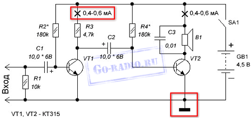
Here in front of you the simplest circuit two-stage audio frequency amplifier. The diagram shows several elements: a battery (or just a battery) GB1 ; fixed resistors R1 , R2 , R3 , R4 ; power switch SA1 , electrolytic capacitors C1 , C2 ; fixed capacitor C3 ; high impedance speaker BA1 ; bipolar transistors VT1 , VT2 structures n-p-n. As you can see, with the help of Latin letters, I refer to a specific element in the scheme.
What can we learn by looking at this diagram?
Any electronics works from electric current, therefore, the circuit must indicate the current source from which the circuit is powered. The source of current can be a battery and an AC power supply or a power supply.
So. Since the amplifier circuit is powered by a DC battery GB1, therefore, the battery has a polarity: plus "+" and minus "-". On the conditional image of the battery, we see that the polarity is indicated next to its terminals.
Polarity. It is worth mentioning separately. So, for example, electrolytic capacitors C1 and C2 have polarity. If we take a real electrolytic capacitor, then on its case it is indicated which of its conclusions is positive and which is negative. And now, the most important thing. When self-assembling electronic devices, it is necessary to observe the polarity of connecting electronic parts in the circuit. Failure to follow this simple rule will lead to the inoperability of the device and, possibly, other undesirable consequences. Therefore, do not be lazy from time to time to look at the circuit diagram by which you assemble the device.
The diagram shows that to assemble the amplifier, you will need fixed resistors R1 - R4 with a power of at least 0.125 watts. This can be seen from their convention.
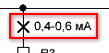
It can also be seen that the resistors R2* and R4* marked with an asterisk * . This means that the nominal resistance of these resistors must be selected in order to establish optimal operation of the transistor. Usually in such cases, instead of resistors, the value of which needs to be selected, a variable resistor with a resistance slightly larger than the value of the resistor indicated in the diagram is temporarily placed. To determine the optimal operation of the transistor in this case, a milliammeter is connected to the collector circuit break. The place on the diagram where you need to connect the ammeter is indicated on the diagram like this. The current is also indicated, which corresponds to the optimal operation of the transistor.
Recall that to measure the current, the ammeter is included in the open circuit.
Next, turn on the amplifier circuit with switch SA1 and begin to change the resistance with a variable resistor R2*. At the same time, the ammeter readings are monitored and the milliammeter shows a current of 0.4 - 0.6 milliamps (mA). On this, the setting of the transistor VT1 mode is considered complete. Instead of variable resistor R2 *, which we installed in the circuit for the time of adjustment, a resistor is placed with such a nominal resistance that is equal to the resistance of the variable resistor obtained as a result of adjustment.
What is the conclusion of all this long story about making the scheme work? And the conclusion is that if on the diagram you see any radio component with an asterisk (for example, R5*), this means that in the process of assembling the device according to this circuit diagram, it will be necessary to establish the operation of certain sections of the circuit. How to set up the operation of the device, as a rule, is mentioned in the description of the circuit diagram itself.
If you look at the amplifier circuit, you can also notice that there is such a symbol on it.
This designation indicates the so-called common wire. In the technical documentation, it is called the body. As you can see, the common wire in the shown amplifier circuit is the wire that is connected to the negative "-" terminal of the GB1 power battery. For other circuits, the common wire may also be the wire that is connected to the plus of the power source. In circuits with bipolar power, the common wire is indicated separately and is not connected to either the positive or negative output of the power source.
Why is "common wire" or "housing" indicated on the diagram?
With respect to the common wire, all measurements in the circuit are carried out, with the exception of those that are negotiated separately, and peripheral devices are also connected relative to it. Flows through a common wire total current Consumed by all circuit elements.
The common wire of the circuit is in reality often connected to the metal case of the electronic device or the metal chassis on which the printed circuit boards are mounted.
It should be understood that the common wire is not the same as the "ground". " Earth"- this is grounding, that is, an artificial connection to the ground through a grounding device. It is indicated on the diagrams as follows.
In some cases, the common wire of the device is connected to ground.
As already mentioned, all radio components in the circuit diagram are connected using current-carrying conductors. The current conductor can be copper wire or a copper foil track on printed circuit board. The current-carrying conductor in the circuit diagram is indicated by a regular line. Like this.
![]()
The places of soldering (electrical connection) of these conductors with each other, or with the conclusions of radio components, are depicted by a bold dot. Like this.
It should be understood that in the circuit diagram, only the connection of three or more conductors or conclusions is indicated by a dot. If the diagram shows the connection of two conductors, for example, the output of a radio component and a conductor, then the circuit would be overloaded with unnecessary images and at the same time its informativeness and conciseness would be lost. Therefore, it is worth understanding that in a real circuit there may be electrical connections that are not shown in the circuit diagram.
In the next part, we will talk about connections and connectors, repeating and mechanically connected elements, shielded parts and conductors. Click " Further"...
We advise you to read
, diagnosis, treatment Treatment of urogenital chlamydia") Urogenital chlamydia - description, causes, symptoms (signs), diagnosis, treatment Treatment of urogenital chlamydia
Urogenital chlamydia - description, causes, symptoms (signs), diagnosis, treatment Treatment of urogenital chlamydia The benefits and significance of hydroamino acid threonine for the human body L threonine what
 To wait or not to wait for a guy from the army For what reason can they be commissioned from the army
 Baked apples with cottage cheese Baked apples with cottage cheese

