Topic: Ramp generators andcurrent.
General information about sawtooth pulse generators (GPI).
Linear voltage generators.
Linearly changing current generators.
Literature:
Bramer Yu.A., Pashchuk I.N. impulse technology. - M.: Higher school, 1985. (220-237).
Bystrov Yu.A., Mironenko I.G. Electronic circuits and devices. - M.: Higher school, 1989. - S. 249-261,267-271.
General information about sawtooth pulse generators (GPI).
Tension sawtooth called such a voltage, which for some time changes according to a linear law (increases or decreases), and then returns to its original level.
Distinguish:
linearly increasing voltage;
linearly falling voltage.
Sawtooth pulse generator - a device that generates a sequence of sawtooth pulses.
Appointment of sawtooth pulse generators.
Designed to obtain voltage and current that varies in time according to a linear law.
Classification of sawtooth pulse generators:
By element base:
on transistors;
on lamps;
on integrated circuits (in particular, on op-amps);
By appointment:
sawtooth voltage generators (GPN) (another name - linearly varying voltage generators - CLAY);
sawtooth current generators (GPT) (another name - linearly varying current generators - GLIT);
By the method of switching on the switching element:
sequential circuit;
parallel circuit;
According to the method of increasing the linearity of the generated voltage:
with a current-stabilizing element;
compensation type.
Sawtooth pulse generator device:
The construction is based on an electronic key that switches the capacitor from charge to discharge.
The principle of operation of sawtooth pulse generators.
Thus, the principle of obtaining an increasing or falling voltage is explained by the process of charging and discharging a capacitor (integrating circuit). But, because the arrival of pulses on the integrating circuit must be switched, it is used transistor key.
The simplest schemes of sawtooth pulse generators and their functioning.
Schematically, the functioning of the GUI is as follows:
Parallel circuit:
When opening electronic key the capacitor is slowly charged through the resistance R to the value E, thus forming a sawtooth pulse. When the electronic key is closed, the capacitor quickly discharges through it.
The output pulse has the following form:
Serial scheme:


Thus, it can be seen (it can be noted as one of the main drawbacks) that the greater the amplitude of the voltage across the capacitor, the greater the nonlinearity of the pulse. Those. it is necessary to form an output pulse at the initial section of the exponential charge or discharge curve of the capacitor.
Sawtooth voltage generator for varicaps.
When working with a high-frequency generator tunable by a varicap, it was necessary to make a sawtooth voltage control generator for it. There are a great many circuits of "saw" generators, but none of those found fit, because. to control the varicap, an output voltage swing of 0 - 40V was required when powered by 5V. As a result of reflection, the following scheme turned out.
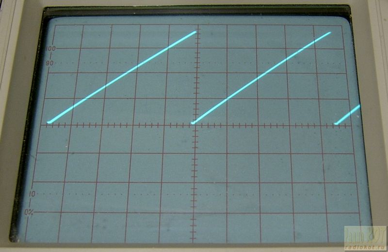
The sawtooth voltage is formed on the capacitor C1, the charging current of which is determined by the resistors R1-R2 and (to a much lesser extent) the parameters of the transistors of the current mirror VT1-VT2. A rather large internal resistance of the charging current source makes it possible to obtain a high linearity of the output voltage (photo below; vertical scale 10V / div). The main technical problem in such circuits is the discharge circuit of the capacitor C1. Usually, unijunction transistors, tunnel diodes, etc. are used for this purpose. In the above circuit, the discharge is produced by ... a microcontroller. This achieves ease of setting up the device and changing the logic of its operation, because. the selection of circuit elements is replaced by the adaptation of the microcontroller program.
The voltage across C1 is monitored by a comparator built into the microcontroller DD1. The inverting input of the comparator is connected to C1, and the non-inverting input to the reference voltage source on R6-VD1. When the voltage at C1 reaches the reference value (approximately 3.8V), the voltage at the output of the comparator jumps from 5V to 0. This moment is monitored by software and leads to reconfiguring the microcontroller's GP1 port from input to output and applying a logic 0 level to it. As a result, capacitor C1 turns out to be shorted to ground through the open transistor of the port and discharges quickly enough. At the end of the C1 discharge at the beginning of the next cycle, the GP1 output is again configured to the input and a short rectangular sync pulse is generated at the GP2 output with an amplitude of 5V. The duration of the discharge and synchronizing pulses is set by software and can vary over a wide range, because The microcontroller is clocked by an internal oscillator at a frequency of 4 MHz. When varying the resistance R1 + R2 within 1K - 1M, the frequency of the output pulses at the specified capacitance C1 changes from about 1 kHz to 1 Hz.
The sawtooth voltage at C1 is amplified by the op-amp DA1 up to the level of its supply voltage. The desired output voltage amplitude is set by resistor R5. The choice of the type of op-amp is due to the possibility of its operation from a 44V source. The voltage of 40V to power the op-amp is obtained from 5V using pulse converter on the DA2 chip enabled by standard scheme from her datasheet. The operating frequency of the converter is 1.3 MHz.
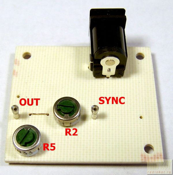
The generator is assembled on a board measuring 32x36 mm. All resistors and most capacitors are size 0603. The exceptions are C4 (0805), C3 (1206), and C5 (tantalum, frame A). Resistors R2, R5 and connector J1 are installed on the reverse side of the board. When assembling, you should first install the microcontroller DD1. Then, the wires from the programmer connector are temporarily soldered to the board conductors and the attached program is loaded. The program was debugged in the MPLAB environment, the ICD2 programmer was used for loading.
![]()
Although the described device has solved the problem and is still successfully operating as part of a sweep generator, to expand its capabilities, the above scheme can be considered rather as an idea. The upper frequency limit in this circuit is limited by the discharge time C1, which in turn is determined by internal resistance port output transistors. To speed up the discharge process, it is desirable to discharge C1 through a separate low resistance MOSFET. In this case, it is possible to significantly reduce the software delay time for the discharge, which is necessary to ensure the complete discharge of the capacitor and, accordingly, the drop in the output voltage of the saw to almost 0V (which was one of the requirements for the device). To thermally stabilize the operation of the generator, it is desirable to use an assembly of two PNP transistors in one package as VT1-VT2. At a low frequency of the generated pulses (less than 1 Hz), the final resistance of the current generator begins to affect, which leads to a deterioration in the linearity of the sawtooth voltage. The situation can be improved by installing resistors in the emitters VT1 and VT2.
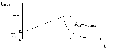
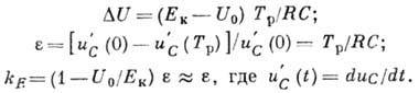
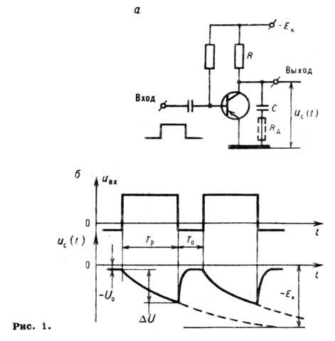
SAWTOOL VOLTAGE GENERATOR- a linearly changing generator (current), an electronic device that generates a periodic. voltage (current) sawtooth. Main The purpose of H. p. n. is to control the time sweep of the beam in devices using cathode ray tubes. G. p. n. also used in devices for comparing voltages, time delay and pulse expansion. To obtain a sawtooth voltage, the process (discharge) of a capacitor in a circuit with a large time constant is used. The simplest G. p. (Fig. 1, a) consists of integrating circuit RC and a transistor that performs the functions of a key controlled periodically. impulses. In the absence of pulses, the transistor is saturated (open) and has a low resistance of the collector-emitter section, capacitor FROM discharged (Fig. 1, b). When a switching pulse is applied, the transistor turns off and the capacitor is charged from a power source with a voltage of - E to- direct (working) course. Output voltage G. p. n. taken from the capacitor FROM, changes according to the law. At the end of the switching pulse, the transistor opens and the capacitor FROM quickly discharges (reverse) through a low resistance emitter - collector. Main characteristics G. p. n.: sawtooth voltage amplitude, coefficient. nonlinearity and coefficient. using the power supply voltage. When in this scheme
Forward run time T p and the frequency of the sawtooth voltage are determined by the duration and frequency of the switching pulses.
The disadvantage of the simplest G. p. is small k E at small. The required values of e lie in the range of 0.0140.1, with the smallest values related to the comparison and delay devices. The non-linearity of the sawtooth voltage during the forward stroke occurs due to the decrease in the charging current due to the decrease in the voltage difference . An approximate constancy of the charging current is achieved by including a non-linear current-stabilizing two-terminal device (containing a transistor or a vacuum tube) in the charge circuit. In such G. p. ![]() and
and ![]() . In G. p. with positive voltage feedback, the output sawtooth voltage is fed into the charging circuit as a compensating emf. In this case, the charging current is almost constant, which provides the values \u200b\u200b1 and \u003d 0.0140.02. G. p. n. used for scanning in cathode ray tubes with e-magn. beam deflection. To obtain a linear deviation, a linear change in current in the deflection coils is necessary. For a simplified equivalent coil circuit (Fig. 2, a), the current linearity condition is satisfied when a trapezoidal voltage is applied to the coil terminals. Such a trapezoidal stress (Fig. 2, b) can be obtained in G. p. when included in the charging circuit will add. resistance R e (shown in Fig. 1, a dotted line). The deflecting coils consume high currents, so the trapezoidal voltage generator is supplemented with a power amplifier.
. In G. p. with positive voltage feedback, the output sawtooth voltage is fed into the charging circuit as a compensating emf. In this case, the charging current is almost constant, which provides the values \u200b\u200b1 and \u003d 0.0140.02. G. p. n. used for scanning in cathode ray tubes with e-magn. beam deflection. To obtain a linear deviation, a linear change in current in the deflection coils is necessary. For a simplified equivalent coil circuit (Fig. 2, a), the current linearity condition is satisfied when a trapezoidal voltage is applied to the coil terminals. Such a trapezoidal stress (Fig. 2, b) can be obtained in G. p. when included in the charging circuit will add. resistance R e (shown in Fig. 1, a dotted line). The deflecting coils consume high currents, so the trapezoidal voltage generator is supplemented with a power amplifier.
The principle of operation of the relaxation generator is based on the fact that the capacitor is charged to a certain voltage through a resistor. Upon reaching desired voltage the control opens. The capacitor is discharged through another resistor to a voltage at which the control element closes. So the voltage on the capacitor increases exponentially, then decreases exponentially.
You can read more about how a capacitor charges and discharges through a resistor at the link.
Here is a selection of materials for you: The use of transistor analogs of a dinistor in relaxation generators is typical, since strictly defined parameters of the dinistor are necessary for the calculation and accurate operation of this generator. Some of these parameters for industrial dinistors either have a large technological spread, or are not standardized at all. And to make an analogue with strictly specified parameters is not difficult. Sawtooth voltage generator circuitThe relaxation generator looks like this: (A1)- relaxation generator on a diode thyristor (dinistor), (A2)- in circuit A1, the dinistor is replaced by a transistor analog. It is possible to calculate the parameters of a transistor analogue depending on the transistors used and the resistor values. Resistor R5 is chosen small (20 - 30 Ohm). It is designed to limit the current through the dinistor or transistors at the moment they are opened. In calculations, we will neglect the influence of this resistor and assume that there is practically no voltage drop across it, and the capacitor discharges instantly through it. The dinistor parameters used in the calculations are described in the article current-voltage characteristic of a dinistor. [Minimum output voltage, V] = [Maximum output voltage, V] = Calculation of the resistance of the resistor R4For resistor R4, two relationships must be satisfied: [Resistance R4, kOhm] > 1.1 * ([Supply voltage, V] - [Closing voltage of the dinistor, V]) / [Holding current, mA] This is necessary so that the dinistor or its analogue is securely locked when the capacitor is discharged. [Resistance R4, kOhm] Supply voltage, V] - [ Dinistor unlocking voltage, V]) / (1.1 * [Release current, mA]) This is necessary so that the capacitor can be charged to the voltage required to unlock the dinistor or its equivalent. Coefficient 1.1 was chosen conditionally from the desire to get a 10% margin. If these two conditions conflict with each other, then this means that the supply voltage of the circuit for this thyristor is chosen too low. Relaxation oscillator frequency calculationApproximately estimate the frequency of the generator can be from the following considerations. The oscillation period is equal to the sum of the capacitor charge time to the dinistor trigger voltage and the discharge time. We agreed to consider that the capacitor is discharged instantly. Thus, we need to estimate the charge time. Second option: R1- 1 kOhm, R2, R3- 200 Ohm, R4- trimmer 3 kOhm (set to 2.5 kOhm), Supply voltage- 12 V. transistors- KT502, KT503. Generator Load RequirementsThese relaxation generators can operate with a load that has a high input resistance so that the output current does not affect the process of charging and discharging the capacitor. [Load resistance, kOhm] >> [Resistor R4, kOhm] |
 Sawtooth voltage generators (SPG) are widely used in electronic circuits. sawtooth voltage is called, which increases relatively slowly according to a linear law and then quickly decreases to its original value. Sawtooth voltage is obtained by fig. 32.1
 when the capacitor is charged. The simplest circuit sawtooth voltage generator is shown in fig. 32.1, a.
In the initial state, when there is no input signal, the transistor V T is in the open state due to the positive potential supplied to the base of the transistor through the resistor Rb. The voltage across capacitor C is equal to the voltage between the collector and emitter of an open transistor. With the input of the generator of a rectangular voltage pulse of negative polarity, the transistor closes and the capacitor C begins to charge from the collector power source through the resistor Rk. After the input pulse stops, the transistor V T opens and a relatively fast discharge of the capacitor C occurs through the open transistor. The duration of the sawtooth pulse is equal to the duration of the input rectangular pulse (Fig. 32.6), and the duration of the reverse stroke is the time the capacitor is discharged through the transistor. Since the resistance of the resistor Rk is significantly more resistance open transistor, then the pulse duration is much longer than the duration of the reverse stroke. Thus, the output voltage taken from the capacitor has a sawtooth shape
GPN are used to obtain an electron beam sweep in cathode ray tubes of oscilloscope, television and radar devices.
33. General information about electronic oscilloscopes.
Electronic oscilloscope called a device designed for visual observation, recording and measuring the parameters of electrical signals.
The wide distribution of electronic oscilloscopes is due to their versatility, clarity of the image of the process under study, and good measuring parameters.
In order to understand the operation of an electronic oscilloscope, it is necessary first of all to study the operation of its main unit - a cathode ray tube.
electron beam tubes are electrovacuum devices that use an electron stream concentrated in the form of a beam or a beam of rays.
Most cathode ray tubes belong to the group of electronic graphic electrovacuum devices designed to obtain a visible image on the screen that glows under the action of
--1500V brightness focus
Rice. 33.1
incident electron flow, or to register the resulting image on the photosensitive layer. These include oscilloscope tubes.
The device and switching circuit of an oscillographic cathode ray tube (CRT) with electrostatic focusing and deflection of the electron beam are shown in fig. 33.1.
The cathode ray tube consists of the following main parts:
1) a glass container in which a vacuum is created:
2) an electron searchlight that creates a narrow electron beam directed along the axis of the tube;
3) a deflecting system that changes the direction of the electron beam;
4) a screen glowing under the action of an electron beam.
Consider the purpose and arrangement of individual elements of the tube.
A deep vacuum is created in the balloon, which is necessary for the unhindered passage of electrons. The electronic searchlight of the tube consists of a cathode, a control electrode and two anodes and is located in a narrow elongated part of the cylinder. Cathode To It is made in the form of a small nickel cylinder, on the end part of which an oxide layer is applied, which emits electrons when heated. The cathode is enclosed in a control electrode (modulator) M also cylindrical. At the end of the control electrode there is a small hole (diaphragm) through which the electron beam passes. Several tens of volts of negative voltage relative to the cathode are applied to the control electrode, with the help of which the brightness of the glow of the spot on the tube screen is regulated. Control electrode acts like a control grid electronic lamp. At a certain value of this voltage, the tube is blocked, and the luminous spot disappears. The specified adjustment is placed on the front panel of the oscilloscope and is labeled "Brightness".
Preliminary focusing of the electron beam is performed in the space between the modulator and the first anode. The electric field between these electrodes presses the electrons to the axis of the tube and they converge to a point O at some distance from the control electrode (Fig. 33.2). Further focusing of the beam is performed by a system of two anodes A 1 and A 2
The first and second anodes are made in the form of open metal cylinders of various lengths and diameters, inside which diaphragms with small holes are located at some distance from each other.
A positive accelerating voltage is applied to the anodes (at the first
300-1000 V, for the second 1000-5000 V and more). Since the potential of the second anode A 2 above the potential of the first anode A 1 , then electric field between them will be directed from the second anode to the first. Electrons that have fallen into such an electric field will be deflected by it in the direction towards the axis of the tube and receive acceleration in the direction of movement towards the screen . Thus, the action of the anode system is equivalent to the action optical system converging and divergent lenses. Therefore, the focusing anode system of a cathode ray tube is sometimes called electronic static lens. Accurate focusing of the beam is performed by changing the voltage at the first anode. This adjustment is placed on the front panel of the oscilloscope and labeled "Focus".
The formed electron beam after the second anode enters the space between two pairs of mutually perpendicular deflecting plates X 1 X 2 and Y 1 Y 2, called electrostatic deflection system. First pair of plates X 1 X 2, placed vertically causes the beam to deviate in the horizontal direction. Plates of the second pair Y 1 Y 2, placed horizontally cause the beam to deviate in the vertical direction. When a pair of plates is supplied constant pressure, then the electron beam is deflected towards the plate, which is under a positive potential, which leads to a corresponding movement of the luminous spot on the screen.
When an alternating voltage is applied to the plates, the movement of the luminous spot across the screen forms luminous lines.
Screen E A cathode ray tube is a glass surface coated on the inside with a thin layer of a special substance (phosphor) that can glow when bombarded with electrons.
To obtain an image on the screen of the tube, the investigated signal voltage is applied to the vertical deflection plates Y 1 Y 2, a pa plate X 1 X 2- sawtooth voltage called sweep voltage (Fig. 33.3).
Location on AB the sweep voltage is linearly dependent on time, and under the action of this voltage, the light spot moves along the tube screen along the horizontal axis in proportion to time. Location on Sun the sweep voltage drops sharply, and the light spot returns to its original position.
If simultaneously with the sweep voltage to the plates Y 1 Y 2 bring the investigated sinusoidal voltage, then on the screen of the tube you will get one period of the sinusoid (Fig. 33.4).
 The positions 0, 1, 2, ... of the light spot on the screen of the tube at the corresponding moments of time are determined by the instantaneous values of the investigated and developing voltages.
If the sweep period Tr is selected as a multiple of the period of the voltage under study, then the oscillograms obtained in subsequent periods are superimposed on each other and a stable and clear image of the process under study is observed on the screen
We advise you to read
, diagnosis, treatment Treatment of urogenital chlamydia") Chlamydia urogenital - description, causes, symptoms (signs), diagnosis, treatment Treatment of urogenital chlamydia
Chlamydia urogenital - description, causes, symptoms (signs), diagnosis, treatment Treatment of urogenital chlamydia The benefits and significance of hydroamino acid threonine for the human body L threonine what
 To wait or not to wait for a guy from the army For what reason can they be commissioned from the army
 Baked apples with cottage cheese Baked apples with cottage cheese

