Hey Geektimes!
Managing powerful loads is a fairly popular topic among people who are somehow related to home automation, and, in general, regardless of the platform: be it Arduino, Rapsberry Pi, Unwired One or another platform, turn on or turn off some kind of heater, boiler or duct fan sooner or later have to.
Capacitive nature of the load
Things get more complicated as you watch as the tension changes. Between the motor being on and at rest, the voltage will carry current, but because the motor requires additional current to establish the state of the state, it will draw more current than the motor's rated power. This current is called the inrush current or inrush current. This additional current will be needed for a few milliseconds while the motor goes into steady state.
The traditional dilemma here is what, in fact, to commute. As many have seen from their sad experience, Chinese relays do not have the proper reliability - when switching a powerful inductive load, the contacts spark strongly, and at one fine moment they can simply stick. We have to put two relays - the second for safety net to open.
Since the cables that connect the source to the motor and the wires that make the windings inside the motor have their own resistance, capacitance and inductance, it is important to consider the effect they have on the entire system. Resistance has the same effect during start or steady state, but induction and capacitance only affect the dynamic state, so your starting current will overcome these factors during the start of your motor.
When a dynamic voltage is applied to the load, the current does not equalize with the voltage. This means that either the current drives the voltage, or it lags the voltage. The easiest way to see this is with a vector diagram. Resistance is from the origin to the right, induction is from the source up, and capacitance is from the origin down.
Instead of a relay, you can put a triac or a solid-state relay (in fact, the same thyristor or field device with a logic signal control circuit and an optocoupler in one case), but they have another minus - they heat up. Accordingly, a radiator is needed, which increases the dimensions of the structure.
I want to talk about a simple and rather obvious, but at the same time rare scheme that can do this:
All 3 affect the power required from the source to make the motor spin and the voltage dynamic. This is where the power factor comes in. The work done by the motor is equivalent to the motor's rated power, but only the power dissipated within the motor's resistance works. Any power dissipated in the capacitance or inductance of the motor or cables is lost.
Do not try to understand that your source also sees the total power consumption, i.e. real and apparent combined, which means by reducing the apparent power of each load, you can add more loads to the same source. In fact, we aim to reduce the power factor to 95-98 for several reasons.
- Galvanic isolation of input and load
- Switching inductive loads without current and voltage surges
- No significant heat generation even at maximum power
But first, a few illustrations. In all cases, TTI TRJ and TRIL series relays were used, and a 650 W vacuum cleaner was used as a load.
Power factor less than 95 is usually penalized by supplier utilities which gets a power factor better than 98 is really expensive and not worth the investment in a single power factor, causes other supply harmonic pollution problems. A "worse" power factor than 95 just wastes energy and money. . Since your electricity bill is reduced by installing power factor correction equipment, the equipment will pay for itself in about 3 years, so you are almost always using them.
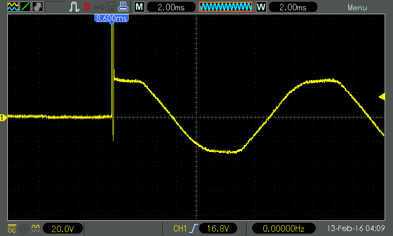
The classic scheme - we connect the vacuum cleaner through a conventional relay. Then we connect an oscilloscope to the vacuum cleaner (Caution! Either an oscilloscope or a vacuum cleaner - or better both - must be galvanically isolated from the ground! Don’t climb into the salt shaker with your fingers and eggs! You don’t joke with 220 V!) And look.
Include:

If you need Additional Information let me know as this is a complex topic to untie your head and use intermediate knowledge. This uses magnetic energy to produce work. Most electrical appliances, motors, and other devices can be classified as either inductive or restorative, and this is usually related to how they absorb and process energy. Inductive circuits tend to be large and usually rely on a coil or other routing system for energy storage and delivery, and as a result most are found in industrial and heavy duty applications.
I had to almost reach the maximum mains voltage (trying to tie an electromagnetic relay to a zero crossing is a disastrous task: it is too slow). A short ejection with almost vertical fronts boomed in both directions, interference flew in all directions. expected.
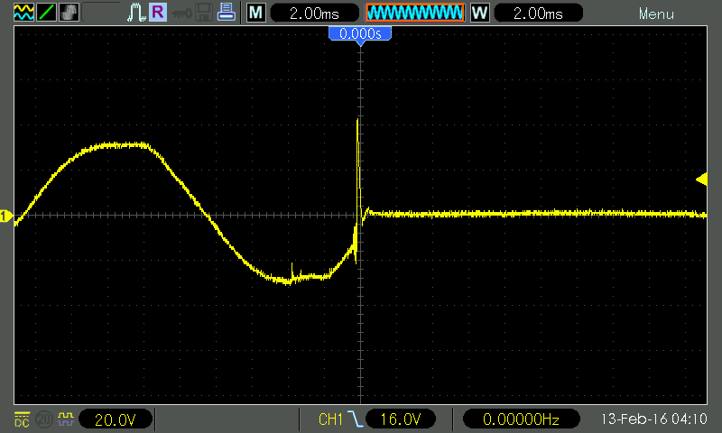
Turn off:

Common examples include transformers, electric motors, and electromechanical relays. These kinds of tools basically store energy until it's needed, and when it's available, they convert it with a series of magnetic fields; together this process is known as "induction". These kinds of loads often need to be used and protected to keep power flowing in only one direction, as the force of the power can damage the circuit or otherwise connected circuit breakers.
Electricity is measured in separate units based on output needs, but in most cases, the total amount of energy passing through a circuit is referred to as "load" at the point where the device absorbs or actually uses power. Loads can be large or small and have different strengths in different applications.
A sharp loss of voltage on an inductive load does not bode well - the surge flew up. In addition, do you see these noises on the sinusoid milliseconds before the actual shutdown? This is the sparking of the relay contacts that have begun to open, because of which they will boil one day.
So, it is bad to switch an inductive load with a “naked” relay. What will we do? Let's try to add a snubber - an RC circuit of a 120 ohm resistor and a 0.15 uF capacitor.
In most cases, there are two types of loads, and inductive models are usually characterized by the use of electromagnetic fields. Electromagnetism in these settings will actually force the energy to move from a source, such as an output or voltage adapter, to the heart of the circuit, where it can be used to power, no matter what the device is.
When a differential voltage signal is applied to the wires of an inductor, the inductor converts electricity into an electromagnetic field. When the voltage differential is removed from the wires, the inductor will attempt to maintain the amount electric current flowing through it. It discharges when the electromagnetic field is destroyed, or if an electrical path is created between two inductor conductors.
Include:
Better, but not much. The ejection slowed down in height, but was generally preserved.
Turn off:
The same picture. The debris remained, moreover, the sparking of the relay contacts remained, albeit greatly reduced.
An example is an electric motor. In these cases, the load is used to convert electricity into physical work. It usually takes more energy to start the rotor spinning at the beginning than it takes to keep the already spinning rotor in motion, and when voltage is applied to the motor terminals, the motor generates a change. This change causes electromotive force, which opposes the force of the forward, which starts the rotation of the engine; this phenomenon is called reverse electromotive force.
This means that such loads will require a power supply that can provide enough electrical power to start the motor. This power supply must also provide enough power to run the motor when needed. The inductive process is usually prone to what is known as "blowdowns", which means that the energy is not tested and can overload the circuit if it is not limited. Also, some inductive loads, such as those in an electromechanical relay, can send a pulse of power back into the circuit when power is removed from the load, which can damage the circuit.
Conclusion: with a snubber it is better than without a snubber, but globally it does not solve problems. However, if you want to switch inductive loads with a conventional relay, install a snubber. Ratings must be selected for a specific load, but a 1-Watt 100-120 ohm resistor and a 0.1 uF capacitor seem like a reasonable option for this case.
Related reading: Agilent - Application Note 1399, "Maximizing the Life Span of Your Relays". When the relay operates on the worst type of load - the motor, which, in addition to inductance, also has very low resistance at startup - good authors recommend reducing the relay's passport life five times.
For this reason, most devices and machines made in this style also have protective "diodes" that basically act as circuit breakers and require that the energy be able to enter - but forbid it to also flow back out. When the power is off, the power surge dissipates, providing a one-way electrical path through the inductor. It will dissipate electricity until the electromagnetic field collapses or until the surge current is sufficient to activate the diode.
An electrical load is an electrical component that is part of electrical circuit, which consumes electrical energy and hides it in another form of energy. Typically, an electrical load is connected to the output terminals of a voltage source, as this is the device to which power is applied.
And now let's make a knight's move - we will combine a triac, a triac driver with zero detection and a relay into one circuit.

What is on this diagram? On the left is the entrance. When a "1" is applied to it, the capacitor C2 charges almost instantly through R1 and the lower half of D1; opto-relay VO1 turns on, waits for the next zero crossing (MOC3063 - with built-in zero detector circuit) and turns on triac D4. The load is started.
Electrical loads can be classified into different categories according to numerous factors such as; load, load, load consumer category, load importance, number of phases of the electrical load and according to the unit of electrical loads.
The most common classification of an electrical load depends on its load. Namely, resistive load, inductive load, capacitive load and combined loads. Resistive load limits flow electrical energy in a circuit and converts it into thermal and light energy. For example, a lamp and a heater are both resistive loads.
Capacitor C1 is charged through a chain of R1 and R2, which takes approximately t=RC ~ 100ms. These are several periods of mains voltage, that is, during this time the triac will have time to turn on for sure. Then Q1 opens - and relay K1 turns on (as well as LED D2, shining with a pleasant emerald light). The relay contacts shunt the triac, so further - until it is turned off - it does not take part in the work. And it doesn't get hot.
This type of load consumes electricity in such a way that the voltage and current waves remain "in phase" with each other. Therefore, the power factor for a resistive load is unity. Resistive load resistance is measured in ohms and power is measured in watts.
An inductive load resists current changes and uses magnetic fields for work. An inductive load has a coil that stores magnetic energy when a current passes through it. For example, transformers, generators and motors are inductive loads.
Shutdown - in reverse order. As soon as "0" appears at the input, C1 quickly discharges through the upper arm of D1 and R1, the relay turns off. But the triac remains on for about 100 ms, as C2 is discharged through the 100-kilohm R3. Moreover, since the triac is held open by current, even after VO1 is turned off, it will remain open until the load current drops in the next half cycle below the triac holding current.
This type of load causes a current wave to be "out of phase" with the voltage wave, causing the current wave to "lag" the voltage wave. Therefore, the power factor for an inductive load lags behind. A capacitive load is in some sense the opposite of an inductive load. A capacitive load resists voltage changes and stores electricity. For example, capacitor banks and motor starters are capacitive loads.
This type of load causes the current wave to be "out of phase" with the voltage wave, causing the current wave to "lead" the voltage wave. Therefore, the power factor for a capacitive load is the leading one. Most electrical loads are not purely resistive, inductive, or capacitive. Many practical loads use various combinations of resistors, inductors, and capacitors to achieve a particular function. For example, motors often use capacitors to assist in starting and running.
Inclusion:
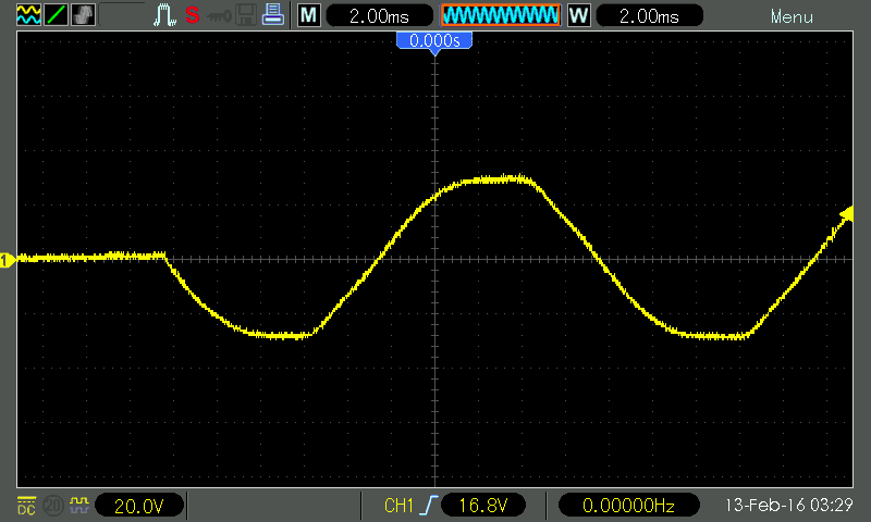
Shutdown:

Beautiful, isn't it? Moreover, when using modern triacs that are resistant to rapid changes in current and voltage (all major manufacturers have such models - NXP, ST, Onsemi, etc., the names begin with “BTA”), the snubber is not needed at all, in any form.
The power factor of such a load is less than unity and is either lagging or leading. The use of universal relays for inductive loads should not sacrifice their size, cost, or functional advantages. One of the most frustrating problems for control engineers and technicians is the potential early failure of interposing or interposing relays used for inductive loads. This is especially true of the universal "ice cube" and the increasingly popular compact compact relay, even when the relays appear to be large enough to power low-resistance loads such as small motors, solenoids direct current and contactor coils.
Moreover, if we remember smart people from Agilent and see how the current consumed by the motor changes, you get this picture:
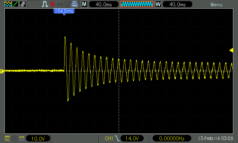
The starting current exceeds the operating current by more than four times. For the first five periods - the time by which the triac leads the relay in our circuit - the current drops by about half, which also significantly softens the requirements for the relay and prolongs its life.
Why does a 6A DC relay fail prematurely when driving a DC solenoid with a current draw of 1A or less? How can these problems be avoided? Is it really necessary to sacrifice the size, cost and functional benefits of the relay general purpose when moving inductive loads? If you find yourself asking these kinds of questions or dealing with the frustration that usually follows, you are among those who have battled those ever-present "inductive load demons".
Yes, the circuit is more complicated and more expensive than a conventional relay or a conventional triac. But often it's worth it.
The installation of a passive smoothing filter at the output of the rectifier significantly affects the physical processes in the rectifier itself. The inductive nature takes place when the rectifier operates on a filter, starting with an inductance or on the winding of a relay, contactor, excitation winding electrical machines and others. A diagram of the simplest rectifier with an inductive load is shown in Fig. 3.34. In these schemes, as a rule, the condition >> i.e. inductive reactance throttle at ripple frequency more resistance loads. It is known that the current in the inductance lags behind the voltage by π/2 and the process of current rise and fall ends within one period.
Figure 3.34 - Single-phase, single-ended rectifier with
inductive nature of the load
The current in the circuit (i 2) is non-sinusoidal, since in addition to the EMF of the secondary winding, the EMF of the induction of the throttle acts in it.
With an increase in current, energy is accumulated in the magnetic field of the inductor, and with a decrease in current, this energy is released.
Thus, the result of turning on the inductance is to “pull” the gate current. The current flow angle depends on the time constant, where R \u003d R H + r D + r 2, r D is the resistance of the diode, r 2 is the ohmic resistance of the secondary winding of the transformer (Fig. 3.35).
Figure 3.35 - Dependence of the angle of current flow on the time constant
It is difficult to fulfill the ratio. losses in the inductor itself increase and the overall efficiency decreases significantly. Therefore, with an inductive nature of the load, multi-phase circuits p ≥ 2 are used, where current continuity is easily ensured during the ripple period.
Let's take a three-phase single-cycle rectifier (Fig. 3.36). In this figure, L S is the leakage inductance of the secondary winding; r is the loss resistance (r = r 2 + r 1 / n 2), which is usually r<< Rн; – угол перекрытия фаз. Поскольку >> the current in the load is constant, and the current through the valve has the form of a rectangular pulse. The transfer of current from valve to valve due to leakage inductance cannot occur instantly. Its EMF of self-induction prevents a change in current - in one phase it decreases, and in the other it increases. As a result, the current flows simultaneously in two phases. This phenomenon is called the overlapping of the phase currents. It significantly affects the qualitative and quantitative ratios in the rectification scheme.
Figure 3.36 - Three-phase single-ended rectifier
In single cycle single-phase circuit there is no current transfer from one valve to another, so Ls in it practically does not affect physical processes. AT three-phase circuit there is a finite transition time of the current (phase switching). If we neglect the resistance of the valves and the transformer, then there will be no current pulling - the switching is instantaneous. Due to phase overlap, the constant component U 0 is reduced by the area of the triangle in the voltage U d .
As a result, the presence of r and Ls leads to a sharper drop in the external characteristic of the rectifier (i.e., an increase in Rout), which is shown in Fig. 3.37.
Figure 3.37 - External characteristic of the rectifier with inductive
the nature of the load
Here, when the load current is less than a certain value I 0cr, the relation ceases to be fulfilled. The inductor current becomes intermittent, it discharges completely and the voltage increases.
For rectifiers with an inductive nature of the load, the following conclusions can be drawn:
1) The inductive component of the resistance and load must be commensurate with Rn (otherwise the efficiency will be low).
2) The shape of the current curve of the valve approaches a rectangular shape.
3) The duration of each phase does not depend on the inductance in the load circuit, but is determined by the number of phases of the rectification (pulse) and the leakage inductance of the transformer.
4) The presence of leakage inductance leads to the overlap of the phase currents, while U 0 decreases, and the ripple at the input of the smoothing filter increases.
Capacitive nature of the load
The capacitive nature of the load occurs when the rectifier operates on a filter, starting with a capacitance, as shown in Fig. 3.38.
The constant of the charge circuit is much less than the constant of the discharge circuit, therefore the charge time (angle) is much less than the time of discharging the filter capacitor to the load. There is a cut-off of the valve current. With an increase in R H, the discharge slows down and the intersection point of U 2 and U C shifts, the angle decreases, and the voltage ripple also decreases. At current
Figure 3.38 - The simplest rectifier with a capacitive load
load equal to zero, the capacitor is not discharged and U 0 \u003d U m 2. The reverse voltage across the valve is also maximum and equal to . The external characteristic is non-linear and the output impedance can only be determined at the operating point in increments (Figure 3.39).
Figure 3.39 - External characteristic of the rectifier with capacitive
load
The single-phase, single-ended rectification circuit has rather high ripple at a low fundamental frequency and makes poor use of the transformer. However, the simplicity of single-cycle circuits makes them more attractive than push-pull circuits for obtaining high voltages.
Consider a voltage doubling circuit. It is shown in fig. 3.40 and consists of two single-cycle rectifiers, each of which uses its own
Figure 3.40 - Voltage doubling circuit (symmetrical)
half wave of mains voltage. The voltage on the load is the sum of the voltages on the capacitors C 1 and C 2. If the ripples are small, then the constant component on the load
When adding, all odd harmonics are compensated, including the first (p = 2). The disadvantage of the circuit is the lack of a common point between the transformer and the load, which is inconvenient from the point of view of electrical safety.
Another doubling scheme is shown in Figure 3.41. It is called asymmetrical and has common point networks and loads.
Figure 3.41 - Unbalanced voltage doubling circuit
In this circuit, the frequency of the first harmonic of the ripples is equal to the mains frequency. Capacitor C 1 performs the function of an intermediate energy storage device, therefore the mass and volume of an asymmetric doubler is greater than that of a symmetrical one.
But we got a regular structure that can be increased, as shown in Fig. 3.42.
Figure 3.42 - Asymmetric voltage doubling circuit (a) and
voltage multiplier by six (b)
In the voltage multiplier, the load can also be connected to the upper group of capacitors - we get a multiplier by five. Multipliers are produced in the form of a non-separable block. The number of capacitors is equal to the multiplication factor. Output impedance is measured in kilo-ohms.
Controlled Rectifiers
A controlled rectifier is a rectifier whose output voltage can be regulated at a constant input voltage.
You can control the output voltage by switching the turns of the primary or secondary windings transformer, laboratory autotransformer (LATR) or the introduction of a rheostat into the current circuit. The first method gives the discreteness of adjustment, which is not always acceptable, the second, due to the presence of sliding contacts, has low reliability, and the third (using rheostats) has low efficiency. Therefore, controlled valves are used, which are included instead of uncontrolled ones in the rectification circuit.
Thyristors are used as such valves - four-layer p-n-p-n structures. Figure 3.43a,b,c shows the symbol, equivalent circuit and CVC of the thyristor (triac), respectively. :
Figure 3.43 - Symbol, equivalent circuit and CVC of the thyristor
In the normal state, the thyristor is locked. There are two stable states in the circuit: open (point A) and closed (point B).
Increasing the source voltage from 0 to E at Iue = 0 leads to the movement of the operating point along the lower section of the characteristic. If you apply a control current pulse Iue sufficient to turn on, then rt. will go to point A and the control circuit will cease to influence the processes in the anode circuit of the thyristor - the control circuit is not needed. This is a system with internal positive feedback, so thyristors have a large power gain.
Usually, E is always less than the turn-on voltage "along the anode" (U amax) by 20 ... 30%. You can turn off the thyristor only by reducing Ia to a level less than the holding current (Iud), by increasing Rn or reducing E.
In the open state, thyristors pass large currents (hundreds of amperes), but they are inertial, the turn-on time is 0.1 ... 10 μs, and the turn-off time is 1 ... 100 μs.
Along with the considered thyristor, there is a group of four-layer devices with various properties, these are dinistors, triacs and lockable thyristors. They are shown in fig. 3.44.
Figure 3.44 - Symbol dinistor (a), triac (b)
and a lockable thyristor (c).
The dinistor has a regulated turn-on voltage across the anode. This is a two-electrode device. The triac is designed to work in circuits alternating current in this case, the control signal can be applied relative to the cathode or relative to the anode. All the devices mentioned above are turned off only by reducing its anode current below the holding current.
However, there are also so-called lockable thyristors, i.e. by applying current to the RE circuit in the opposite direction, the thyristor can be turned off. But at the same time, the turn-off gain is an order of magnitude lower than the turn-on gain.
All of these devices are widely used in automation devices and power supplies as regulators, stabilizers and protection devices.
Usually a thyristor is placed in the rectification circuit instead of an uncontrolled valve. Let's take a single-phase bridge (Fig. 3.45). In this figure - the thyristor switching angle (the angle relative to the natural switching point of the uncontrolled valve).
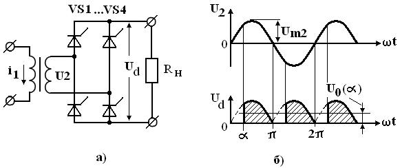
Figure 3.45 - Single-phase controlled bridge
Find the constant component of the voltage across the load.
Considering that the voltage U 2 is harmonic, then
(3.44) If in (3.44) we accept , then is the voltage at the output of the uncontrolled rectifier; if , then . Dependence is the regulating characteristic of the controlled rectifier. It is shown in Figure 3.46 and is non-linear.

Figure 3.49 - Unbalanced controlled rectifier
Here, the diodes play the role of a zero gate, therefore; asymmetry can be any (uncontrolled valves can be in the anode or cathode group or as in Fig. 3.49).
Thyristors are also used in booster circuits, which, compared to those considered, have a higher efficiency, since they convert only part of the energy for the load. The rectifier circuit with a voltage boost is shown in Fig. 3.50. Here is the minimum output voltage
Figure 3.50 - Rectifier with voltage boost
provided by uncontrolled rectifier VD1 and VD2. The voltage increase is achieved by turning on the thyristors VS1 and VS2. In the maximum mode, the diodes are always closed and the switching angle is . Such circuits have good energy performance, but additional windings are required on the transformer.


