Today, when new technologies and electrical appliances appear almost every year, it is very difficult to do without some equipment at home. A particularly important role in our lives is given to power supplies. Any radio amateur should be able to assemble this device with his own hands.
In today's article, we will talk about how to make such an important electrical appliance in the home laboratory as the lm317 power supply. The scope of such equipment is huge, so the knowledge of how to assemble it with your own hands will be relevant and useful in everyday life.
A suitable transformer for a linear laboratory source will have at least 2 kg. If you dismantle a new device, you will find small transformers up to 200 g and a few centimeters in size. Such transformers are used in switched sources and are completely inappropriate for linear sources.
The photographs show examples of suitable transformers. In two cases, these are old pieces. The third part is suitable for feeding tubes, so, for the sake of interest, the source is not suitable. If you cannot get the old transformer, you will have to look for a new one. In this case, it is useful to look at the offer of toroidal transformers, which are somewhat more expensive, but on the other hand are smaller and lighter.
Device Features
The power supply is an important attribute of any amateur radio home workshop. The principle of operation of the power supply is that it can convert the voltage and current in the network to the parameter we need for powering and connecting various electrical appliances. At the same time, such a device provides high protection against short circuit.
The power supply can be of two different types:
An idea that doesn't come out of my head: connect the power supply and the lamp primary transformer to the series. If the transformer is faulty, the lamp lights up, but there is no short circuit. The main function of a power supply is to provide the device with sufficient power and stable, smoothed voltages. However, there is still room for further design experiments.
More suitable is more galvanically isolated outputs. You can also turn on electrical appliances that require more power - most often projects with operational amplifiers, audio amplifiers, etc. Several links to interesting projects.
- adjustable;
- impulse.
In addition, the scheme that is used to assemble this type of power supply can be different - from the simplest to the most complex.
Note! If you are new to radio electronics, then first you should choose simple circuits. Such a scheme will be clear to you and will allow you to quickly create a device for a wide variety of needs.
And almost every issue of Practical Electronics. . Not only me, but others are interested in creating and inspiring experiences. Most power supply articles start with "The power supply is one of the most important things in a hobby shop" or something like that. Sometimes the sentences change a little, someone is using a power source, someone is in a laboratory, someone is a workshop, someone is just a source, but the meaning is always the same.
Sura Soviet car and several batteries were at home. But it was curtain time and things were different. The meteors remained at a distance, while Sura and my batteries remained at home. Shifts and various other activities came into play, so resource building continued to move forward and further into the future. What's more, I managed to make some spare parts in stock, so the price didn't go up that high. And if not for my impudence and broken parts, she remained. Relatively simple design - small coolers, low heat - short circuit resistance - very good voltage stability - current regulation.
Approximate scheme
The decision to assemble a power supply on an lm317 chip greatly simplifies the assembly process. At the same time, the circuit itself is also simplified. Thanks to the microcircuit, it becomes possible to make a regulated power supply and provide power stabilization.
If you believe the comments left by radio amateurs, such an assembly is several times superior to domestic counterparts, while possessing large resources.
Even a little more demanding design, this is a converter - the output interferes with the inverter, but only a little - the current regulation is a fuse, it is not a full current source, it gradually regulates the current. - the voltage control controls the regulator with three torques, so the output drops slightly with load - if the control voltage potentiometer fails, the full voltage from the rectifier will be output.
Thus, these will be the pros and cons of the sources. It doesn't look like it, but it clearly outweighs it. As already mentioned, the current regulation is a fuse, it is gradually used and serves to protect the connected equipment. As for the voltage drop under load, so it compares the specified reference voltage regulator with the voltage at its output, but since they lead more conductors to the output terminals and, especially in the return flow, additional resistors are connected that produce a voltage drop that the regulator cannot accept into account, they are not aware of them, so the tension decreases somewhat with load.
Principle of operation
Now let's consider the principle of operation of the device, since when assembling a lm317 type power supply in order to be able to regulate the voltage indicator, as well as the current strength in the network, it is necessary to clearly know and understand this aspect. Without this, it is impossible to properly assemble the device, even if the circuit is quite simple.
A voltmeter measures terminals, unlike a stabilizer. If this resource property is bad, you need to look at another device or change the linear part of the source. It will be necessary to use a stabilizer with a separate measuring input and measure the voltage directly at the output terminals. It is involved in almost the same way as described in the magazine. It's even more expensive than usual, but it's definitely worth investing in it. The settings are more precise and convenient. Moreover, there is no fatal error if one person accidentally touches the button in the inflammation of the study and turns it a little.
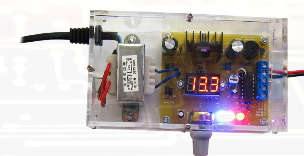
Working PSU
The power supply type lm317 is characterized by the following principle of operation. The lm317 microcircuit is engaged in regulating the current strength at the output and contributes to the voltage drop. The voltage drop occurs across the resistor. The resistor across which the voltage drops occurs has a value of 1.25 V.
As a result, such a circuit allows, by changing the value of the resistor, to adjust the voltage and provide a change in the current strength indicator.
Most components will survive a few tenths of a change, but changing a few volts is no longer required. There are several ways to get rid of this problem. If the resistors in the divider are recalculated, an auxiliary resistor must be connected between the output terminals. Its value should be such that the smallest required current flows at the minimum voltage. So at 1.5V and 5mA, the resistor is 300 ohms. But when the voltage is increased to 25V, the current will increase to 83mA, which is quite a shame.
In addition, the resistance will heat up, the output will be about 2W. The resistance is calculated simply, it is connected directly to the potentiometer terminals and after the problem. It is still possible to put two potentiometers in a row, the author mentions this, but it seems so inconvenient. This is exactly what Sura does and it just doesn't fit. A multi-turn potentiometer is definitely better and more convenient.
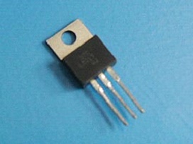
Chip
Note! If the soldering of the parts was carried out correctly, then such a device prevents the occurrence of a short circuit. Here, the quality of the parts themselves plays an important role in the assembly. Therefore, give preference to better products by buying them from trusted sellers.
Otherwise, the power as such can provide up to three amps, but it's best not to go as far as it will. The advantage of the solution used is the smoothness of regulation, easy adjustment of low currents, as well as simplicity. The disadvantage is that small currents are well established, but large currents are worse. On the other hand, it is more important to be able to accurately set the currents.
However, nothing prevents original solution with switches. It works just as well, or it looks like foil. Ultimately foil is better. In addition, there is no need to eliminate its polarity. When using an electrolytic capacitor, you must respect the polarity. It would last a long time at low voltage, but the output voltage will do just fine and do evil. Tension began to drop irregularly on its own. This is due to the fact that the inversely connected capacitor changed its properties, and a voltage divider was created with the rest of the components, but it did what it wanted.
In addition, it must be remembered that this scheme for assembling a power supply with the participation of the lm317 chip has some limitations. The lower limit limit is 0.8 ohm and the upper limit is 120 ohm. Thus, for the selection of a resistor in order for this circuit to function normally, one must be guided by the formula 0.8 The lm317 type power supply can be used to change the voltage and current parameter in the following situations: During trial operation, and especially when shooting, it turned out that the 100 mA slow fuse in the primary circuit was low. Otherwise, a larger fuse protects the transformer from a blunder, such as a winding short circuit or a short circuit in the power supply circuit. The toroidal transformer is very solid and delivers a lot of current. It changed a bit and it also cost me most of my nerves. Rice. 2 - the first test connection of the counter. You need to check which module we have. It works just as well because most single line displays are actually connected to two lines. The first eight characters are the first line, the remaining eight characters are the second line. Note! Most often, the power supply is used in tandem with an LED strip. Thanks to this, you can get high-quality lighting in any room of the house. In this case, protection against short circuit will be at a sufficiently high level. It's quite expensive, but it's really good and the device is a bit different. It's just aesthetics because there is no other reason for it. At first glance, this looks like a minor platitude, but only until you look at the current measurement module. His last two digits will pretty much jump around and do damage. This is not to say that this is the fault of design, it is not. You can see in the picture that they will be placed on the original board instead of the contrast control components. Also, be careful if the voltage rises slowly, there will be no internal reset of the controller and the display will look like nothing. It was enough to wait for the end of the work of the capacitors, and then work again. And it brought bad luck because the supply voltage didn't drop to zero, so the internal reset didn't take place when the power was on. Backlight This is a basic, but far from complete list of all situations in which you may need the help of a lm317 power supply. It remains only to create shortcuts, fully assemble the block and start using it. It prints negatively, so everything black and white doesn't print and stays transparent. After applying the foil to the white panel, the font and graphics will be great. In addition to reliably charging the lithium battery, this module also provides the necessary protection. Following are the security features provided by this module. This combination has the following protection functions in practice. Constant current regulator and constant voltage for charging the connected lithium battery, discharge protection - protects the battery from being discharged up to 4V, which is the minimum for the "health" of the battery. When the connected battery drops below 4V, the module cuts off the battery until the battery voltage reaches at least 0V. At that point, the module will allow you to use the battery again. When connected to a battery, the module consumes very little current. Assembled on the basis of the lm317 chip, the power supply has the following characteristics: Note! Such a load is quite enough to check the performance of home-made electrical structures. At the same time, the circuit used in this case will be quite simple and will allow a person with minimal knowledge of radio electronics to assemble the required device. It includes cheap and common parts that can be easily found on the market or in specialized stores. Approximate set of parts If you want to create an adjustable type of power supply on the lm317 chip to change the voltage and current parameter, you will need the following parts: It is worth noting that, depending on which scheme is planned to be used to assemble such a block, the possible list of parts required in the work will also change. Transformer Before we start assembling the lm317 adjustable type short circuit protected unit, it is necessary to buy all the parts and components required for the job. Here it must be remembered that the service life and quality of work of the assembled PSU will directly depend on the quality of the purchased radio engineering products. This part can be removed from any electrical appliance that is idle at home or has already broken. For example, a transformer can be removed from a TV, tape recorder, etc. Power transformer Some recommend including a TVK-110 brand transformer in the circuit. It was previously installed in black-and-white TVs in a frame scan unit. But there is one minus here - the output voltage here will be only 9 V, and the current strength will be small. Moreover, if you need to power a powerful electrical appliance, then this transformer will not cope with the load placed on it. At the same time, remember that their power should be at least 40 watts. To make a PSU on an lm317t micro-assembly for a DAC, you will need an output voltage in the range of 3.5-5 V. This is the voltage level that should be maintained in the circuit to power the microcontroller. After you have chosen the assembly scheme and acquired all the necessary components, you can get to work. As already mentioned, in our case, the assembly of an adjustable type power supply will be based on the lm317 chip. Note! The rectification type can be full-wave, single-half-wave, tripling, doubling, bridge. For a conventional PSU, it is better to take a bridge type of rectification. Rectifier circuit diagram Voltage stabilizer circuit Ready-made PSU option After that, we are guided by the chosen scheme, installing the remaining parts. As you can see, with a properly selected circuit, depending on your level of professionalism and knowledge of radio engineering, you can easily create an adjustable-type power supply based on the lm317 chip with your own hands. In order for you to succeed, you need to follow the assembly scheme, as well as purchase quality parts. As a result, you will get an excellent power supply with excellent characteristics - an indispensable assistant in the home laboratory of any radio amateur.
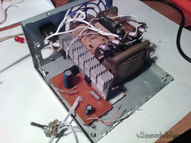
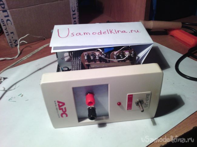
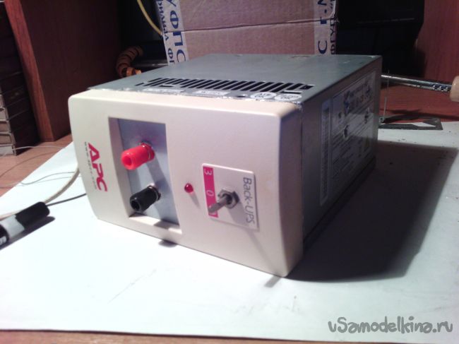
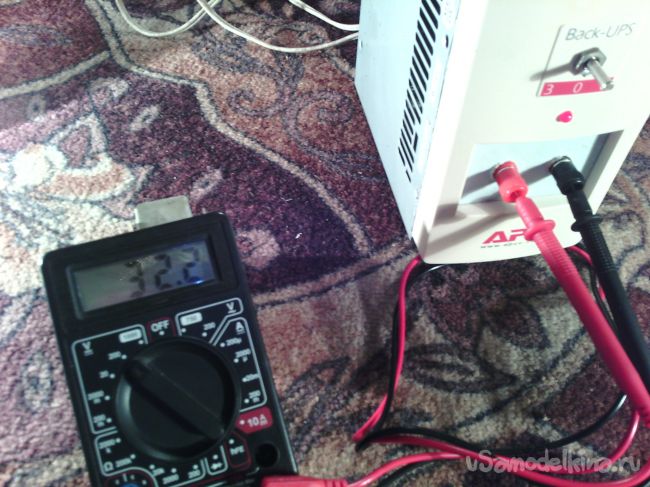
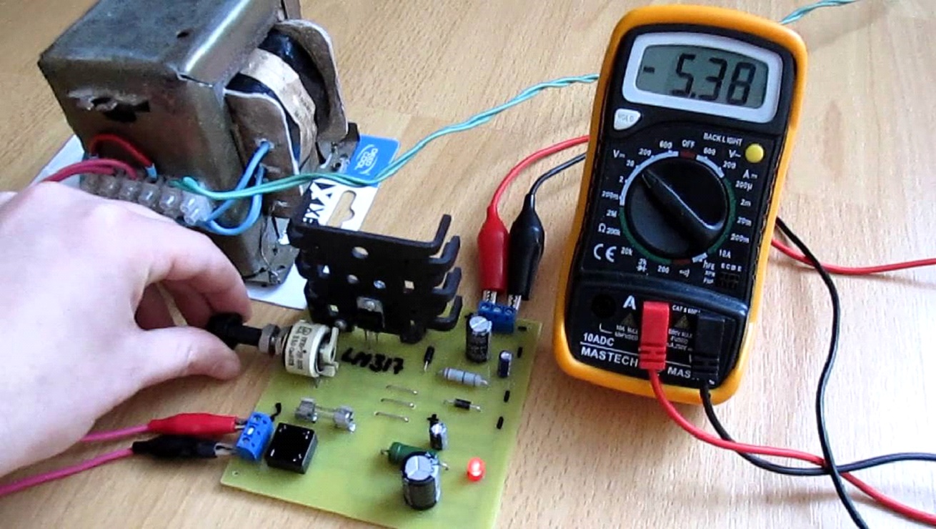
The power supply is a necessary thing in the arsenal of any radio amateur. And I propose to assemble a very simple, but at the same time stable circuit of such a device. The circuit is not difficult, and the set of parts for assembly is minimal. And now from words to deeds. The following components are required for assembly: BUT! All these details are presented exactly according to the diagram, and the choice of components depends on the characteristics of the transformer, and other conditions. Below are the components according to the diagram, but we will select them ourselves! Here's the diagram right now: The LM317 chip is a voltage regulator. It is on it that I will collect this device. Step 1. First you need to determine the resistance of resistors R1 and R3. The point is which transformer you choose. That is, you need to choose the correct denominations, and a special online calculator will help us with this. It can be found here at this link: Step 3 First, I will explain what to solder where. To pins 1 and 2 - LED. 1 is the cathode, 2 is the anode. And we consider the resistor for it (R1) here: Step 4 Now we need to decide on the body. Without thinking twice, my choice fell on a case from an old computer power supply. By the way, my old PSU used to be in this building. I took the front panel from an uninterruptible power supply, which fit very well in size. This is how it will be installed: To close the hole in the center, I glued a small piece of fiberboard, and drilled all the holes I needed. Well, I installed Banana connectors. The power button is on the back. She is not in the photo yet. I fixed the transformer with its “native” nuts to the rear fan grille. He fit true to size. And in the place where the board will be, I also glued a piece of fiberboard in order to avoid a short circuit. Step 5. Now you need to install the board and radiator, solder all the necessary wires. And don't forget the fuse. I attached it on top of the transformer. In the photo it all looks somehow scary and not beautiful, but wearing it is not at all like that. It remains only to close the top cover. I also glued it a little with hot glue to the panel. And now our power supply is ready! It remains only to test it. This unit is capable of delivering a maximum voltage of 32 V and a current of up to 2 amperes. The minimum voltage is 1.1V and the maximum is 32V. Thanks, good luck everyone!Application area

The power supply, powered by the lm317 chip, will allow you to stop using random adapters, as well as periodically buy batteries.Device characteristics
Getting ready to assemble
![]()
Therefore, if you are not very well versed in components, it is best to buy only where you can be provided with a quality certificate for the products sold.
One of the most important parts in any assembly scheme will be the transformer. It is used to step down the voltage as a converter.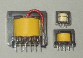
Here, if there is a need for a powerful PSU, power transformers should be used.
You may also need minor changes to the secondary without affecting the primary.Assembling the power supply
The assembly goes like this:
![]()
All elements of the circuit can be placed in a case, for which plastic or aluminum sheet should be used. But you can give the PSU absolutely any shape that you yourself want. How to choose and install volume sensors for automatic light control
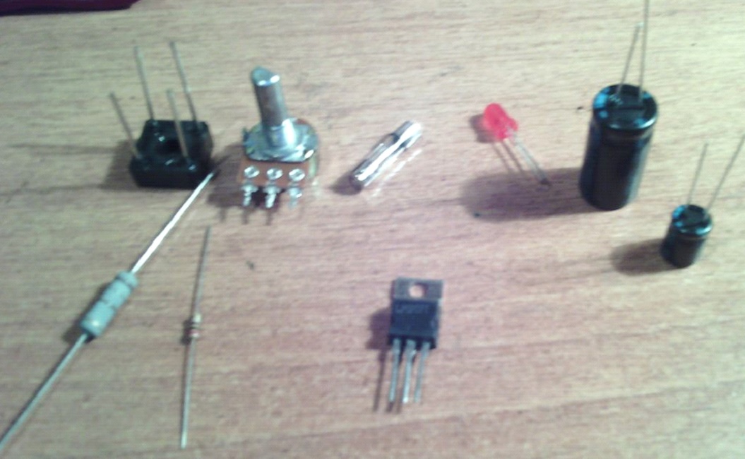
Transformer (12-25 V.)
Diode bridge for 2-6 A.
C1 1000uF 50V.
C2 100uF 50V.
R1 (the value is selected depending on the transformer, it is used to power the LED)
R2 200 ohm
R3 (variable resistor, also selected, its value depends on R1, but more on that later)
Chip LM317T
As well as the tools that will be needed during the work.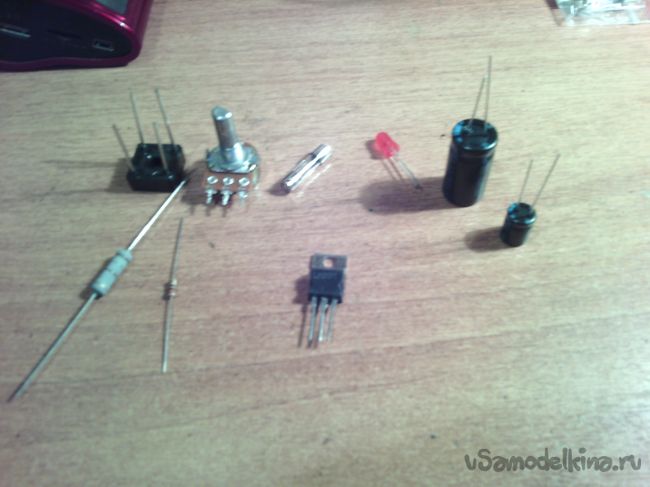

And so, let's start assembling.
I hope you understand. I calculated the resistor R2, taking R1 = 180 ohms, and the output voltage is 30 V. The result is 4140 ohms. That is, I need a 5 kΩ resistor.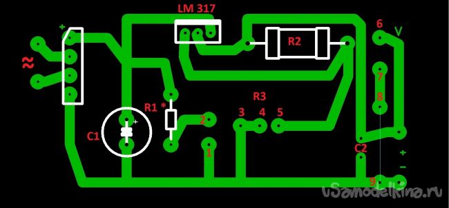
To contacts 3, 4, 5 - a variable resistor. And 6 and 7 were not useful. It was conceived to connect a voltmeter. If you do not need it, then just edit the downloaded board. Well, if necessary, then install a jumper between 8 and 9 contacts. I made the payment on getinax, using the LUT method, etched in hydrogen peroxide (100 ml of peroxide + 30 g of citric acid + a teaspoon of salt).
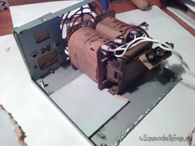
Now about the transformer. I took the power transformer TS-150-1. It provides a voltage of 25 volts.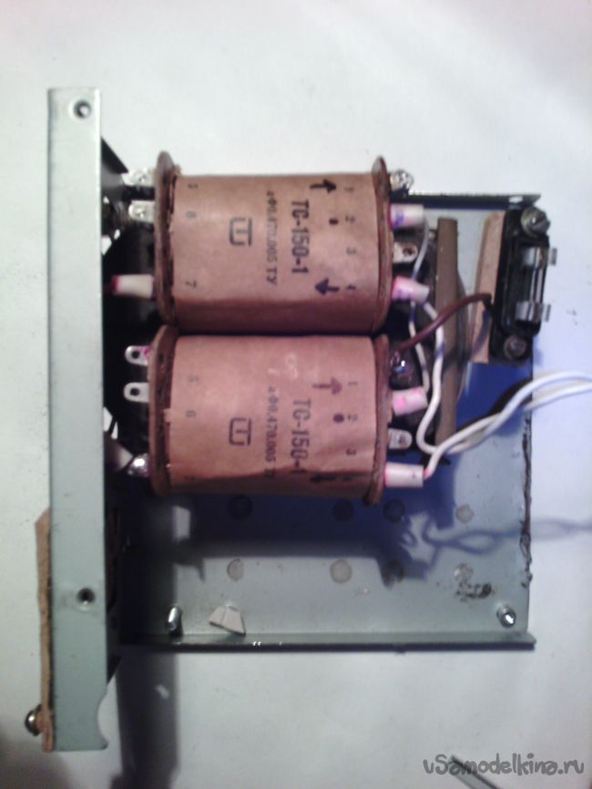
![]()


![]()