How to check insulation with a megohmmeter.
An integral part and indicator of the electrical network is such a thing as isolation. Wire or cable sheath, electrical insulator overhead line, transformer terminal insulator and other devices prevent electric current contact where we do not need. The insulating sheath provides protection against short circuit, fire, breakdown on the body of an electrical device or machine, as well as protecting a person from electric shock. However, the insulation is affected external factors such as time, sun, frost, water, mechanical wear, contact with aggressive media. To detect a defect in time, there is a device - a megohmmeter. How to use this device, we will describe further, providing a method for measuring insulation resistance with a megohmmeter.
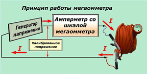
The principle of operation of the device
Operating Instructions
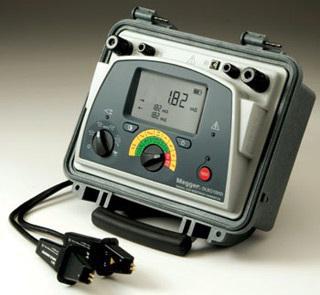
At present, digital measuring instruments have become widespread due to their compactness and lightness, but pointer models with a manual dynamo still go along with them. Now we will consider how to properly use the old-style megger and the new one.
We draw your attention to the fact that some people call the device for measuring insulation resistance a megger. This is not quite the right name, because. if you break the word into parts, you get the prefix "mega", the unit of measurement is "ohm" and "meter" (translated from Greek as a measure).
User manual
Checking the insulation resistance is carried out on de-energized equipment or cable line, electrical wiring. Be aware of what the device generates high voltage and in case of violation of safety measures for the use of a megohmmeter, electrical injuries are possible, tk. Measuring the insulation of a capacitor or a long cable line can lead to the accumulation of a dangerous charge. Therefore, the test is carried out by a team of two people who have an idea about the danger of electric current and have received a safety clearance. During the test of the object, no unauthorized persons should be nearby. Be aware of high voltage.
Each time the device is inspected for integrity, for the absence of chips and damaged insulation on the measuring probes. Trial testing is carried out by testing with divorced and closed probes. If tests are carried out with a mechanical device, then it must be placed on a horizontal, even surface so that there is no measurement error. When measuring insulation resistance with an old-style megohmmeter, you need to rotate the generator knob at a constant frequency, approximately 120-140 rpm.
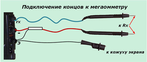
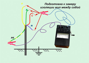
If you measure resistance relative to the case or ground, two probes are used. When testing the cable cores relative to each other, you need to use the “E” terminal of the megohmmeter and the cable screen to compensate for leakage currents.
The insulation resistance does not have a constant value and largely depends on external factors, so it may vary during the measurement. The check is carried out for at least 60 seconds, starting from 15 seconds, readings are recorded.
For household networks tests are carried out with a voltage of 500 volts. Industrial networks and devices are tested with voltage in the range of 1000-2000 volts. What kind of measurement limit to use, you need to find out in the operating instructions. The minimum allowable resistance value for networks up to 1000 volts is 0.5 MΩ. For industrial devices, no less than 1 MΩ.
As for the measurement technology itself, you need to use a megohmmeter according to the method described below. For example, we took the situation with the measurement of insulation in the SC (power shield).
So, the procedure is as follows:
1. We take people out of the checked part of the electrical installation. We warn of the danger, we hang out warning posters.
2. We remove the voltage, completely de-energize the shield, the input cable, take measures against erroneous voltage supply. We hang out a poster - DO NOT INCLUDE, PEOPLE WORK.
3. We check the absence of voltage. Having previously grounded the conclusions of the object under test, we install the measuring probes, as shown in the megohmmeter connection diagram, and also remove the grounding. This procedure is carried out with each new measurement, since nearby elements can accumulate a charge, introduce an error in the readings and pose a danger to life. Installation and removal of probes is carried out by insulated handles in rubber gloves. Please note that the insulating layer of the cable must be cleaned of dust and dirt before checking the resistance.
4. Checking the insulation input cable between phases A-B, B-C, C-A, A-PEN, B-PEN, C-PEN. The results are recorded in the measurement protocol.
5. We turn off all machines, RCDs, turn off the lamps and lighting fixtures, disconnect the neutral wires from the zero terminal.
6. We measure each line between phase and N, phase and PE, N and PE. The results are recorded in the measurement protocol.
7. If a defect is found, we disassemble the measured part into its constituent elements, look for a malfunction and eliminate it.
At the end of the test with portable grounding, we remove the residual charge from the object, by means of a short circuit, and the measuring device itself, discharging the probes among themselves. Here, according to such instructions, it is necessary to use a megohmmeter when measuring the insulation resistance of cable and other lines.
Today we’ll talk about another useful device that is used to measure insulation resistance, mostly large values,. It is called a megger, and you may also come across the name "megger", this name is not official, rather slang, but is also widely used. According to GOST, it is not permissible to use it in official documents. Most often, the device is used to measure the insulation resistance of various cables. With it, you can measure the resistance of not only cables, but also transformers, windings, various connectors, and much more.
Probably, you rightly had a question about what is the difference between the device and the more familiar ohmmeter. Megohmmeter measurements are made at high voltages, from one hundred to 2500 volts, which the device itself generates.
If we turn to the structure of the device, we will see that it consists of two main parts: it is a source for current constant value and a circuit for measuring voltage. Moreover, the device is portable. I must say that megohmmeters are used for various purposes, producing various voltage indicators. So, if you look at how the insulation resistance is measured with a megohmmeter, a megohmmeter for a voltage of 2500 volts is better suited for this.
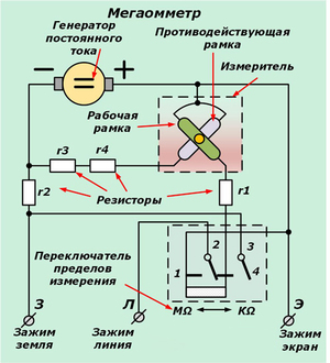
But let's get back to the device. For clarity, you can see it in the diagram below.
g is the resistance, G is the generator direct current, I - meter, P - switch of measurement limits, 3, L, E - clamps "ground", "line", "screen"; 5 - counteracting frame; 6 - working frame.
And now let's see how measurements are made and made with a megohmmeter.
Firstly, the labor protection rules for the operation of electrical installations state that only specially trained employees working as electricians can make measurements with this device. If the voltage exceeds a thousand volts, a special outfit must be issued for the measurement. At lower voltage values, it is permissible to carry out measurements within the framework of current operational work.
When measuring resistance with a megohmmeter, live parts must be disconnected and grounded. After connecting the megohmmeter, the ground can be removed.
The rules also mandate the use of dielectric gloves when measuring resistance with a megohmmeter. When you connect a megger to live parts, do not touch them. After measurements, they must be grounded for a short time to remove the residual charge. All measurement results are recorded in a special log, an example of which can be found below.
What other points should be taken into account when working with a megaohmmeter?
First of all, it is worth remembering that the data on the insulation resistance are not immutable. The fact is that they are significantly affected by temperature and humidity at the time of measurement.
The voltage of the megger should be selected according to the rated voltage of the winding. So, for example, if the rated voltage of the winding is less than 500 V, a 500 V device should be selected. For a winding voltage of less than three thousand volts - 1000 volts, and for a higher voltage - a device for 2500 volts.
In order to determine the degree of moisture content of the insulation, the indicators are recorded in dynamics: at the fifteenth second of the measurement and one minute after the start of the measurement. Based on the ratio of these two indicators, the so-called absorption coefficient is calculated. If the humidity of the insulation is high, the coefficient will be equal to one. If low, the two values will differ by 35-50%.
Before starting measurements with a megohmmeter, pay attention to the serviceability of the device. So, the arrow should point to the "infinity" mark. If this is not the case, the device should be additionally checked before starting measurements. Also carefully inspect the wires for connection. They should be long enough, flexible and well insulated. If the wires are not insulated, but a braid is used, this device is considered to be of poor quality, since such wires are easily affected by moisture. And of course, the megger itself must be dry and with a clean surface.
Do not forget to make sure that the installation is de-energized before starting the measurement (by the way, if when you install the megohmmeter, the arrow moves, this is a danger signal, which means that the voltage remains).
Also note that most often two people with the appropriate tolerances participate in the measurements.
How is the measurement itself made? To do this, the device drive handle is turned at a uniform speed (it should be approximately 120 revolutions per minute, to obtain more reliable readings, it is better to use a special automatic drive, rather than turn it manually). And at the right moments - at the fifteenth second and after 1 minute - they look at the readings of the instrument's pointer.
In some cases, such readings are taken twice. But for this it is necessary to completely discharge the settings again in order to avoid overestimated values. To do this, the installation must be grounded for at least two minutes.
Similar materials.
The reliability and functionality of power supply systems for building objects is always determined by the quality of the resistance of insulating materials. Every master should know about such important properties of the equipment. According to existing rules exploitation electrical appliances they need to be checked from time to time. Measurement of insulation resistance is always carried out using a megohmmeter.
What affects the quality of insulation?
The period of use of electrical cables, as well as their coatings, is not infinite. Insulation quality can be affected by factors such as natural light, increased voltage, differences temperature conditions, hard-to-detect damage, and the environment in which the wiring is used.
What is it for?
Measurement of insulation resistance with a megohmmeter is required for the most accurate determination of possible damage in an electrical circuit. The choice of rated current depends on the voltage supplied to the winding.
Measurement of insulation resistance is needed to test the degree of its functionality. As a result of detecting damage to the wire coating, unwanted malfunctions in the operation of equipment, as well as fire hazard situations, may occur. After a visual determination of wiring insulation defects, you can not call a specialist measurer. If you detect in time the difference between the megohmmeter readings and the set values, you can prevent a variety of accidents, premature wear of equipment, short circuits, fires, as well as injuries among maintenance personnel.
The necessary conditions
Measurement of cable insulation resistance is carried out indoors at permissible temperatures from +15 to +35 °C. Humidity should not exceed 80%. it standard conditions, which may vary depending on the device manufacturing technology. Data electrical resistance in measuring circuits must exceed the permissible value by at least 20 times.
What devices are used?
Measurement of electrical insulation resistance can be performed by devices of various configurations. They must be in working condition and have documents confirming their quality. Gosstandart bodies regularly monitor the accuracy of this type of equipment. Batteries or integrated generators can be placed inside the megohmmeters as power sources.
There are devices with different degrees of power. Devices for 1 kV are used when working with wiring, the cross section of which does not exceed 16 mm².
Generally accepted measurement standards
The first measurement of insulation resistance is carried out at the factory after wire production. The following testing is carried out at the construction site before starting the installation work and before activating the power supply systems. The last check makes it possible to determine the occurrence of problems during the installation of electrical appliances.
Interaction objects
With the use of this type of device, any electrical equipment can be measured. Devices with an operating voltage of less than 60 V are not included in this list.
Who can be trusted with the measurement?
An appropriate permit is required to perform such work. Only qualified personnel who are part of the electrical repair teams may take measurements. All of them must be prepared, undergo special training and receive appropriate certificates that determine their professional suitability.
What does resistance depend on?
Insulation resistance measurement cable lines must be carried out before and after their repair. Mainly, the temperature indicator can affect the resistance of the insulating sheaths of wires. The higher the resistance value, the smaller the cross section of the cable should be. The type of material for the manufacture of conductors also plays a role.
If we consider steel wires as an example, then their resistance index will be greater than in aluminum wire. The humidity of the surrounding air can also affect the conductivity of insulating materials. For this reason, when the specified value fluctuates, the attenuation changes.
Method of measurement
There should be no voltage in the network under test. You will need to set the maximum possible value in the section before the start. If network elements have a low isolation limit, they must be closed or disconnected. This procedure is carried out using semiconductor devices and capacitors. After that, it is necessary to ensure the grounding of electrical circuits. Measurement of insulation resistance is carried out within a minute. It is necessary to turn the knob of the integrated generator or, if the device is powered by the mains, press the "high voltage" key. Readings must be taken from the scale of the device. The electric charge is removed from the circuit by the grounding method after the end of the measurement procedure.
The value of these parameters is directly related to what the wiring lines are used for. The resistance of a wire rated for 1 kV should not exceed 0.5 MΩ. Various fixtures for control and protection must differ by this value.
Optimal resistance performance
The size of the insulating shell must be changed in accordance with the norms and requirements in accordance with the PUE. The resistance must meet the standards throughout all seasons with a decrease and increase in the required values in accordance with changes in ambient temperature.
At what interval is the resistance checked?
Standards of time after which planned measurements of certain parameters should be carried out, as well as required voltage insulation resistance measurements are described in more detail in the PTEEP documentation. Every year, the insulation resistance of lighting devices, crane and elevator wiring is checked. In other cases, it happens every few years. Portable welding and electrical equipment is checked every six months.
The chance of various kinds of unwanted breakdowns may increase if these requirements are not met. Violators may be subject to appropriate sanctions in the form of fines. All organizations should plan dates for such measurements. In this case, one should rely on technical requests and features that the equipment and each cable line must necessarily comply with. Measurement of insulation resistance is carried out during operational tests.
Safety requirements
It is impossible to start measurements without making sure that there is no voltage on the objects. Before starting the measurement, you need to make sure that there are no personnel working on those parts. electrical installation to which the test instrument is attached. Touching current-carrying elements should be prohibited for employees who are in close proximity to them. This definitely needs to be controlled.
Resistance measurement should always be carried out only on discharged current-carrying sections with preliminary grounding, which is removed after the megohmmeter is connected. Special insulating holders serve to protect current-carrying elements while using a megohmmeter to measure resistance. Do not touch the wires while connecting the device. The method of short-term grounding removes the residual charge from current-carrying parts after completion of work. Measurements should be carried out repeatedly for the entire period of operation. electrical networks. This procedure requires responsibility. Early measurement of electrical wiring insulation resistance makes it possible to prevent the occurrence of unforeseen emergencies at enterprises.
Required Documentation
The accompanying act of measuring the insulation resistance of electrical wiring is drawn up before performing work. The date of the measurements is set. Then the name of the settlement is indicated, in which a team of measuring specialists was involved. Next, you must specify the name of the object or organization where the measurement work was carried out, its address and contact details. The name of the project is indicated, as well as the number of the contract. All members of the commission confirm their presence with their signatures and surnames.
The name of the device, number, class, type and scale are indicated. The note field is filled in as needed. Then the measurement data are given: wiring marking according to the drawing, cross section and number of cores, insulating resistance with respect to earth and between wires. The size and method of withdrawal of the commission are indicated, as well as the initials, position and all signatures of its members.
Registration of results
The test results are always recorded in the insulation resistance measurement protocol. A list of identified deficiencies must be presented to customers for appropriate action to be taken to eliminate them. Documentation in the form of electronic files must be stored in appropriate databases. Another copy should be printed out and placed in the archives of electrical laboratories. Copies of measurement and test protocols shall be kept for at least three years.
Actions in case of unsatisfactory result
In case of discrepancies between the documentation and the work performed, the members of the working commission will not sign the act. The corresponding conclusion is presented to the head. After that, the commission draws up a list of identified defects and indicates the name of the organization responsible for their timely elimination, which must correct the discrepancies within 10 days. Workers are required to deal with the elimination of the malfunctions that have arisen according to the instructions. They fix breakdowns and do everything according to the rules. The insulating material must be in good condition, not conducive to ignition. After that, it is necessary to submit the act of the working commission again for re-verification. With full consent, all participants put their signatures.

Conclusion
Megaohmmeters are very convenient to use. All measurement data will be displayed on the digital display. Ergonomics of modern devices is significantly different from the samples of the last century. Measurements are carried out simply and easily. Megaohmmeters are distinguished by their versatility and a fairly wide frequency range.
AT electrical circuits the most important role is played by the insulation resistance. This is especially important for high voltage installations. Industrial current voltage 230/400V (220/380V by outdated standards) can be considered high from the point of view of safety without a doubt. Therefore, the insulation resistance test of electrical installations is always performed:
- when putting the electrical installation into operation;
- after completion of repair work;
- periodically for prevention.
For such tests, a special device is used - a megohmmeter. From its name it follows that it measures resistance in millions of ohms. Therefore, work with a megohmmeter is carried out using high voltage. Otherwise you can't get electric field, close to real conditions, and a weak leakage current cannot be measured by existing devices.
You need to know how to use a megohmmeter, this device requires tolerance group 3 and higher for electrical safety. At the output terminals of the device at the time of measurement, there is a high voltage of the order of 500-2500V. When measuring the insulation resistance of cable and other lines with a megohmmeter, or when the absorption coefficient is measured, a significant charge accumulates in the conductor, since the capacitance of long conductors can reach several mF.
The insulating material has permittivity which increases the capacity. Careless touching of such a conductor AFTER checking the insulation can be deadly! Since not everyone, even electricians, are amateurs and connoisseurs of physics, the literal knowledge of the instructions for working with a megohmmeter is mandatory and is checked, regardless of education and qualifications, by all workers who receive a permit for the right to take measurements.
The rules define how to measure the insulation resistance in each specific case. Measuring insulation resistance with a megger is the action for which it is intended. For example, measuring the insulation resistance of an electric motor or the absorption coefficient. On the other hand, it is preferable to measure the resistance of DC windings with another device (an ohmmeter, and preferably a DC bridge), although a megohmmeter can operate in the low resistance range, the results will be rough. You can only ring the conductor with a megohmmeter - in this case it will show zero resistance or very close to it.

Megaohmmeter device
Modern megohmmeters have a device that differs significantly from the devices of early samples, however, the principle of their operation remains the same: supply to the measuring circuit increased voltage and measuring the small currents that flow in this circuit. Instead of a dynamo machine and a pointer galvanometer placed in a massive carbolite case, modern appliance contains a high-voltage pulse generator, a rectifier, a digital microammeter, a control controller and a display for displaying measurement results.
For power, alkaline or lithium-ion cells are used, with a total voltage of 9-12 V. It is these devices that have now become widespread. Devices of obsolete types due to physical aging may simply not pass verification and will not receive a certificate. Without this document, measurements are considered invalid.
Modes and norms of measurements
For household wiring and electrical installations, insulation resistance tests of wires are carried out with a voltage of 500 V, and for industrial ones with a voltage of 1-2.5 kV. The minimum insulation resistance of household networks and installations should be at least 0.5 MΩ, and industrial networks should be at least 1.0 MΩ, hence the difference in voltages required for a megohmmeter.
Cable and wiring insulation
Measurement of cable insulation resistance is carried out between its conductors and between individual conductors and the ground or screen (casing), if any. If the cable has a screen or braid, then it is connected to the “E” terminal of the megohmmeter to compensate for leakage currents when measuring insulation between conductors. If the device under test is a cabinet, then the case is connected to the “E” terminal. The cable shield, sheath, jacket or housing of the electrical installation is always earthed. To connect the device, use only insulated wire. It is forbidden to touch it with your hands during measurements. The tested conductor after testing is grounded by the conductor using an insulating rod.
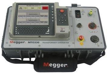
Insulation of electric motors and transformers
 Since both the motor and the transformer are considered electrical machines, there are many similarities in how the insulation resistance of a transformer and a motor is measured. The electric motor (transformer) is tested for interwinding insulation resistance - insulation between phases, as well as for insulation resistance between each of the windings and the housing. In the event that the windings are connected in a star or delta internally, then only the resistance between the windings and the housing is tested. In electric motors, tests of bearing insulation can be additionally carried out.
Measurement safety
Measurements with a megohmmeter always report charges to insulated conductors, and than better quality isolation, the longer the charge lasts. For safety reasons, these charges must be removed using wires with insulated handles. The connection points of the wires from the device are short-circuited and each of the conductors is additionally shorted to ground. The goal is the same - to remove all residual charges for the safety of people.
Measurement of the insulation of electrical installations is easier to perform than lines and networks, due to the concentration and proximity to personnel. The following is a step-by-step procedure for measurements on lines.
Insulation measurements on lines
When preparing for measurements of cable lines, it is necessary to remove strangers and animals from all places where access to conductors is possible. Hang warning signs and put on duty.
The line must be completely de-energized and disconnected from all loads: automatic devices, RCDs, inserts, all plugs must be removed from sockets, etc. otherwise, it will be impossible to measure the cable insulation resistance, and some devices that are in the load may be damaged.

Having chosen the circuit for measurement, first short-circuit its conductors to the ground or the case for a while (if it is already known that the grounding resistance of the case is normal). This is required for the removal of residual charges and measurement accuracy.
Measuring device(megaohmmeter) is securely connected to the selected points between which the insulation is tested. Screens, braids and housings are connected to the "E" terminal. The insulating material of the megohmmeter wires must be intact along their entire length.
The "Start" button is pressed and voltage is applied to the line. After 15 seconds, the first reading of the insulation resistance is automatically taken. After another 45, the second is done. The device calculates the absorption coefficient. This is the ratio of the second count to the first. The absorption coefficient gives a measure of the moisture content of the insulation.
The polarization coefficient is measured for 600 seconds. This is the third count. The ratio of the third reading to the second is the polarization coefficient. This is a measure of the quality of the insulation.
The measurement process carried out is stored in the megaohmmeter and all data can be displayed or stored in memory (this depends on the brand of the device).
The megohmmeter is turned off, using isolated rods and a special conductor discharge the line conductors through the measurement circuit and to the ground. The steps are repeated for all necessary circuits.
Evaluation of results
For small objects, the insulation resistance is considered to be the data obtained after 15 seconds. The screen is not used because the capacitance is small (for example, an electric motor that is not connected to a long cable.) The absorption coefficient is also not measured. In all other cases, and for cable lines, the insulation resistance is considered to be the data obtained after 60 seconds. The polarization index is measured during complex tests of electrical installations.
Readers of this article will most likely need to measure small objects, where the insulation measurement is made using a simplified version. Megaohmmeters allow you to select the required measurement modes in your menu, since all measuring procedures are more or less standardized. Despite this, we must not forget for a second about the observance of the security measures that are listed in the article!
Electrical networks are characterized by various parameters. One of the most important network parameters is electrical isolation. Insulation is any material that prevents electrical current from flowing in the wrong direction. Insulation can be a protective sheath of wires and cables. Devices such as insulators prevent the conductive lines from contacting the ground. All these measures for isolating conductive parts are aimed at preventing a short circuit, fire or electric shock to a person.
Megaohmmeter
Insulation, like any other material, is affected by various external factors: weather, mechanical wear, and others. For the timely detection of an insulation defect, there is a device, the so-called megaohmmeter. It measures the insulation resistance.
The principle of operation of the device
What the device is intended for can be understood from its name, which is formed from three words: "mega" - the dimension of the number 10 6 "ohm"- unit of resistance and "meter" - to measure. A megohmmeter is used to measure electrical resistance in the megaohm range. The principle of operation of the device is based on the application of Ohm's law, from which it follows that the resistance (R) is equal to the voltage (U) divided by the current (I) flowing through this resistance. Therefore, in order to implement this law in the device, we need:
- DC generator;
- measuring head:
- terminals for connecting the measured resistance;
- a set of resistors for the operation of the measuring head within the working area;
- a switch that switches these resistors;
 The implementation of a megohmmeter according to this scheme requires a minimum of elements. She is simple and reliable. Such devices have been working properly for half a century. The voltage in such devices is produced by a DC generator, the value of which is different in different models. Usually it is 100, 250, 500, 700, 1000, 2500 volts. In various models devices, one or more voltages from this range can be used. Generators differ in power and, accordingly, in size. These generators are manually operated. To work, you need to turn the handle of the dynamo, which generates direct current.
At present, digital devices are replacing electromechanical devices. In such devices, either galvanic cells or batteries are used as direct current sources. And there are also new models with built-in AC adapter.
Working with a megaohmmeter
 Work on any equipment with this instrument is classified as work with heightened danger due to the fact that the device generates high voltage and there is a possibility of electrical injury. Operations with this device it is allowed to carry out by personnel who have studied the instructions for working with the device, according to the rules of labor protection and safety when working in electrical installations. The employee must have the appropriate access group and periodically undergo tests for knowledge of the rules of work in electrical installations, know the instructions for labor protection, including the use of a megohmmeter.
Typically, this device measures the insulation resistance of cable lines, electrical wiring and electric motors. Devices must be periodically checked in the metrological service and have the appropriate documents. It is forbidden to take measurements with an untested device; it must be withdrawn from operation and sent for testing.
 Before starting work using a megohmmeter, you need to verify the integrity of the device by visual inspection. It should have a verification stamp, there should be no chips on the instrument case, the indicator glass should be intact. Checked measuring probes for insulation damage. You need to test the device. For this, it is necessary, if a pointer device is used, to install it on a horizontal surface in order to avoid measurement errors and to take measurements with divorced and closed probes.
On older models of megohmmeters, measurements are carried out by rotating the generator handle at a constant frequency of 120–140 rpm. On other models, measurements are made by pressing the corresponding button on the device. The megohmmeter should show infinity and zero megohm, respectively. After that, you can start work on measuring the insulation resistance.
Instrument measurements
The way this type of work is done varies from company to company. In some organizations, these works are carried out according to a permit, in some by order or in the order of current operation. Important, that general rules execution are the same. Take, for example, the technology of measuring the insulation resistance of communication cables in railway transport. Having completed all the necessary organizational and technical measures (designing the work, hanging posters, and so on), we proceed directly to the measurements.
 Having chosen the pair on which you want to make measurements, you first need to check the absence of voltage on it. With the help of previously prepared grounding conductors, we remove the charge from the measured cable cores and ground them. Having installed the measuring probes and removed the ground electrodes, we measure the insulation resistance with a megohmmeter. Having fixed the results obtained, we switch the measuring probe to another core and repeat the measurement procedure.
It must be remembered that after measurements, an electric charge remains in the cable. After the completion of measurements with the help of a ground electrode, it is necessary to remove the electric charge. It is necessary to discharge the megohmmeter itself. It's done short circuit measuring cords. Work on the installation of measuring probes and grounding conductors is carried out in dielectric gloves.
The measured value of insulation resistance is recorded in the protocol. The protocol usually indicates which device was used to measure, the magnitude of the applied voltage and the measured insulation resistance. The resistance value is different for different types tests. It is compared with the permissible value and a conclusion is made about the state of the insulation of the electrical installation.
For the performance of work on measuring the insulation resistance, you must be guided by the following data:
- electrical appliances and devices with voltage up to 50 volts tested with a megger voltage of 100 volts, the measured resistance value must be at least 0.5 MΩ. During measurements, semiconductor devices that are part of the apparatus must be shunted to prevent their failure;
- electrical appliances and apparatus with a voltage of 50 to 100 volts tested with a megger voltage of 250 volts. The results are similar to item 1;
- electrical appliances and apparatus with voltage from 100 to 380 volts tested with a megohmmeter voltage of 500–1000 volts. The results are similar to item 1;
- electrical appliances and apparatus with voltage from 380 to 1000 volts tested with a megohmmeter voltage of 1000–2500 volts. The results are similar to item 1;
- switchboards, switchgears(RU), conductors are tested with a megohmmeter voltage of 1000–2500 volts, the measured resistance must be at least 1 MΩ, and each section of the switchgear must be measured;
- lighting wiring tested with a megohmmeter voltage of 1000 volts, the measured resistance value must be at least 0.5 MΩ.
The frequency of measurements is established at the enterprises. The owners of electrical installations make decisions about further actions on the electrical installation, depending on the measurement results.
The work of measuring insulation resistance is one of the major works in electrical installations, which helps monitor the condition of electrical equipment and cable facilities and take timely measures for the trouble-free operation of the electrical facilities.
We advise you to read
, diagnosis, treatment Treatment of urogenital chlamydia") Chlamydia urogenital - description, causes, symptoms (signs), diagnosis, treatment Treatment of urogenital chlamydia
Chlamydia urogenital - description, causes, symptoms (signs), diagnosis, treatment Treatment of urogenital chlamydia The benefits and significance of hydroamino acid threonine for the human body L threonine what
 To wait or not to wait for a guy from the army For what reason can they be commissioned from the army
 Baked apples with cottage cheese Baked apples with cottage cheese

