All documents presented in the catalog are not their official publication and are intended for informational purposes only. Electronic copies of these documents can be distributed without any restrictions. You can post information from this site on any other site.
UNIFIED SYSTEM OF DESIGN DOCUMENTATION
SYMBOLS
GRAPHIC IN DIAGRAM
GOST 2.728-74
Moscow
STATE STANDARD OF THE UNION OF THE SSR
|
Unified system of design documentation CONDITIONAL GRAPHIC DESIGNATIONS IN SCHEMES. Unified system for design documentation. |
GOST
|
By the Decree of the State Committee of Standards of the Council of Ministers of the USSR dated March 26, 1974 No. 692, the introduction period was established
from 1975-07-01
1. This standard establishes the conventional graphic symbols (designations) of resistors and capacitors in circuits performed manually or automatically in all industries.
The standard fully complies with ST SEV 863-78 and ST SEV 864-78.
2. The designations of resistors for general use are given in.
Table 1
|
Designation |
|
|
1. Resistor constant Note . If it is necessary to indicate the value of the rated power dissipation of resistors, then for the range from 0.05 to 5 V it is allowed to use the following designations of resistors, the rated power dissipation of which is equal to: |
|
|
0.05 V |
|
|
0.125 V |
|
|
0.25 V |
|
|
0.5 V |
|
|
1 V |
|
|
2 V |
|
|
5 V |
|
|
2. Fixed resistor with additional taps: |
|
|
a) blue symmetrical |
|
|
b) one asymmetrical |
|
|
c) with two |
|
|
Note. If the resistor has more than two additional taps, then it is allowed to increase the long side of the designation, for example, a resistor with six additional taps |
|
|
3. Measuring shunt |
|
|
Note. The lines depicted as continuations of the short sides of the rectangle indicate the leads to be included in the measuring circuit. |
|
|
4. Variable resistor |
|
|
Notes : 1. Arrow indicates moving contact 2. Unused output is allowed not to be depicted |
|
|
3. For a variable resistor in a rheostatic connection, it is allowed to use the following designations: |
|
|
a) general designation |
|
|
b) with non-linear regulation |
|
|
5. Variable resistor with additional taps |
|
|
6. Variable resistor with several moving contacts, for example, with two: |
|
|
a) mechanically unrelated |
|
|
b) mechanically connected |
|
|
7. Resistor variable dual |
|
|
Note to paragraphs. 4-7. If it is necessary to clarify the nature of regulation, then regulation designations should be used in accordance with GOST 2.71-74;for example, a variable resistor: |
|
|
a) with smooth regulation |
|
|
b) with step regulation |
|
|
To indicate the open position, a symbol is used, for example, a resistor with an open position and step regulation |
|
|
c) with a logarithmic characteristic of regulation |
|
|
d) with inverse logarithmic (exponential) control characteristic |
|
|
e) adjustable by means of an electric motor |
|
|
8. Variable resistor with closing contact, shown: |
|
|
a) together |
|
|
b) spaced |
|
|
Notes : 1. The dot indicates the position of the movable contact of the resistor at which the NO contact is triggered. In this case, the closure occurs when moving away from the point, and the opening occurs when moving towards the point. 2. With the spaced method, the normally open contact should be depicted 3. It is allowed not to blacken the point in the designations |
|
|
9. Trimmer resistor |
|
|
Notes : 1. An unused output is allowed not to be depicted |
|
|
2. For a tuning resistor in a rheostatic connection, the following designation can be used |
|
|
10. Variable resistor with tuning |
|
|
Note . The above notation corresponds to the following equivalent circuit:
|
|
|
11. Strain gauge: |
|
|
a) linear |
|
|
b) non-linear |
|
|
12. Heating element |
|
|
13. Thermistor: |
|
|
a) direct heating with a positive temperature coefficient |
|
|
with negative temperature coefficient |
|
|
b) indirect heating |
|
|
14. Bap history |


(Changed edition, Rev. No. 1, 2).
3. The designations of functional potentiometers designed to generate non-linear non-periodic functions are given in.
table 2
|
Designation |
|
|
1. Functional single-winding potentiometer (for example, with a profiled frame) |
|
|
Note. Near the image of the moving contact, it is allowed to write an analytical expression for the generated function, for example, a potentiometer for generating a quadratic dependence |
|
|
2. Functional single-winding potentiometer with several additional taps, for example, with three |
|
|
Notes : 1. Lines depicting additional taps should divide the long side of the designation into segments approximately proportional to the linear (or angular) dimensions of the corresponding sections of the potentiometer 2. The line representing the movable contact should take an intermediate position relative to the lines of additional taps 3. Multi-winding functional potentiometer, for example, two-winding, shown: |
|
|
a) together |
|
|
b) spaced |
|
|
Note . It is assumed that the multi-winding functional potentiometer is designed in such a way that all windings are on a common frame, and the moving contact electrically contacts all windings simultaneously. |
|
|
4. Multi-winding functional potentiometer, for example, three-winding with two additional taps from each winding, shown: |
|
|
a) together |
|
|
b) spaced |
|
|
Note to pp. 3 and 4. With a exploded image, the following conventions apply: a) the movable contact should be shown on the designation of each potentiometer winding; b) the lines of mechanical connection between the designations of moving contacts are not shown; c) an electrical communication line depicting a moving contact circuit may be depicted only on one of the windings, for example, a two-winding potentiometer with series-connected windings |
|


Note . The notation set in should be used for potentiometers in which the moving contact moves between two fixed (initial and final) positions. In this case, the constructive completion of the potentiometer can be any: linear, ring or spiral (multi-turn potentiometers).
4. Designations of functional ring closed potentiometers intended for cyclic generation of non-linear functions are given in.
Table 3
|
Designation |
|
|
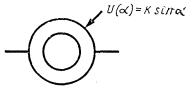
1. Functional ring closed single-winding potentiometer (for example, with a profiled frame) with one movable contact and two taps |
|
|
Note . It is allowed to write an analytical expression for the generated function near the image of the moving contact. e.g. sinus potentiometer |
|
|
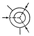
2. Functional ring closed single-winding potentiometer with several moving contacts, for example, with three: |
|
|
a) mechanically unrelated |
|
|
b) mechanically connected |
|
|
3. Functional ring closed single-winding potentiometer with an isolated section |
|
|
Note. In an isolated area, there is no electrical contact between the winding and the moving contact |
|
|
4. Functional ring closed single-winding potentiometer with a short-circuited section |
|
|
Notes . 1. On the short-circuited section of the potentiometer, the resistance is zero. 2. The annular sector corresponding to the short-circuited section may not be blackened 3. Functional ring closed multi-winding potentiometer, for example, two-winding with two taps from each winding, shown: |
|
|
a) together |
|
|
b) spaced |
|
|
Notes : 1. It is assumed that the multi-winding functional potentiometer is structurally designed in such a way that all windings are on a common frame, and the movable contact electrically contacts all windings simultaneously. 2. With a spaced image, the conventions established in the note to p.p. 3 and 4 |
|


Note . All angular dimensions in the designations (angles between tap lines, between movable mechanically connected contacts, dimensions and location of sectors of insulated or short-circuited sections) should be approximately equal to the corresponding angular dimensions in the design of potentiometers.
5. Capacitor designations are given in.
Table 4
|
Designation |
|
|
1. Fixed capacitor |
|
|
Note . To indicate a polarized capacitor, use the notation |
|
|
1a. Fixed capacitor with outer electrode marked |
|
|
2. Electrolytic capacitor: |
|
|
a) polarized |
|
|
b) unpolarized. |
|
|
Note .The “+” sign can be omitted if this does not lead to incorrect reading of the diagram |
|
|
3. Fixed capacitor with three terminals (two-section), shown: |
|
|
a) together |
|
|
b) spaced |
|
|
4. Pass capacitor |
|
|
Note . The arc indicates the outer lining of the capacitor (case) It is allowed to use the designation |
|
|
5. Capacitor reference. The lower lining is connected to the body (chassis) of the device |
|
|
6. Capacitor with its own resistor in series |
|
|
7. Shielded Capacitor: |
|
|
a) with one plate connected to the body |
|
|
b) with a conclusion from the body |
|
|
8. Variable Capacitor |
|
|
9. Multi-section variable capacitor, for example, three-section |
|
|
10. Trimmer capacitor |
|
|
11. Differential capacitor |
|
|
11a. Two-stator variable capacitor (in each position of the movable electrode С=С) |
|
|
Note to pp. 8 - 11a. If it is necessary to specify a movable lining (rotor), then it should be depicted as an arc, for example |
|
|
12. Varikond |


STATE STANDARD OF THE UNION OF THE SSR
UNIFIED SYSTEM OF DESIGN DOCUMENTATION
SYMBOLS
GRAPHIC IN DIAGRAM
GOST 2.728-74
Moscow
STATE STANDARD OF THE UNION OF THE SSR
By the Decree of the State Committee of Standards of the Council of Ministers of the USSR dated March 26, 1974 No. 692, the introduction period was establishedfrom 1975-07-01
1. This standard establishes the conventional graphic symbols (designations) of resistors and capacitors in circuits performed manually or automatically in all industries. The standard fully complies with ST SEV 863-78 and ST SEV 864-78. 2. The designations of resistors for general use are given in table. one.
Table 1
|
Name |
Designation |
| 1. Fixed resistor Note. If it is necessary to indicate the value of the rated power dissipation of resistors, then for the range from 0.05 to 5 V it is allowed to use the following designations of resistors, the rated power dissipation of which is equal to: | |
| 0.05 V | |
| 0.125 V | |
| 0.25 V | |
| 0.5 V | |
| 1 V | |
| 2 V | |
| 5 V | |
| 2. Fixed resistor with additional taps: | |
| a) blue symmetrical | |
| b) one asymmetrical | |
| c) with two |
|
| Note. If the resistor has more than two additional taps, then it is allowed to increase the long side of the designation, for example, a resistor with six additional taps |
|
| 3. Measuring shunt | |
| Note. The lines depicted as continuations of the short sides of the rectangle indicate the leads to be included in the measuring circuit. | |
| 4. Variable resistor | |
| Notes: 1. The arrow indicates a moving contact 2. An unused terminal may not be depicted |
|
| 3. For a variable resistor in a rheostatic connection, it is allowed to use the following designations: | |
| a) general designation | |
| b) with non-linear regulation | |
| 5. Variable resistor with additional taps | |
| 6. Variable resistor with several moving contacts, for example, with two: | |
| a) mechanically unrelated | |
| b) mechanically connected | |
| 7. Resistor variable dual | |
| Note to paragraphs. 4-7. If it is necessary to clarify the nature of regulation, then regulation designations should be used in accordance with GOST 2.71-74; for example, a variable resistor: |
|
| a) with smooth regulation | |
| b) with step regulation |
|
| To indicate the open position, a symbol is used, for example, a resistor with an open position and step regulation | |
| c) with a logarithmic characteristic of regulation | |
| d) with inverse logarithmic (exponential) control characteristic | |
| e) adjustable by means of an electric motor | |
| 8. Variable resistor with closing contact, shown: | |
| a) together |
|
| b) spaced |
|
| Notes: 1. The dot indicates the position of the movable contact of the resistor at which the NO contact is triggered. In this case, the closure occurs when moving away from the point, and the opening occurs when moving towards the point. 2. With the spaced method, the closing contact should be depicted 3. The point in the designations may not be blackened | |
| 9. Trimmer resistor | |
| Notes: 1. An unused output may not be shown. | |
| 2. For a tuning resistor in a rheostatic connection, the following designation can be used | |
| 10. Variable resistor with tuning | |
| Note. The above notation corresponds to the following equivalent circuit:
|
|
| 11. Strain gauge: | |
| a) linear | |
| b) non-linear | |
| 12. Heating element | |
| 13. Thermistor: | |
| a) direct heating with a positive temperature coefficient | |
| with negative temperature coefficient | |
| b) indirect heating | |
| 14. Bap history |
table 2
|
Name |
Designation |
| 1. Functional single-winding potentiometer (for example, with a profiled frame) |
|
| Note. Near the image of the moving contact, it is allowed to write an analytical expression for the generated function, for example, a potentiometer for generating a quadratic dependence |
|
| 2. Functional single-winding potentiometer with several additional taps, for example, with three |
|
| Notes: 1. The lines depicting additional taps should divide the long side of the designation into segments approximately proportional to the linear (or angular) dimensions of the corresponding sections of the potentiometer 2. The line depicting the movable contact should occupy an intermediate position relative to the lines of additional taps 3. Multi-winding functional potentiometer , for example, two-winding, shown: | |
| a) together |
|
| b) spaced |
|
| Note. It is assumed that the multi-winding functional potentiometer is designed in such a way that all windings are on a common frame, and the moving contact electrically contacts all windings simultaneously. |
|
| 4. Multi-winding functional potentiometer, for example, three-winding with two additional taps from each winding, shown: | |
| a) together |
|
| b) spaced |
|
| Note to paragraphs. 3 and 4. With a spaced image, the following conventions apply: a) a moving contact should be shown on the designation of each potentiometer winding; b) the lines of mechanical connection between the designations of moving contacts are not shown; c) an electrical communication line depicting a moving contact circuit may be depicted only on one of the windings, for example, a two-winding potentiometer with series-connected windings |
|
Table 3
|
Name |
Designation |
| 1. Functional ring closed single-winding potentiometer (for example, with a profiled frame) with one movable contact and two taps |
|
| Note. It is allowed to write an analytical expression for the generated function near the image of the moving contact. e.g. sinus potentiometer |
|
| 2. Functional ring closed single-winding potentiometer with several moving contacts, for example, with three: |
|
| a) mechanically unrelated | |
| b) mechanically connected |
|
| 3. Functional ring closed single-winding potentiometer with an isolated section |
|
| Note. In an isolated area, there is no electrical contact between the winding and the moving contact | |
| 4. Functional ring closed single-winding potentiometer with a short-circuited section | |
| Notes. 1. On the short-circuited section of the potentiometer, the resistance is zero. 2. The annular sector corresponding to the short-circuited section may not be blackened 3. Functional circular closed multi-winding potentiometer, for example, two-winding with two taps from each winding, shown: | |
| a) together |
|
| b) spaced |
|
| Notes: 1. It is assumed that the multi-winding functional potentiometer is structurally designed in such a way that all windings are on a common frame, and the moving contact electrically contacts all windings simultaneously. 2. With a spaced image, the conventions established in the note to p.p. 3 and 4 tables. 2 |
|
Table 4
|
Name |
Designation |
| 1. Fixed capacitor | |
| Note. To indicate a polarized capacitor, use the notation | |
| 1a. Fixed capacitor with outer electrode marked | |
| 2. Electrolytic capacitor: | |
| a) polarized | |
| b) unpolarized. | |
| Note. The "+" sign can be omitted if this does not lead to incorrect reading of the diagram | |
| 3. Fixed capacitor with three terminals (two-section), shown: | |
| a) together | |
| b) spaced |
|
| 4. Pass capacitor |
|
| Note. The arc indicates the outer lining of the capacitor (case) It is allowed to use the designation |
|
| 5. Capacitor reference. The lower lining is connected to the body (chassis) of the device | |
| 6. Capacitor with its own resistor in series | |
| 7. Shielded Capacitor: | |
| a) with one plate connected to the body | |
| b) with a conclusion from the body | |
| 8. Variable Capacitor | |
| 9. Multi-section variable capacitor, for example, three-section |
|
| 10. Trimmer capacitor | |
| 11. Differential capacitor | |
| 11a. Two-stator variable capacitor (in each position of the movable electrode С=С) | |
| Note to paragraphs. 8 - 11a. If it is necessary to specify a movable lining (rotor), then it should be depicted as an arc, for example | |
| 12. Varikond | |
| 13. Capacitive phase shifter |
|
| 14. Broadband capacitor |
Good day dear radio amateurs!
I welcome you to the site ""
Resistors
Resistors are divided into constants, trimmers and variables (potentiometers).
In almost every design there is fixed resistor. It is a porcelain tube (or rod), on which the thinnest film of metal or soot (carbon) is deposited on the outside.
The resistor has a resistance and is used to set the desired current in the electrical circuit.
Recall the tank example: by changing the diameter of the pipe (load resistance), you can get one or another water flow rate (electric current of different strengths). The thinner the film on the porcelain tube or rod, the more resistance current. Therefore, this detail is sometimes simply called resistance.
Of the constants, resistors of the type MLT(metalized lacquered heat resistant). Their hulls were painted red or green color. Today, radio shops are more often filled with white-colored resistors with colored stripes. Both of them you can safely use in your devices. Trimmer resistors are designed to adjust the equipment, and a resistor with a replaceable resistance (variable or potentiometer) is used to adjust, for example, to set the volume in amplifiers.
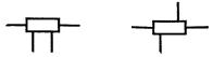
Resistors are distinguished by resistance and power. Resistance, as you already know, are measured in ohms, kiloohms and megoohms, and power- in watts. Resistors of different power differ in size. The greater the power of the resistor, the larger its size. Appearance fixed resistors is shown in Fig. 1. It also shows the conditional graphic designation of resistors on circuit diagram indicating power. More often, the power is indicated next to the resistor or they talk about it in the description of the circuit.
To miniaturize their devices, some use CHIP components, among which there can be both resistors and capacitors. On Fig. 1g shown appearance chip resistor. In foreign electronics, it is called smd(from Surface Mounted Device - a surface-mounted device). In other words Chip components are leadless radio components for mounting on the side of printed conductors.
Rated value resistor resistance is indicated by the manufacturer on the product case. A number of other characteristics are also applied there. For marking resistors, special encodings are used: alphanumeric, color and digital.
In alphanumeric marking, the unit of resistance Ohm is abbreviated as the letter E or R, kiloohm - letter To, megoom - letter M. If the nominal resistance of the resistor is expressed as an integer, then letter designation units of measurement are placed after this number, for example: ZZE (33 Ohm), 47K (47 kOhm), YuM (10 mOhm). When the resistance of the resistor is expressed as a decimal fraction less than one, then the letter designation of the unit of measure is placed in front of the number, for example: K22 (220 Ohm), M47 (470 kOhm). When expressing the resistance of the resistor as an integer with a decimal fraction, the integer is placed in front of the letter, and the decimal fraction after the letter, which symbolizes the unit of measurement (the letter replaces the comma after the integer), for example: 1E5 (1.5 Ohm), 2K2 (2.2 kOhm), 1M5 (1.5 mOhm). In addition, manufacturers also apply the allowable power to the resistor case. For example, MLT-1 means a 1 W resistor. As you guessed, this marking is correct for domestic resistors. In foreign countries, it is customary to use colors and numbers.
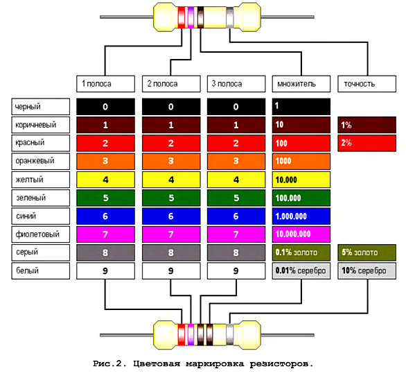
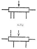
Color marking is applied to the cylindrical surface of the resistor in the form of dots or ring-belts.. Markings are placed on the resistor from left to right in the following order: first sign- the first digit; second character- the second; third- multiplier. These signs define the nominal resistance. The fourth sign is the permissible deviation of the resistance. For resistors with a nominal resistance expressed in three digits and a multiplier, the color marking consists of five characters(rings): the first three characters are three digits of the face value: the fourth character is the multiplier, the fifth is the permissible deviation of the resistance (see.Rice. 2). As a result, there are many online online calculators to determine the resistance of resistors. But, as for me, it is easier to find out the resistance of the resistor using a digital device - a tester.
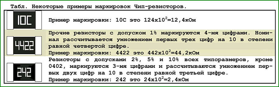
With digital labeling the resistance value of the resistor is applied three digits, of which the first two show its mantissa, and the third serves as an exponent of 10 for an additional factor. For example, 150 means 15 ohms, 151 means 150 ohms, 152 means 1500 ohms, etc. Accordingly, on a resistor with a resistance of 15 MΩ, we will see in this code: 156. Digital marking mainly used in SMD components. The following table shows examples of some digital markings.

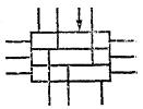
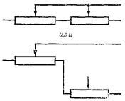
Earlier, I mentioned the power of resistors. In domestic electronics, the standards are tougher not only for resistors, but also for other components. This is clearly shown in Fig. 3. From here it follows: if the description of the circuit refers to the use of, for example, MLT-2, it must be replaced with a foreign resistor of greater power. Otherwise, your device will not last long.
Unlike fixed resistors, which have two outputs, variable resistors there are three such conclusions. Potentiometers can contain more than three outputs. Such variablesResistors are commonly used to compensate for frequencies in audio equipment.
![]()

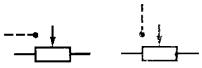
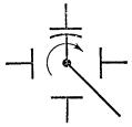
The diagram indicates the resistance between the extreme terminals of the replaceable resistor. The resistance between the middle terminal and the extreme ones changes with the rotation of the axis of the resistor, which protrudes outward. Moreover, if the axis is returned to one side, the resistance between the middle pin and one of the extreme ones increases, respectively, decreasing between the middle pin and the other extreme one. If the axis is returned back, the opposite happens. Variable resistors, like constant ones, can be of different power, which can be determined by their size. Wirewound resistors, which are designed to operate in DC and AC circuits, have especially high power. The appearance of some
variable resistors and their designation on the circuit diagram are shown in Fig. four.
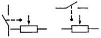
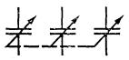
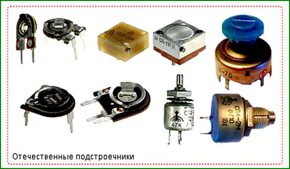
They work in a similar way trimmer resistors
, however, they, as the name already implies, serve to adjust, or rather, to set a more accurate resistance. After that they are no longer touched. The appearance of some trimmers and their designation on the circuit diagram are shown in Fig.5.

Resistors are noisy! Distinguish between intrinsic noise and slip noise. The inherent noise of resistors is the sum of thermal and current noise. Their occurrence is associated with the thermal motion of free electrons and the passage electric current. The inherent noise of the resistors is higher, the higher the temperature and voltage. High level resistor noise limits sensitivity electronic circuits and interferes with the reproduction of the useful signal. Slip (rotation) noise is inherent in variable resistors. They occur in a dynamic mode when a moving contact moves along a resistive element in the form of an interference voltage. In receiving devices, these interferences lead to various rustles and crackles. Therefore, electronics began to use digital
adjustment. Now it is not often in the equipment you will find a volume control built on a potentiometer.
In addition to the above resistors, there are semiconductor non-linear resistors- electronic products, the main property of which is the ability to change their electrical resistance under the influence of control factors: temperature, voltage, magnetic field and others. Depending on the influencing factor, they are called photoresistors, thermistors and varistors. Recently, they have been referred to as controlled semiconductor resistors. In other words, these are elements that are sensitive tothe influence of a certain control factor (see Fig. 6).
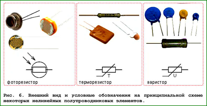
Among them - photoresistors, changing their resistance depending on the degree of illumination. The more intense the light, the more free charge carriers are created and the lower the resistance of the element becomes. Photoresistors also have a temperature range. If the sensor is used at different temperatures, then it is necessary to introduce refinement transformations, because resistance property depends on the outside temperature. Depending on the purpose, photoresistors have a completely different design. Sometimes it is just a semiconductor plate on a glass base with current-carrying leads, in other cases the photoresistor has a plastic case with rigid pins. Photoresistors are widely used in the printing industry to detect paper tape breaks, control the number of sheets fed into the printing machine. Can't do without them and circuit breakers street lighting.
Thermistors, or thermistors- change their resistance depending on the temperature. There are thermistors with both negative and positive temperature coefficient of resistance - thermistors.
Thermistors are used in systems for remote and centralized temperature measurement and control, fire alarms, thermal control and protection of machines, power measurement, vacuum measurement, liquid and gas velocities, etc. Nominal resistance RH - electrical resistance, the value of which is indicated on the thermistor or indicated in normative documentation, measured at a certain temperature environment(for most types of these resistors at 20 °C, and for thermistors with high operating temperatures up to 300 °C).
A distinctive feature of varistors is a pronounced relationship electrical resistance from the voltage applied to them. They are used
for stabilization and overvoltage protection, frequency and voltage conversion, as well as for gain control in automation systems, various measuring devices, in television receivers. For example, a varistor is often used in network (at 220V) extension cords. By connecting such a part in parallel with the extension cord outlets, the developers do not hesitate to announce a variety of different protections and filters.


