We construct the dependence of efficiency on the load. When β= 0, the useful power and efficiency are equal to zero. With an increase in the output power, the efficiency increases, since the specific value of magnetic losses in steel, which have a constant value, decreases. At a certain value (β opt), the efficiency curve reaches a maximum, after which it begins to decrease with increasing load. The reason for this is a strong increase in electrical losses in the windings, which increase in proportion to the square of the current.
Increasing the efficiency of transformers by a few percent would already be enough to keep the output of several factories. The problem is the energy wasted during this transformation. Even as a non-professional, this is realized when some kind of transformer household appliances begins to hum or heat up. But in the case of a general supply of electricity, the losses of giant transformers at conversion stations are much higher.
Neutron Interferometry Analysis Method
Before the development of neutron interferometry, researchers who wanted to study transformer magnets had to resort to the so-called Kerr microscopy. This method allows one to visualize the direction of magnetization on the surface of an iron core and derive domains using certain models. However, in order to be able to use it, it is necessary to remove the insulating coating from the iron core. However, this core is not made of an iron block, but of several superimposed ultra-thin sheets, each wrapped with a magnesium silicate insulating coating.

45. Under what condition is the efficiency of the transformer maximum?
The maximum efficiency in high power transformers reaches very high limits (0.98 ... 0.99).
β opt, at which the efficiency has a maximum value, can be determined by taking the first derivative dη/ dβ according to the formula and equating it to zero. efficiency has a maximum when the electrical losses in the windings are equal to the magnetic losses in the steel.
This phenomenon is related to another function of the coating: the induction of mechanical tension in the sheet, which improves the structure of the domains. In other words, when the coverage is removed, the configuration of the domains also changes. In fact, Kerr microscopy cannot provide an original image of real processes.
Frequency-induced bulk magnetic freezing of domain walls visualized by neutron dark field imaging. Proportional to their power and constant, regardless of their load. That is why it is important not to increase them too much. On the other hand, insufficient calibration is also harmful.
46. The optimal load factor at which the efficiency of the transformer is maximum. Formula.
47. What winding connection schemes are used in 3-phase transformers?
Three-phase transformers can be connected in star, star with zero point, delta or zigzag with zero point.
Transformers do not have maximum efficiency at full load, but at around 50% load. Abnormal heating of the windings appears with the opening of protections, shutdown of the installation and premature aging. In renewal, the task is easier than in new construction. Indeed, one can rely on the electric bills of yesteryear.
It can often be seen that the result of this formula results in a new power well below the existing transformer. The additional investment is not insignificant. Electrical transformer - Passive component - Electronic component - Power distribution - Electromagnetic device.
48. What is the peculiarity of the zigzag connection?

A feature of the "zigzag" scheme is that each phase of the winding is divided into two equal parts (half-phases), which are placed on different rods of the magnetic circuit and connected to each other in series and counter. The EMF of the phase of the winding connected in a "zigzag" is equal to the geometric difference in the EMF of the half-phases, which are shifted by 120 º. Therefore, to achieve equality of the phase EMF of the winding connected according to the "star" scheme and the winding connected according to the "zigzag" scheme, the number of turns of the latter must be increased by 2/(3) 1/2 ~ 1.15 times. This is a disadvantage of the "zigzag" scheme, since with such a connection the consumption of the winding wire increases.
Related page
An electrical transformer is a converter used to change the values of voltage and current supplied alternative source electricity, in device voltage and current different values, but with the same frequency and shape. It performs this conversion with excellent output. It is similar to a mechanical mechanism.
Static transformers and switches can be distinguished. In a static transformer, energy is transferred from the primary to the secondary through a magnetic circuit formed by the transformer body. These two circuits are then magnetically linked. This serves to provide galvanic isolation between the two circuits. In a switch, energy is transferred mechanically between a generator and an electric motor.
49. In which transformers is the zigzag winding connection used?
The primary and secondary windings of three-phase transformers can be connected according to the "star", "star with zero point", "triangle" or "zigzag with zero point" schemes.
Zigzag connection diagram
Sectional view of a three-phase transformer. Transformer installation. The primary windings or secondary windings may have external connections, known as connectors, at intermediate points in the winding to provide a choice of voltage ratio. Sockets can be connected to automatic device Tap changer for frequency distribution circuit. The audio frequency transformers used to distribute sound to loudspeakers have connectors that allow you to adjust the impedance of each of the loudspeakers.
cooling device
The medium voltage transformer is often used in audio power amplifiers. The modulation transformers in AM transmitters are especially identical. In the field of low voltage electricity and in the field of electronics, the heat dissipation of transformers is achieved by simple natural convection of air around the primary and secondary winding.
Each phase consists of 2 identical coils placed on different rods and interconnected in opposite directions so that the vectors of the EMF induced in them are subtracted.
50. Transformer connection group. Definition.
From lectures- GROUPS OF CONNECTIONS OF TRANSFORMER WINDINGS
Transformers are divided into groups depending on the phase shift between the linear voltages measured at the terminals of the same name.
In the case of high voltage and powerful electrical circuits transformers can be equipped various systems cooling. The cooling system is always connected to a temperature sensor device acting as a thermostat. The oil contained in the tank has a dual role: heat transfer and dielectric.
Operation of a single-phase transformer
Finally, in the field of high power broadcasting, impedance and tuning transformers sometimes consist of a huge rigid copper choke in which pure water circulates.
Ideal or Ideal Transformer
It is a virtual lossless transformer and is used to simulate real transformers which are recognized as an association of an ideal transformer and various impedances.single phase transformers. In them, the voltages of the primary and secondary windings can be in phase or be shifted by 180 o

Groups of compounds are denoted by integers from 0 before 11. The group number is determined by the angle value, by which the linear voltage vector of the LV winding lags behind the linear voltage vector of the HV winding. To determine the group number, this angle should be divided by 30°.
In the case when the combination of losses and leakages of the flux is neglected, the ratio of the number of primary turns to the number of secondary turns completely determines the transformation ratio of the transformer. Since losses are neglected, the power is transferred completely, so the current intensity in the secondary will be inversely, which is almost 19 times greater than in the primary.
Transformer power loss
On the equality of visible forces: either: one attracts. This is a set of autotransformers since it contains only one coil. The output branch of the secondary winding can be moved by a sliding contact on the turns of the primary winding. The isolation transformer is only intended to create electrical insulation between multiple circuits for safety reasons or to solve technical problems. The set of secondary isolated primary transformers shall be recognized as an isolation transformer; however, in practice the name is used to refer to transformers whose output voltage has the same effective value as the input voltage.
For single-phase transformers, only two groups of connections are possible: zero and sixth.
Depending on the connection scheme of the windings (U and D) and the order of connection of their beginnings and ends, different phase angles between linear voltages are obtained.


An isolation transformer has two windings, almost similar to the primary and secondary windings. The number of turns of the secondary winding is often especially slightly larger than the number of turns of the primary, to compensate for the low voltage drop during operation, the wire sections on the primary and secondary windings are similar in that the current intensity is the same. They are, for example, widely used in operating rooms: each room in the block is equipped with its own isolation transformer to avoid a fault in it causing failures in another room.
When connecting the LV winding according to the Z n scheme, and the HV winding according to the Y scheme phase voltages the LV windings are shifted relative to the corresponding phase voltages of the HV winding by an angle of 330 °, i.e. with such a connection we have the eleventh group. This is explained by the fact that there is the same angle between the linear voltage vectors.

A transformer is still an impedance transformer, but electronics gives this name to transformers that are not used in power circuits. An impedance transformer is essentially designed to adapt the output impedance of an amplifier to its load.
The transformer is then used not only to adapt the impedance and output level of the devices to the mixer's microphone inputs, but also to match the output of the connected devices. HF technology also uses transformers whose magnetic circuit is made of ferrite or without a magnetic circuit to adapt the output impedances of the amplifier, transmission line and antenna. Indeed, for optimal power transfer from the amplifier to the antenna, the speed of the standing waves must be equal. Measuring transformers are the interface between the electrical network and the measuring device.
From the Internet- Determination of the connection group of three-phase transformers
The transformer connection group characterizes the phase shift between the linear voltage vectors of the primary and secondary windings. The connection group is usually expressed as a number obtained by dividing by 30 the angle (in degrees) by which the secondary stress vector lags behind the corresponding primary stress vector.
Power available on a secondary basis is determined according to needs measuring device. Transformers are an integral part electrical network. Their reliability directly affects the reliability of the network. The failure of this critical device can affect the entire network and contribute to network instability. Since the replacement of a high voltage transformer requires a certain amount of organization for many reasons, such as drivers working time sometimes exceeding one year, it is recognized that the preparation for this equipment is beneficial to the proper functioning of the network.
When transforming electrical energy part of it is spent to cover losses, which are divided into electrical and magnetic. All losses are active.
Electrical losses due to the heating of the transformer windings when flowing through them electric current and are determined by the sum of electrical losses in the primary and secondary windings:
Proper control of a high voltage transformer requires information about the condition of the transformer. There are various components of a transformer that need to be inspected and evaluated to determine its overall condition, and several tests can provide this information. These tests include transformer insulation resistance, winding resistance, scan frequency response analysis, and load controls. On the Transformer Applications page.
Transformer testing equipment
The test to be performed differs depending on the life stage of the transformer, but should include at least routine screening. This brings us to the important issue of selecting transformer test equipment. Although test equipment can minimize the difficulty, testing and evaluating transformers remains challenging. Even with very accurate hardware, the results may not accurately represent the state of the device. The test of a transformer may be influenced by the preparation of this test, environment or checking its connecting conductors.
,
where is the number of phases in the transformer windings (usually 1 or 3); – losses short circuit at rated load.
Electrical losses are called variables, since they depend on the load current (proportional to the square).
Magnetic losses occur in the magnetic circuit of the transformer due to the presence of an alternating magnetic flux in it. This flow causes two types of losses in the magnetic circuit: losses from eddy currents in the steel of the magnetic circuit and losses from hysteresis (magnetization reversal) associated with the energy consumption for the destruction of residual magnetism in the ferromagnetic material of the magnetic circuit:
Standards organizations no longer provide a "correction factor" and recognize that each transformer changes in temperature and condition. This is one of the strengths of Megger. We don't just inform you about the differences in testing, we develop and integrate security mechanisms into our solutions.
We are constant innovators determined to move forward. Our conductor tests are made in such a way as to stay in place while sending current. Attention to detail, safety and ease of use are inherent in our products. Providing test equipment and solutions is our focus. Winning and maintaining your trust is our goal.
![]() .
.
Hysteresis losses are directly proportional to the remagnetization frequency (), and eddy current losses are proportional to its square (). The total magnetic losses are considered to be proportional to the frequency to the power of 1.3, i.e. . Since the current frequency is constant, and the magnitude of the magnetic flux at a load that does not exceed the rated one practically does not change, the magnetic losses are considered permanent, i.e. load independent. For this reason, the magnetic losses are almost equal to the no-load losses.
What are some solutions for dirty power?
In this section you will find a list of the most frequently asked questions. If you don't have an answer to your questions, please feel free to contact us using the form below. There are so many solutions that there are problems. We have summarized some solutions and their price range in the table below.
Unfiltered surge protectors are inexpensive and can provide protection against surges or other surges, but they do not filter out adverse noise. Better known as a surge suppressor. Surge suppression filters are inexpensive solutions for noise suppression and surge protection.
Transformer efficiency- the ratio of active power at the output of the secondary winding (useful power) to the active power at the input of the primary winding (power input):
 ,
,
where is the sum of losses.
Active power at the output of the secondary winding of the transformer:
,
where is the number of phases of the transformer; and - phase voltages and currents; – load power factor; – load factor.
Transformer Rated Power:
![]() .
.
In a three-phase transformer
,
where and are rated (linear) voltages and currents; and - rated phase voltages and currents.
Taking into account the dependence of active power at the output of the transformer and losses from the load, we obtain an expression for calculating the efficiency:
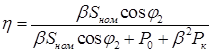 or
or  .
.
The efficiency of the transformer depends both on the magnitude of the load and on its nature (), see Figure 1.18. The maximum efficiency value corresponds to the load at which the magnetic losses are equal to the electrical (), whence

Rice. 1.18. Dependence of magnetic, electrical losses and efficiency on the relative secondary load current.
In modern power transformers  and the maximum efficiency value corresponds to the load
 ![]() .
.
Autotransformers
autotransformer- this is a transformer in which, in addition to magnetic, there is an electrical connection between the primary and secondary windings. Prefix " auto" (Greek " myself"") means that in an autotransformer part of the winding acts both as the primary and as the secondary winding of the transformer.
Figure 1.19 shows an autotransformer circuit for switching on a transformer designed to transfer electrical energy from an input network with voltage U into the output network with voltage .

Rice. 1.19. Schematic diagrams single-phase and three-phase step-up autotransformer, the dependence of power values and on the transformation ratio.
The circuit uses a two-winding transformer with windings 1 and 2 located on the same rod. For visualization of winding 1 and 2 are shown at different sections of the rod in height. Primary winding transformer 1 switches to low voltage network voltage U. The secondary winding is connected between the clamp a(X) input network and clamp X output network so that its voltage is added to the voltage U and increased it to voltage.
The secondary winding of an autotransformer is in electrical contact with the input and output networks, unlike a conventional transformer. Therefore, the insulation of the secondary winding must be designed for the largest of the voltages and (in the circuit for increasing the voltage according to Figure 1.19 - for voltage), and not for voltage, as in a conventional transformer.
Autotransformer transformation ratio:
 ,
,
where 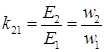 .
.
The description of electromagnetic processes in the autotransformer circuit includes the transformer equations (on the left) and the equations that describe the autotransformer circuit (on the right).
 ; ;
| ;
|
The total power of an autotransformer, excluding losses, can be represented as two components.


