They appear in the presence of an external periodically changing force. Such oscillations appear, for example, in the presence of a periodic electromotive force in the circuit. A variable induction emf occurs in a wire frame of several turns, rotating in the field of a permanent magnet.
In this case, the magnetic flux penetrating the frame changes periodically. In accordance with the law of electromagnetic induction, the emerging EMF of induction also periodically changes. If the frame is closed to a galvanometer, its arrow will begin to oscillate around the equilibrium position, indicating that an alternating current is flowing in the circuit. A distinctive feature of forced oscillations is the dependence of their amplitude on the frequency of changes in the external force.
Alternating current.
Alternating current is an electric current that changes with time.
Alternating current is different kinds impulse, pulsating, periodic and quasi-periodic currents. In engineering, alternating current usually means periodic or almost periodic currents of an alternating direction.
The principle of operation of the alternator.
The most commonly used periodic current, the strength of which varies over time according to harmonic law(harmonic, or sinusoidal alternating current). This is the current used in factories and factories and in the lighting network of apartments. It is a forced electromagnetic oscillation. Industrial frequency alternating current is 50 Hz. AC voltage in the sockets of the lighting network sockets is created by generators at power plants. The simplest model such a generator is a wire frame rotating in a uniform magnetic field.
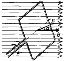
Flux of magnetic induction F, penetrating a wire frame with an area S, proportional to the cosine of the angle α between the normal to the frame and the magnetic induction vector:
Ф = BS cos α.
With uniform rotation of the frame, the angle α increases in proportion to time t: α = 2πnt, where n- rotation frequency. Therefore, the flux of magnetic induction changes harmonically with the cyclic oscillation frequency ω = 2πn:
Ф = BS cos ωt.
According to the law of electromagnetic induction, the induction emf in the frame is:
e \u003d -Ф "\u003d -BS (cos ωt)" \u003d ɛ m sin ωt,
where ɛm= BSω is the amplitude of the induction emf.
Thus, the voltage in the AC network changes according to a sinusoidal (or cosine) law:
u = Um sin ωt(or u = U m cos ωt),
where u- instantaneous voltage value, U m- voltage amplitude.
The current in the circuit will change at the same frequency as the voltage, but a phase shift is possible between them. φ with. Therefore, in general case instantaneous current value i is determined by the formula:
i = I m sin(φt + φWith) ,
where I m is the amplitude of the current.
The strength of the current in an alternating current circuit with a resistor. If a electrical circuit consists of active resistance R and wires with negligible inductance
Lecture6 . Electromagnetic oscillations and waves.
Lecture plan
Free undamped oscillations in an oscillatory circuit.
Free damped electromagnetic oscillations.
Forced electromagnetic oscillations. electrical resonance.
Electromagnetic waves.
1. Free undamped oscillations in the oscillatory circuit.
Among electrical phenomena, a special place is occupied by electromagnetic oscillations, in which electrical quantities (charges, currents, electric and magnetic fields) change periodically. To excite and maintain electromagnetic oscillations, certain systems are required, the simplest of which is an oscillatory circuit.
Oscillatory circuit A circuit consisting of a coil of inductance L and a capacitor of capacitance C connected in series.
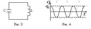
Let's consider the process of occurrence of electromagnetic oscillations in an idealized oscillatory circuit, in which the resistance of the connecting wires can be neglected. For excitation in the oscillation circuit, the capacitor is preliminarily charged, giving its plates a charge q 0 from an external source (Fig. 1).
In a charged oscillatory circuit, free oscillations are established, called electromagnetic. In this case, the values of all electrical and magnetic quantities fluctuate.
Electromagnetic oscillations occur in the circuit, during which the energy of the electric field is converted into energy magnetic field and vice versa. Figure 2 is a graph of the charge of a capacitor  from time
  ,
, , on which the charge values at the instants of time
  the corresponding states of the oscillatory circuit are compared (a; b; c; d; e).
 Electromagnetic oscillations are in many ways similar to mechanical oscillations, i.e. the equations describing them and their solutions are similar.
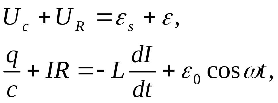
Let's write for the circuit the 2nd Kirchhoff rule for an arbitrary moment of time: the sum of the voltage drops is equal to the sum of the emfs acting in the circuit. Only one emf acts in the circuit - self-induction emf  , and the voltage drop occurs across the capacitor, so
where  - instantaneous value of the charge on the capacitor plates.


Denote 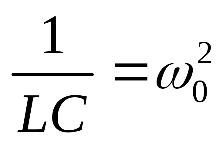 ;
;
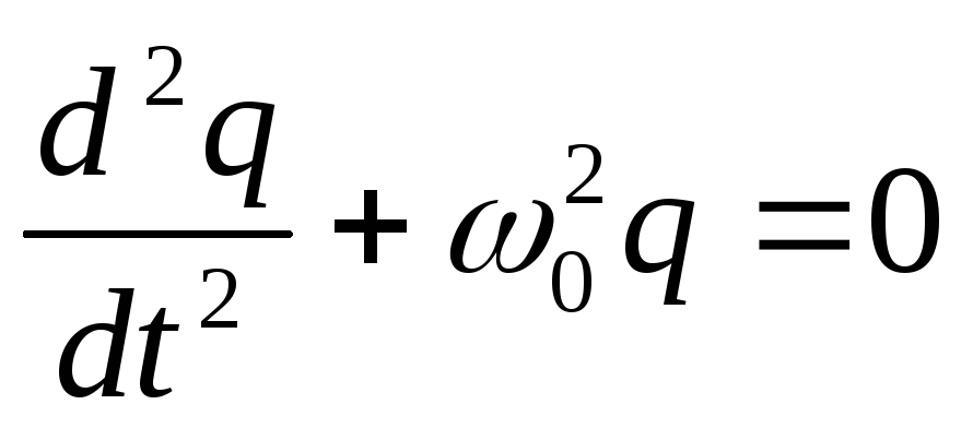 -differential equation of free electromagnetic oscillations.
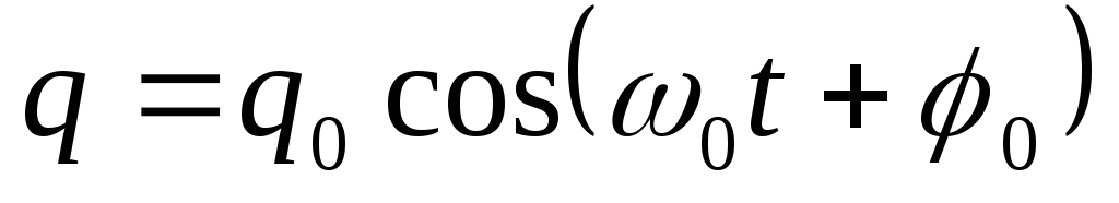 .
.
Thus, in an ideal oscillatory circuit (Fig. 3), charge oscillations occur according to a harmonic law (Fig. 4).
 ,
,
those. current fluctuations lead charge fluctuations in phase by when the current reaches its maximum value, the charge and voltage turn to zero (and vice versa).
Because natural cyclic frequency of the circuit,
![]() Thomson formula.
Thomson formula.
Free damped electromagnetic oscillations.
Because every conductor has resistance; during the passage of current in the oscillatory circuit, Joule heat is released, i.e. energy is lost, therefore free electromagnetic oscillations in a real circuit (Fig. 5) are always damped. For such a circuit
 , where
 ![]() - voltage drop across the active resistance of the circuit.
- voltage drop across the active resistance of the circuit.
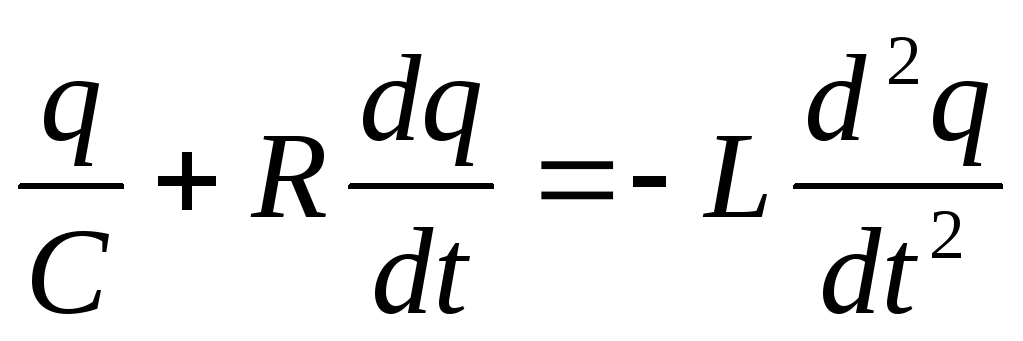 or
or 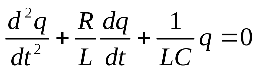 .
.
Denote 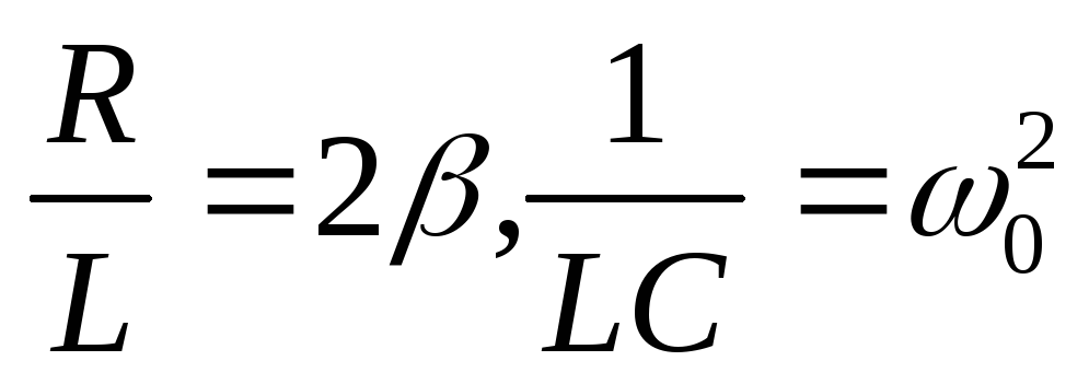 .
.
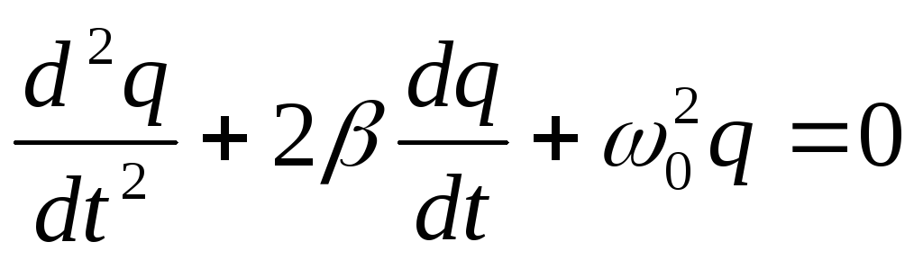 -differential equation of free damped electromagnetic oscillations.
The solution to this equation is the expression  .
.
cyclic frequency of natural undamped oscillations;
![]() cyclic frequency of natural damped oscillations;
cyclic frequency of natural damped oscillations;
the law of decreasing amplitude (Fig. 6), where  - amplitude at t=0.

Find out the physical meaning of . We introduce the concept reaction time- time for which the amplitude decreases in e times.
Thus, is the reciprocal of .
Logarithmic decrement per swell - the natural logarithm of the ratio of 2 amplitudes that differ in time by a period.
In time , the system will oscillate.
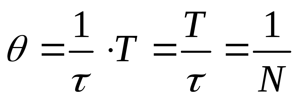 ,
,
 is the number of oscillations for which the amplitude decreases by a factor of e.
The quality factor characterizes the ability of the oscillatory circuit to damp oscillations:
Q 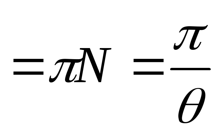 .
.
The quality factor is proportional to the number of oscillations during which the amplitude decreases by a factor of e.
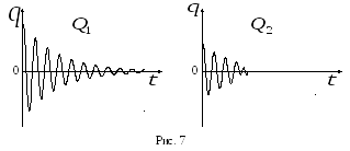
If Q is large, the oscillations decay slowly (Fig. 7,  ).
).
Forced electromagnetic oscillations. electrical resonance.
Free electromagnetic oscillations occur with a frequency determined by the parameters of the circuit  ,
, and
and  , and in a real oscillatory circuit decay with time due to energy losses. To obtain undamped oscillations, energy losses must be compensated. Thus, to obtain undamped electromagnetic oscillations, it is necessary to introduce an emf into the circuit, periodically changing over time according to the harmonic law:
 ,
,
where 0 is the emf amplitude; is the cyclic frequency of the driving emf.
compelled called electromagnetic oscillations that occur under the action of a periodically changing emf (Fig. 8).
because 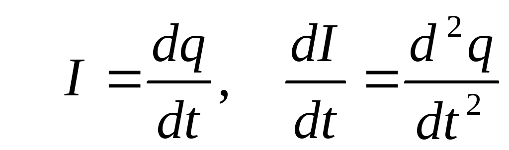 ,
,
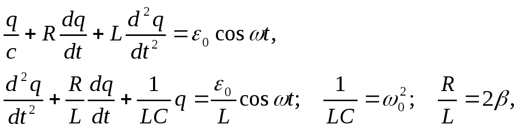
 -differential equation of forced electromagnetic oscillations.
It can be proved that the solution to this equation is the expression:
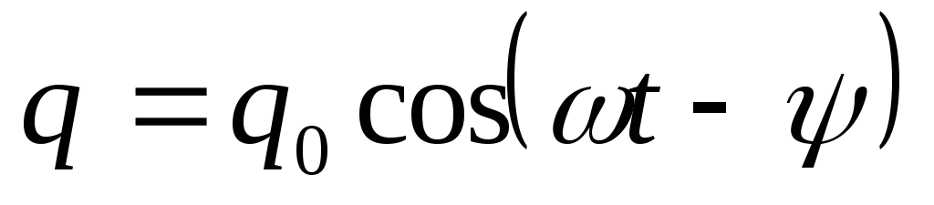 .
.
H  and fig. 9 shows a graph of the dependence of the capacitor charge on time in the case of steady state forced electromagnetic oscillations.
Forced vibrations are made with the same frequency  , which is the forcing e.m.f. It has been experimentally established that the change lags behind in its change from changes in emf
  ;y- phase difference of oscillations and , phase shift between change and .
Peak value charge and  are defined by the formulas:
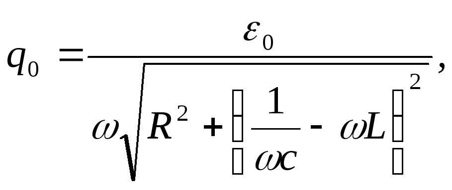
![]() .
.
Because  one can find w for which
  .
.
Calculations show that  .
.
E 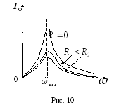 electrical resonance- the phenomenon of a sharp increase in the amplitude of forced oscillations, when the frequency of the driving emf approaches the natural frequency of the oscillatory circuit
  .
.
How more resistance contour R, the more flattened is the resonance curve (Fig. 10).
Electromagnetic waves.
An electric charge moving uniformly in vacuum (relative to ISO) does not radiate. This is obvious from the principle of relativity, according to which all ISOs are equal. In a system moving together with a charge, it is stationary, and stationary charges do not radiate. The charge field (electrostatic in his own system and electromagnetic in all others) moves with him. If the charge moves with acceleration under the action of external forces, the field, which has energy, and therefore mass and inertia, is, as it were, separated from the charge and radiated into space at the speed of light. Radiation occurs as long as an external force acts on the charge, imparting acceleration to it. Example: synchrotron radiation, at energies 10 7 eV, electrons emit visible light, at 10 9 eV - x-rays.
The movement of a charge with acceleration changes electric field near him. This alternating electric field, according to Maxwell's theory, generates a magnetic field interconnected with it in the surrounding space, which, in turn, being variable, generates a vortex electric field in neighboring areas of space, as a result of which the process propagates in space in all directions with great speed (Fig. 11).
Thus, if an electric charge moves with acceleration (or oscillates), in the surrounding space, capturing ever larger areas, a system of mutually perpendicular, periodically changing electric and magnetic fields arises. An electromagnetic wave is formed, running in all directions from an oscillating charge.
P 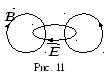 The process of propagation of electromagnetic oscillations in space is called electromagnetic wave. The main condition for EMW radiation is the presence of acceleration.
The vectors are perpendicular to each other and to the direction of propagation and form a right-handed system with it. Because the ![]() EMW is transverse (Fig. 12). At distances from the source that are much greater than the wavelength, the EMW is flat.
EMW is transverse (Fig. 12). At distances from the source that are much greater than the wavelength, the EMW is flat.
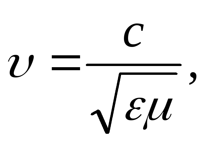 where
where 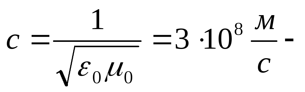 EMW speed in vacuum,
 .
.
We obtain the equation of a plane EMW (Fig. 13).

If at the point O , at the point M
 ;
;
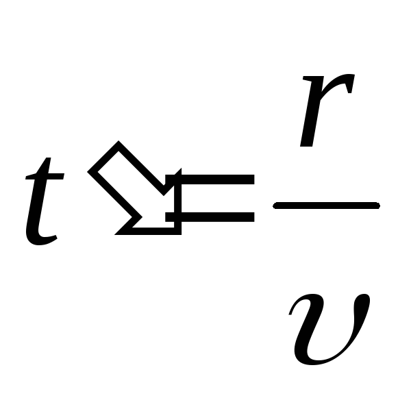 is the time it takes the wave to travel the distance
  from the point
  to the point
  .
.
Because 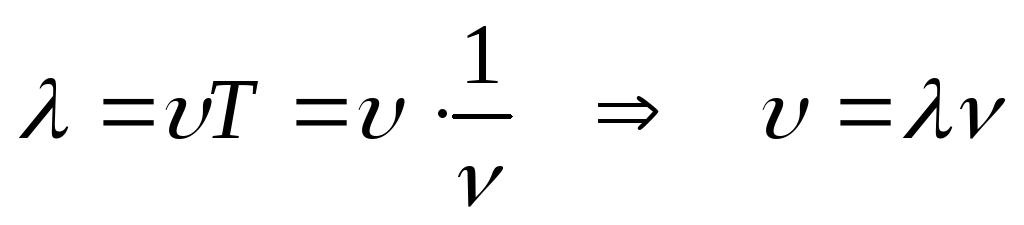 ,
,
where is the wave vector.
In general ,.
The electromagnetic radiation field was discovered relatively recently, about 100 years ago. Over the past century, this discovery has led to significant changes in the life of society. Most radio engineering systems are based on the direct use of the electromagnetic field, i.e. radio waves for transmitting information (communications, broadcasting, television) or extracting it (radar, radio telemetry, etc.); The word "radio" actually means radiation.
There is no such area of human activity where radio engineering would not be applied or could not be applied. The progress of society without radio engineering, radio electronics is simply impossible. Radio electronics is used in various scientific research, space research, aviation, navy, medicine, metrology, geology, industry, agriculture. Recently, studies have been carried out on the possibility of transmitting solar energy from space photocells to the Earth using radio waves concentrated into narrow beams. Radio waves are widely used in military affairs: radar - to combat self-guided missiles; for airborne radar reconnaissance, etc.
Recently, it has become possible to obtain high-quality radar images of the earth's surface and objects, comparable in detail with aerial photographs.
The possibility of using radio signals to determine the location of reflecting objects (ships, aircraft, cars) was expressed by A.S. Popov, to whom the world owes the invention of the radio.
On the basis of radio direction finding systems, “autopilots”, systems for “blind” landing of aircraft in fog, and many other devices have been built.
Forced oscillations are called such oscillations that are caused by the action on the system of external forces that periodically change over time. In the case of electromagnetic oscillations, such an external force is a periodically changing emf. current source.
Distinctive features forced oscillations: forced oscillations - undamped oscillations; the frequency of forced oscillations is equal to the frequency of the external periodic action on the oscillatory system, i.e., in this case, it is equal to the frequency of the emf change. current source.
The amplitude of forced oscillations depends on the frequency of emf change. current source. Forced oscillations are characterized by the phenomenon of electrical resonance, in which the amplitude of forced oscillations becomes maximum. This physical phenomenon is observed when the frequency of emf change coincides. a current source with a natural oscillation frequency of a given circuit, i.e.:
where: i is the instantaneous value of the current, i.e. its value at time t = 0;
J0 - amplitude or maximum value of the current strength;
w - frequency of current change, numerically equal to the frequency emf changes current source.
In practice, it is inconvenient to use instantaneous or amplitude values of current and voltage. Ammeters and voltmeters in the AC circuit measure the so-called effective or effective values of the alternating current, which are related to the amplitude values of the current by the formulas:
The effective values of the current strength and voltage of the alternating current are the values \u200b\u200bof these quantities for such direct current, which, on the same active resistance, releases for a time equal to the period T of the alternating current, the same amount of heat as the given alternating current.
The source of alternating current is an alternating current generator, the physical principle of which is based on uniform rotation at an angular velocity w of a flat frame with area S, consisting of N turns, in a uniform magnetic field with induction B. In this case, the frame is pierced by an alternating magnetic flux:
where: Ф0 - the maximum value of the magnetic flux;
a is the angle between the normal to the frame and the magnetic induction vector B;
According to the law of electromagnetic induction, the instantaneous emf value will be excited in the frame, changing according to the law:
where: e - instantaneous emf value;
e0 - amplitude value of emf;
w is the angular velocity of the frame rotation.
In general, an alternating current circuit is an oscillatory circuit:

The voltage at the terminals of the current source U varies according to the harmonic law with the frequency of change of the emf. alternator.
There is a fundamental difference between the electrical resistance of the AC circuit compared to the electrical resistance of the DC circuit, associated with transformations electrical energy into other forms of energy.
Devices in which electrical energy is completely and irreversibly converted into other types of energy are called active loads, and electrical resistances these devices - active resistances. In a DC circuit, there are only resistive loads.
Devices in which there is no irreversible conversion of electrical energy into other forms of energy are called reactive loads, and their resistances are called reactive resistances. Reactances in an AC circuit have a capacitor and an inductor, which are respectively called capacitive reactance xc and inductive reactance xL. In this case, the capacitor has only reactance, and the inductor, in addition to reactance, also has active resistance. Reactances are calculated by the formulas:
where: C is the capacitance of the capacitor;
L is the inductance of the coil;
w is the frequency of emf change. current source.
If there is no reactive load in the alternating current circuit or its resistance is negligible compared to the active resistance of the circuit, then the current fluctuations coincide in phase with the voltage fluctuations and occur with the frequency and phase of the emf oscillations. current source:
An AC circuit that does not contain a capacitor and whose active resistance is negligible compared to inductive reactance is called an AC circuit with inductive resistance. In such a circuit, the voltage fluctuations on the coil are ahead of the current fluctuations by π/2, i.e.:
![]() . (14)
. (14)
AC circuit that does not have inductive reactance and the active resistance of which is negligible compared to the capacitance, is called an alternating current circuit with capacitance. In such a circuit, current fluctuations lead voltage fluctuations by π/2:
![]() . (21)
. (21)
Power is called active power. The factor cosφ is called the power factor, where: j is the phase shift between current and voltage fluctuations. The power factor is calculated by the formula.
Recall that it is convenient to observe oscillations in an oscillatory circuit. We call the oscillatory circuit the simplest system in which these oscillations can exist. The oscillatory circuit consists of two elements - a coil, with a certain number of turns, which has an inductance, and a capacitor, main characteristic which is the electrical capacity (Fig. 1).
Rice. 1. Coil and capacitor designations ()
Elements can be connected in different ways, but most often, in order to observe vibrations, they are connected, as shown in Fig. 2.
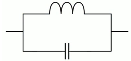
Rice. 2. Oscillatory circuit LC ()
A capacitor is connected in parallel to the coil, such a circuit is called an LC oscillatory circuit, thereby emphasizing that the circuit includes a capacitor and an inductor. This is the simplest system in which electromagnetic oscillations occur. As we already know, fluctuations can occur if there are certain conditions:
1. The presence of an oscillatory circuit.
2. The electrical resistance must be very small.
3. Charged capacitor.
This is all about free vibrations.
In order for undamped oscillations to arise - forced oscillations, we will each time have to impart additional energy to the capacitor in the oscillatory circuit. Let's see how it looks on the diagram (Fig. 3).
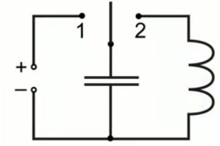
Rice. 3. Oscillatory circuit of forced electromagnetic oscillations ()
In this case, an oscillatory circuit is shown, the capacitor of which is equipped with a key. The key can switch to position 1 or position 2. When connected to position 1, the capacitor is connected to a voltage source and receives a charge, that is, the capacitor is charged. When connected to position 2, oscillations begin in this oscillatory circuit, the graph of this oscillatory circuit will look like this (Fig. 4).
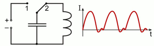
Rice. 4. Graph of forced electromagnetic oscillations ()
When the key is connected to position 2, the electric current increases, changes its direction and goes to attenuation, when the key is switched to position 1 and then to position 2, the next period of oscillation occurs. As a result, we observe a picture of forced electromagnetic oscillations occurring in the circuit.
The most common type of forced electromagnetic oscillations is a frame rotating in a magnetic field. This device is called an alternator, and the alternating current itself is forced electromagnetic oscillations.
In order to obtain undamped oscillations in the circuit, it is necessary to make a circuit in which the capacitor would be charged each time, at least one period.
When flowing electric current in the oscillatory circuit, each time there are energy losses that are associated with active resistance, that is, energy is spent on heating the wires, but there are two more important moments energy loss:
Energy costs for the action of the electromagnetic charge of the capacitor on the dielectric, which is located between the plates. The dielectric is affected electric field, which occurs inside the capacitor, in which case part of the energy is consumed;
When an electric current flows through the circuit, a magnetic field is created, which dissipates a certain amount of energy in the surrounding space.
To compensate for these losses, we must each time inform the capacitor of energy.
This problem was successfully solved in 1913, when a three-electrode electric lamp(Fig. 5).

Rice. 5. Three-electrode vacuum tube ()
Forced electromagnetic oscillations- periodic changes in current and voltage in the electrical circuit.
An electrical circuit is not necessarily an oscillatory circuit, but periodic changes in characteristics (current, voltage, charge), these will be forced electromagnetic oscillations.
Forced electromagnetic oscillations - undamped electromagnetic oscillations, since they do not stop for an arbitrarily long time, any time that we have planned.
The theory of the electromagnetic field was formulated by the English scientist James Maxwell, we will consider it in future lessons.
Bibliography
- Tikhomirova S.A., Yavorsky B.M. Physics ( a basic level of) - M.: Mnemozina, 2012.
- Gendenstein L.E., Dick Yu.I. Physics grade 10. - M.: Mnemosyne, 2014.
- Kikoin I.K., Kikoin A.K. Physics-9. - M.: Enlightenment, 1990.
Homework
- Define forced electromagnetic oscillations.
- What is the simplest oscillating circuit made of?
- What is necessary for the oscillations to be undamped?
- Internet portal Sfiz.ru ().
- Internet portal Eduspb.com ().
- Internet portal Naexamen.ru ().
Forced oscillations are called such oscillations that are caused by the action on the system of external forces that periodically change over time. In the case of electromagnetic oscillations, such an external force is a periodically changing emf. current source.
Distinctive features of forced oscillations: forced oscillations - undamped oscillations; the frequency of forced oscillations is equal to the frequency of the external periodic action on the oscillatory system, i.e., in this case, it is equal to the frequency of the emf change. current source.
The amplitude of forced oscillations depends on the frequency of emf change. current source. Forced oscillations are characterized by the phenomenon of electrical resonance, in which the amplitude of forced oscillations becomes maximum. This physical phenomenon is observed when the frequency of emf change coincides. a current source with a natural oscillation frequency of a given circuit, i.e.:
where: i is the instantaneous value of the current, i.e. its value at time t = 0;
J 0 - amplitude or maximum value of the current strength;
w is the frequency of current change, numerically equal to the frequency of change of emf. current source.
In practice, it is inconvenient to use instantaneous or amplitude values of current and voltage. Ammeters and voltmeters in the AC circuit measure the so-called effective or effective values of the alternating current, which are related to the amplitude values of the current by the formulas:
The effective values of the current strength and voltage of the alternating current are the values \u200b\u200bof these quantities for such a direct current, which, on the same active resistance, releases the same amount of heat in a time equal to the period T of the alternating current as the given alternating current.
The source of alternating current is an alternating current generator, the physical principle of which is based on uniform rotation at an angular velocity w of a flat frame with area S, consisting of N turns, in a uniform magnetic field with induction B. In this case, the frame is pierced by an alternating magnetic flux:
where: Ф 0 - the maximum value of the magnetic flux;
a is the angle between the normal to the frame and the magnetic induction vector B;
According to the law of electromagnetic induction, the instantaneous emf value will be excited in the frame, changing according to the law:
where: e - instantaneous emf value;
e 0 - amplitude value of emf;
w is the angular velocity of the frame rotation.
In general, an alternating current circuit is an oscillatory circuit:

The voltage at the terminals of the current source U varies according to the harmonic law with the frequency of change of the emf. alternator.
There is a fundamental difference between the electrical resistance of an AC circuit compared to the electrical resistance of a DC circuit, associated with the conversion of electrical energy into other types of energy.
Devices in which electrical energy is completely and irreversibly converted into other types of energy are called active loads, and the electrical resistances of these devices are called active resistances. In a DC circuit, there are only resistive loads.
Devices in which there is no irreversible conversion of electrical energy into other forms of energy are called reactive loads, and their resistances are called reactive resistances. Reactances in an alternating current circuit have a capacitor and an inductor, which are respectively called capacitive x c resistance and inductive reactance x L . In this case, the capacitor has only reactance, and the inductor, in addition to reactance, also has active resistance. Reactances are calculated by the formulas:
where: C is the capacitance of the capacitor;
L is the inductance of the coil;
w is the frequency of emf change. current source.
If there is no reactive load in the alternating current circuit or its resistance is negligible compared to the active resistance of the circuit, then the current fluctuations coincide in phase with the voltage fluctuations and occur with the frequency and phase of the emf oscillations. current source:
An AC circuit that does not contain a capacitor and whose active resistance is negligible compared to inductive reactance is called an AC circuit with inductive resistance. In such a circuit, the voltage fluctuations on the coil are ahead of the current fluctuations by /2, i.e.:
![]()
. (14)
An AC circuit that has no inductive reactance and whose active resistance is negligible compared to capacitive reactance is called a capacitive AC circuit. In such a circuit, current fluctuations lead voltage fluctuations by /2:
For the amplitude and effective values of the alternating current, Ohm's law is valid:
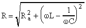
, (19)
where the value of R is called the impedance of the AC circuit.
The amount of heat Q released on the active resistance is calculated according to the Joule-Lenz law:
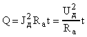
. (20)
The amount of converted electrical energy into other types of energy is determined by the power of the alternating current. Since the current and voltage are variables, the power in the alternating current circuit is also a variable. Therefore, it makes sense to talk only about the instantaneous value of power \u003d I 2 R a, or about the average value of the power during the period T of the change in alternating current, calculated by the formula:
![]()
. (21)
Power is called active power. The factor cosφ is called the power factor, where: j is the phase shift between current and voltage fluctuations. The power factor is calculated using the formula:
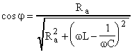
. (22)
A device called a transformer is used to convert alternating current of one voltage into alternating current of another voltage at the same frequency. The transformer is a system consisting of two windings (coils) connected by one core. If the original coil contains N 1 turns, and the secondary coil contains N 2 turns, then the transformation ratio k is calculated by the formula:
where e 1 and e 2 - e.m.f. induction in the primary and secondary windings.
If the voltage drop across the active resistance of the primary winding of the transformer is negligible, then: ε 1 = u 1 and ε 2 = u 2. Then:
efficiency transformer is called the ratio of power R 2 given by the secondary winding to the power R 1 supplied to primary winding:
![]()
. (25)
efficiency modern transformers is very high - 97-98%. Therefore, according to the law of conservation of energy, the current power in the primary winding is almost equal to the current power in secondary winding: R 1 R 2 . It follows that: J 1 U 1 J 2 U 2 .
Then formula (24) can be written as:
![]()
, (26)
where: J 1 , J 01 - effective and amplitude values of the current in the primary winding;
J 2 , J 02 - effective and amplitude values of the current in the secondary winding.
We advise you to read
 Psychological characteristics of children in adolescence
 Transferring a child to another school - the procedure and necessary documents Whether to transfer a child to another school
, diagnosis, treatment Treatment of urogenital chlamydia") Chlamydia urogenital - description, causes, symptoms (signs), diagnosis, treatment Treatment of urogenital chlamydia
Chlamydia urogenital - description, causes, symptoms (signs), diagnosis, treatment Treatment of urogenital chlamydia The benefits and significance of hydroamino acid threonine for the human body L threonine what

