There is another way to reduce the voltage on the load, but only for circuits direct current. See about here.
Instead of an additional resistor, a chain of diodes connected in series in the forward direction is used.
The whole point is that when current flows through the diode, “ forward voltage» equal, depending on the type of diode, power and current flowing through it - from 0.5 to 1.2 Volts.
On the germanium diode, the voltage drops 0.5 - 0.7 V, on the silicon diode from 0.6 to 1.2 Volts. Based on how many volts you need to lower the voltage at the load, turn on the appropriate number of diodes.
To lower the voltage by 6 V, you must approximately turn on: 6 V: 1.0 \u003d 6 pieces of silicon diodes, 6 V: 0.6 \u003d 10 pieces of germanium diodes. Silicon diodes are the most popular and available.
The above circuit with diodes is more cumbersome in execution than with a simple resistor. But, the output voltage, in a circuit with diodes, is more stable and weakly dependent on the load. What is the difference between these two methods of reducing the output voltage?
In Fig 1 - additional resistance - resistor (wire resistance), Fig 2 - additional resistance - diode.
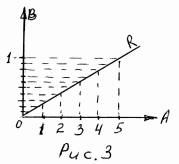
A resistor (wire resistance) has a linear relationship between the current passing through it and the voltage drop across it. By how many times the current increases, the voltage drop across the resistor will increase by the same amount.
From example 1: if we connect another one in parallel to the light bulb, then the current in the circuit will increase, taking into account the total resistance of the two light bulbs up to 0.66 A. The voltage drop across the additional resistor will be: 12 Ohm * 0.66 A = 7.92 V The bulbs will remain: 12 V - 7.92 V = 4.08 V. They will burn to the floor of the glow.
A completely different picture will be if instead of a resistor there is a chain of diodes.
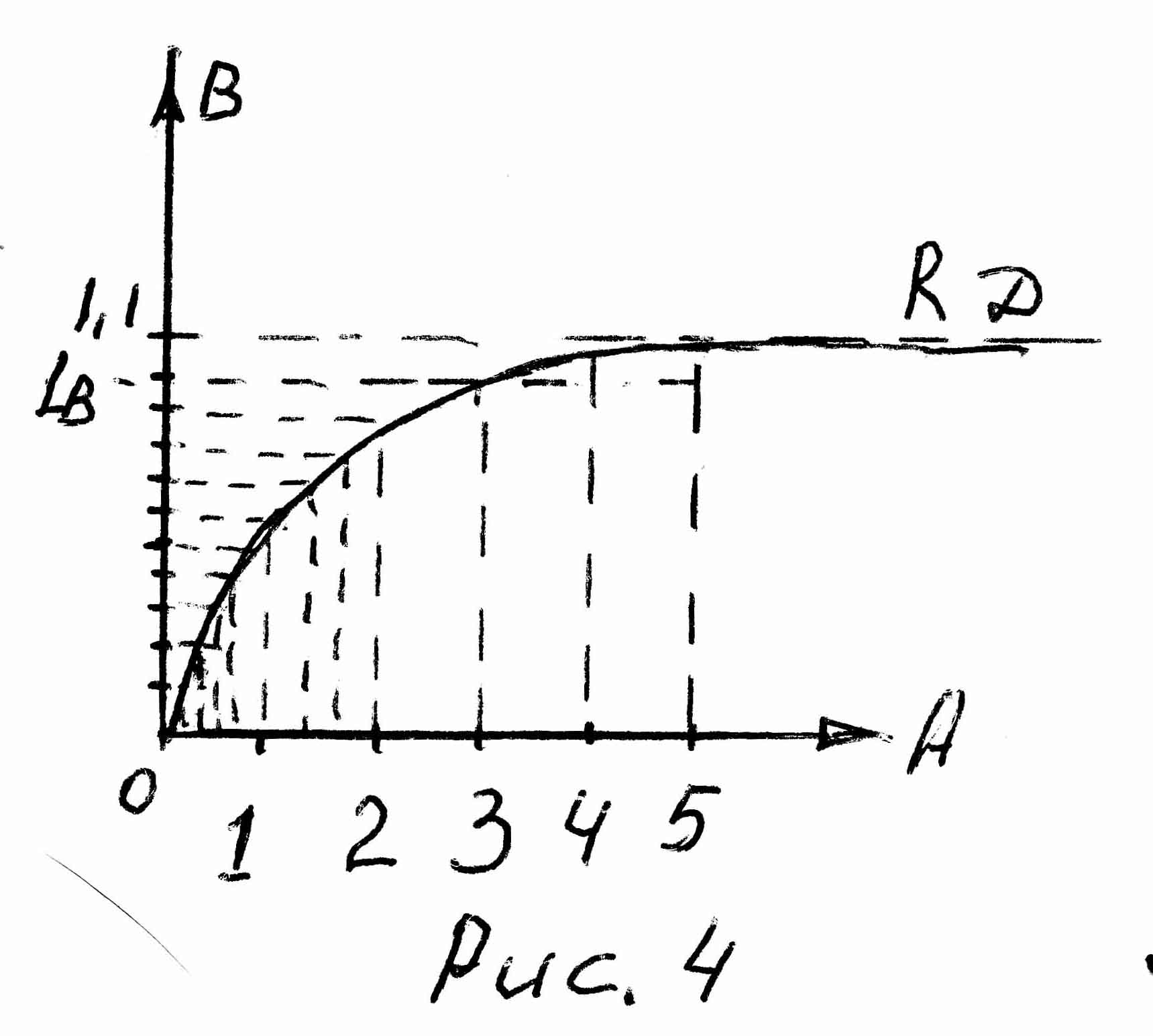
The relationship between the current flowing through a diode and the voltage drop across it is non-linear. The current can increase several times, the voltage drop across the diode will increase by only a few tenths of a volt.
Those. the greater the current of the diode, the less (compared with the resistor) its resistance increases. The voltage drop across the diodes is little dependent on the current in the circuit.
Diodes in such a circuit act as a voltage stabilizer. Diodes must be selected according to the maximum current in the circuit. Maximum admissible current diodes must be greater than the current in the calculated circuit.
The voltage drops on some diodes at a current of 0.5 A are given in the table. 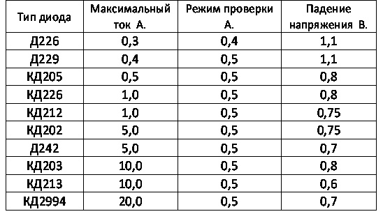
In chains alternating current, as an additional resistance, you can use a capacitor, inductance, dinistor or thyristor (with the addition of a control circuit).
For a person who is familiar with electrical equipment at the level of a simple user (knows where and how to turn it on / off), many of the terms used by electricians seem to be some kind of nonsense. For example, what does “voltage drop” or “circuit assembly” cost. Where and what falls? Who took the circuit apart? In fact, the physical meaning of the ongoing processes, hidden behind most of these words, is quite understandable even with school knowledge of physics.
To explain what a voltage drop is, it is necessary to remember what kind of voltages are in general (meaning the global classification). There are only two types of them. The first is the voltage that is connected to the circuit in question. It may also be referred to as applied to the entire chain. And the second type is precisely the voltage drop. It can be considered both in relation to the entire contour, and to any individual element.
In practice, it looks like this. For example, if you take the usual one, screw it into a cartridge, and connect the wires from it to a home power outlet, then the voltage applied to the circuit (power source - conductors - load) will be 220 volts. But as soon as we use a voltmeter to measure its value on the lamp, it becomes obvious that it is slightly less than 220. This happened because there was a voltage drop across which the lamp has.
Perhaps there is no person who has not heard of Ohm's law. AT general case its wording looks like this:
where R is the active resistance of the circuit or its element, measured in ohms; U - electrical voltage, in Volts; and finally I is the current in amperes. As can be seen, all three quantities are directly related to each other. Therefore, knowing any two, it is quite easy to calculate the third. Of course, in each specific case, you will have to take into account the type of current (AC or DC) and some other clarifying characteristics, but the basis is the above formula.
Electrical energy is, in fact, the movement of negatively charged particles (electrons) along a conductor. In our example, the filament of the lamp has a high resistance, that is, it slows down moving electrons. Due to this, a visible glow occurs, but the total energy of the particle flow is reduced. As can be seen from the formula, as the current decreases, the voltage also decreases. That is why the results of measurements at the outlet and on the lamp are different. This difference is the voltage drop. This value is always taken into account to prevent too much reduction on the elements at the end of the circuit.
The voltage drop across a resistor depends on the resistor and the current flowing through it. Temperature and current characteristics also have an indirect effect. If an ammeter is included in the circuit under consideration, then the drop can be determined by multiplying the current value by the resistance of the lamp.
But it is far from always possible that it is so simple with the help of the simplest formula and measuring device perform a voltage drop calculation. In the case of resistors connected in parallel, finding the value becomes more complicated. We have to additionally take into account the reactive component.
Consider an example with two resistors R1 and R2 connected in parallel. The resistance of the wire R3 and the power supply R0 is known. The value of EMF - E is also given.
We bring parallel branches to the same number. The formula for this situation is:
R = (R1*R2) / (R1+R2)
We determine the resistance of the entire circuit through the sum R4 \u003d R + R3.
We calculate the current:
It remains to find out the value of the voltage drop on the selected element:
Here the factor "R5" can be any R - from 1 to 4, depending on which element of the circuit needs to be calculated.
So, resistor… Basic building element electrical circuit.
The job of a resistor is current limiting flowing through the chain. NOT in the conversion of current into heat, namely in current limiting. That is, without resistor a big one flows through the chain current, embedded resistor the current has decreased. This is his work, performing which this element of the electrical circuit generates heat.
Light bulb example
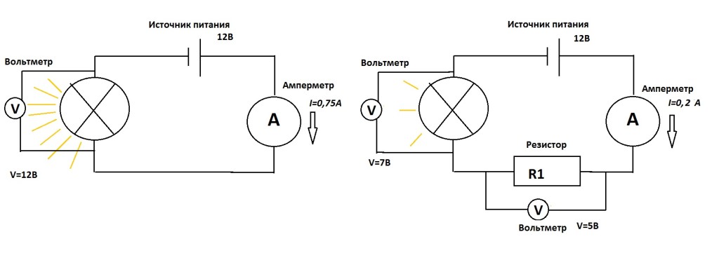
Consider work resistor on the example of a light bulb in the diagram below. We have a power source, a light bulb, an ammeter that measures current passing through the chain. And Resistor. When resistor is absent in the circuit, a large current, for example, 0.75A. The light bulb burns brightly. A resistor was built into the circuit - the current had an insurmountable barrier flowing through the circuit current dropped to 0.2A. The light bulb is less bright. It is worth noting that the brightness with which the light bulb burns also depends on the voltage on it. The higher the voltage, the brighter.
In addition, on resistor going on voltage drop. The barrier not only delays current, but also "eats" part of the voltage applied by the power source to the circuit. Consider this fall in the figure below. We have a 12 volt power supply. Just in case, an ammeter, two voltmeters in reserve, a light bulb and resistor. Turn on the circuit without resistor(left). The voltage at the bulb is 12 volts. We connect the resistor- part of the voltage fell on it. The voltmeter (bottom right in the diagram) shows 5V. The remaining 12V-5V = 7V remained on the light bulb. The voltmeter on the bulb showed 7V.
Of course, both examples are abstract, inaccurate in terms of numbers and are designed to explain the essence of the process taking place in resistor.
Resistor resistance unit
Main characteristic resistor - resistance. unit of measurement resistance- Ohm (Ohm, Ω). The more resistance, the larger current it is able to limit, the more heat it gives off, the more voltage drops On him.
Ohm's law for an electrical circuit
Basic law of all electricity. Links Voltage(V), Force current(I) and Resistance (R).
You can interpret these symbols in human language in different ways. The main thing is to be able to apply for each specific chain. Let's use Ohm's law for our circuit resistor and the light bulb discussed above, and calculate resistor resistance, at which current from a 12V power supply will be limited to 0.2. In this case, we consider the resistance of the light bulb to be 0.
V=I*R => R=V/I => R= 12V / 0.2A => R=60Ohm
So. If embedded in a circuit with a power source and a light bulb whose resistance is 0, resistor 60 ohm nominal, then current flowing through the circuit, will be 0.2A.
Resistor power characteristic
Microproger, know and remember! Parameter resistor power is one of the most important when constructing circuits for real devices.
Power electric current in any section of the circuit is equal to the product of the current flowing through this section by voltage in this part of the chain. P=I*U. Unit of measure 1W.
When current flows through resistor work is being done to limit the electrical current. When work is done, heat is released. Resistor dissipates this heat environment. But if resistor will do too much work, release too much heat - it will no longer have time to dissipate the heat generated inside it, it will heat up very much and burn out. What happens as a result of this incident depends on your personal luck factor.
The power rating of a resistor is the maximum current it can handle without overheating.
Resistor Power Calculation
Calculate resistor power for our light bulb circuit. So. We have current passing through the chain (and hence through resistor), equal to 0.2A. Voltage drop across the resistor equal to 5V (not 12V, not 7V, namely 5 - the same 5 that the voltmeter shows on resistor). It means that power current through resistor equal to P=I*V=0.2A*5V=1W. We conclude: resistor for our circuit must have a maximum power not less than (and preferably more than) 1W. Otherwise, it will overheat and fail.
Connection of resistors
Resistors in electric circuits have serial and parallel connection.
At serial connection general resistor resistance is the sum resistance everyone resistor in connection:

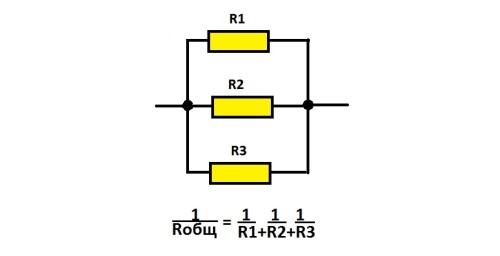
At parallel connection general resistor resistance calculated by the formula:
Do you have any questions? Write a comment. We will answer and help you figure it out =)
In electrical engineering, it is generally accepted that a simple circuit is a circuit that is reduced to a circuit with one source and one equivalent resistance. You can collapse the circuit using the equivalent transformations of serial, parallel and mixed connections. The exception is circuits containing more complex star and delta connections. Calculation of DC circuits produced using Ohm's and Kirchhoff's law.
Example 1
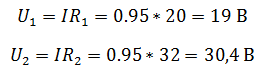
Two resistors connected to the source constant voltage 50 V, with internal resistance r = 0.5 ohm. Resistors R1= 20 and R2= 32 ohm. Determine the current in the circuit and the voltage across the resistors.
Since the resistors are connected in series, the equivalent resistance will be equal to their sum. Knowing it, we use Ohm's law for a complete circuit to find the current in the circuit.
Now knowing the current in the circuit, you can determine the voltage drops across each of the resistors.
There are several ways to check the correctness of the solution. For example, using Kirchhoff's law, which states that the sum of the EMF in the circuit is equal to the sum of the voltages in it.

But with the help of Kirchhoff's law, it is convenient to check simple circuits that have one circuit. A more convenient way to check is power balance.
The power balance must be observed in the circuit, that is, the energy given off by the sources must be equal to the energy received by the receivers.
The source power is defined as the product of the EMF and the current, and the power received by the receiver is the product of the voltage drop and the current.
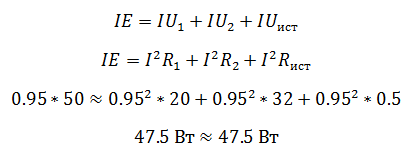
The advantage of checking the power balance is that you do not need to make complex cumbersome equations based on Kirchhoff's laws, it is enough to know the EMF, voltages and currents in the circuit.
Example 2
Total current in a circuit containing two resistors connected in parallel R 1 =70 ohm and R 2 \u003d 90 Ohm, equal to 500 mA. Determine the currents in each of the resistors.

Two resistors connected in series are nothing more than a current divider. You can determine the currents flowing through each resistor using the divider formula, while we do not need to know the voltage in the circuit, we only need total current and resistor resistances.
currents in resistors 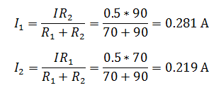
In this case, it is convenient to check the problem using the first Kirchhoff law, according to which the sum of the currents converging in the node is equal to zero.
If you do not remember the current divider formula, then you can solve the problem in another way. To do this, you need to find the voltage in the circuit, which will be common to both resistors, since the connection is parallel. In order to find it, you must first
We advise you to read
, diagnosis, treatment Treatment of urogenital chlamydia") Chlamydia urogenital - description, causes, symptoms (signs), diagnosis, treatment Treatment of urogenital chlamydia
Chlamydia urogenital - description, causes, symptoms (signs), diagnosis, treatment Treatment of urogenital chlamydia The benefits and significance of hydroamino acid threonine for the human body L threonine what
 To wait or not to wait for a guy from the army For what reason can they be commissioned from the army
 Baked apples with cottage cheese Baked apples with cottage cheese

