§ 111. METHODS OF EXCITATION OF DC GENERATORS
Generators direct current can be made with magnetic and electromagnetic excitation. To create a magnetic flux in generators of the first type, permanent magnets are used,
and in generators of the second type - electromagnets. Permanent, magnets are used only in machines of very low power. Thus, electromagnetic excitation is the most widely used method for creating magnetic flux. With this method of excitation, the magnetic flux is created by the current flowing through the excitation winding.
Depending on the method of supplying the excitation winding, DC generators can be independently excited and self-excited.
With independent excitation (Fig. 143, a), the excitation winding is connected to the network of an auxiliary DC energy source. To regulate the excitation current Iv, resistance r p is included in the winding circuit. With such excitation, the current Iv does not depend on the current in the armature Ia.
The disadvantage of generators independent excitation is the need for an additional source of energy. Despite the fact that this source usually has a low power (a few percent of the power of generators), the need for it is a great inconvenience, so independent excitation generators find very limited use only in machines. high voltage, in which the supply of the excitation winding from the armature circuit is unacceptable for design reasons.
Self-excited generators, depending on the inclusion of the excitation winding, can be parallel (Fig. 143, b), series (Fig. 143, c) and mixed (Fig. 143, d) excitation.
For parallel excitation generators, the current is small (a few percent rated current armature), and the excitation winding has a large number of turns. With series excitation, the excitation current is equal to the armature current and the excitation winding has a small number of turns.
With mixed excitation, two excitation windings are placed on the poles of the generator - parallel and series.
The process of self-excitation of DC generators proceeds in the same way for any excitation scheme. So, for example, in parallel excitation generators, which have received the widest application, the self-excitation process proceeds as follows.
Any prime mover rotates the armature of the generator, the magnetic circuit (yoke and cores of the poles) which has a small residual magnetic flux F 0 . This magnetic flux in the winding of the rotating armature is induced e. d.s. E 0 , which is a few percent of the rated voltage of the machine.
Under the influence of e. d.s. E 0 in a closed circuit consisting of an armature and an excitation winding, a current Iv flows. The magnetizing force of the excitation winding Ivw (w is the number of turns) is directed in accordance with the flow of residual magnetism, increasing the magnetic flux of the machine F, which causes an increase in both e. d.s. in the armature winding E, and the current in the excitation winding Iv. An increase in the latter causes a further increase in F, which in turn increases E and Iv.
Due to the saturation of the steel of the magnetic circuit of the machine, self-excitation does not occur indefinitely, but up to a certain voltage, depending on the speed of rotation of the armature of the machine and the resistance in the excitation winding circuit. When the steel of the magnetic circuit is saturated, the increase in the magnetic flux slows down and the process of self-excitation ends. Increasing the resistance in the excitation winding circuit reduces both the current in it and the magnetic flux excited by this current. Therefore, the emf decreases. With. and the voltage to which the generator is excited.
Changing the rotation speed of the generator armature causes a change in emf. s, which is proportional to the speed, as a result of which the voltage to which the generator is excited also changes.
Self-excitation of the generator will occur only under certain conditions, which are as follows:
1. >Presence of residual magnetism flow. In the absence of this flow, e will not be created. d.s. E 0, under the influence of which a current begins to flow in the excitation winding, so that the excitation of the generator will be impossible. If the machine is demagnetized and has no residual magnetization, then a direct current must be passed through the excitation winding from some extraneous source of electrical energy. After turning off the excitation winding, the machine will again have a residual magnetic flux.
2. The excitation winding must be connected in accordance with the flow of residual magnetism, i.e. so that the magnetizing force of this winding increases the flow of residual magnetism.
When the excitation winding is turned on in the opposite direction, its magnetizing force will reduce the residual magnetic flux and, during prolonged operation, can completely demagnetize the machine. If the excitation winding turned out to be turned on in the opposite direction, then it is necessary to change the direction of the current in it, i.e., swap the wires suitable for the terminals of this winding.
3. The resistance of the excitation winding circuit must be excessively large; with a very high resistance of the excitation circuit, self-excitation of the generator is impossible.
4. The resistance of the external load must be large, since with a low resistance, the excitation current will also be small and self-excitation will not occur.
The properties of a DC generator are mainly determined by the way the field winding is powered. Depending on this, the following types of generators are distinguished:
1) with independent excitation - the excitation winding is powered by an external DC source;
2) with parallel excitation- the excitation winding is connected to the armature winding in parallel with the load;
3) with sequential excitation- the excitation winding is connected in series with the armature winding and the load;
4) with mixed excitation - there are two excitation windings: one is connected in parallel with the load, and the other is connected in series with it.
The generators of the considered types have the same device and differ only in the implementation of the excitation winding. Windings of independent and parallel excitation, having a large number of turns, are made from a wire of small cross section; a series excitation winding with a small number of turns - from a wire of large cross section. Low power generators are sometimes made with permanent magnets. The properties of such generators are close to those of generators with independent excitation.
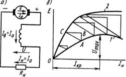
Generator with independent excitation. In this type of generator (Fig. 10.35) excitation current I in independent of armature currentI a , which is equal to the load currentI n . Current I in determined only by the position of the adjusting rheostatRp . B, included in the excitation winding circuit:
I b= U b (R b + R p.b),(10.33)
where U B - power supply voltage;R B - excitation winding resistance;Rp in - resistance of the adjusting rheostat.
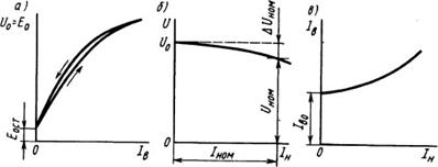
Typically, the excitation current is small and amounts to 1 ... 3% of the rated armature current. The main characteristics that determine the properties of DC generators are as follows: idle, external, control and load. Idling characteristic (Fig. 10.36, a) called addictionU 0 = f( l B) at I n = 0 and n = const . When the machine is idling, when the load circuit is open, the voltageU o at the terminals of the armature winding is equal to the EMF E 0 \u003d c e F p. Armature speedη is maintained unchanged, and the voltage at idle depends only on the magnetic flux F, i.e., the excitation currentI in . Therefore, the characteristicU 0 = f( I B) similar to the magnetic characteristic Ф = f( I in ). The idling characteristic is easy to obtain experimentally. To do this, first set the excitation current so thatU o 1.25 U NOM , then reduce the excitation current to zero and again increase it to the previous value. In this case, the ascending and descending branches of the characteristic are obtained, which come out of the same point. The divergence of the branches is explained by the presence of hysteresis in the magnetic circuit of the machine. AtI in = 0 in the armature winding, residual EMF is induced by the flow of residual magnetism E stop , which is 2...4% of U nom .
The external characteristic (Fig. 10.36.6) is the dependence U = f( I m ) at P - const and I in = const . In load mode, generator voltage
(10.34)
where Σ R a - the sum of the resistances of all windings connected in series in the armature circuit (armature windings, additional poles and compensation).
With increasing load to decrease voltage U affect: voltage drop during internal resistance Σ Ra cars; decrease in emfΕ as a result of the demagnetizing action of the armature reaction.
Voltage change during the transition from rated load mode to idle mode
Δ u = ( U 0 - U ΗΟΜ )/ U ΗΟΜ . (10.35)
For generators with independent excitation, it is 5 ... 15%.
Rice. 10.36.Characteristics of the generator with independent excitation
(a-c)
Regulating characteristic (Fig. 10.36, in) is called dependenceI in = f( I m ) at U= const and n = const . It shows how the field current should be adjusted to keep the generator voltage constant when the load changes. Obviously, in this case, as the load increases, it is necessary to increase the excitation current.
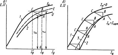
The load characteristic (Fig. 10.37, a) is the dependenceU= f( I B) at n = const and / n = const . Load characteristic atI n = I nom (curve 2) passes below the idling characteristic (curve 1), which can be considered as a special case of the load characteristic atI n = 0. The difference between the ordinates of curves 1 and 2 is due to the demagnetizing effect of the armature reaction and the voltage drop in the internal resistanceΣ Ra cars.
Rice. 10.37.Load characteristic of a generator with independent excitation (a) and its construction using a characteristic triangle (b)
A visual representation of the influence of these factors gives characteristic, or reactive, LAN triangle. If to the segment a A, equal on a certain scale to the voltageU, at some load currentI n and excitation currentI in add segment AB, equal on the same scale to the voltage dropI BΣ Ra in the generator, we get the segment aB, equal emf E.
At idle EMFΕ induced in the armature winding at a lower currentI" in , corresponding to the abscissa of the point FROM. Therefore, the segment Sun characterizes the demagnetizing effect of the armature reaction on the scale of the excitation current. At constant currentI n leg AB characteristic triangle is constant; leg Sun depends not only on currentI n , but also on the degree of saturation of the magnetic system, i.e. on the excitation currentI in . However, in some cases, the influence of the excitation current is neglected and it is assumed that the segment Sun proportional to current onlyI n .
This assumption allows us to build load characteristics at different currents, changing only the length of all sides of the triangleABC. If the vertex C of the characteristic triangle constructed for some currentI n , located on the characteristic 1 idling (Fig. 10.37, b), and then the triangle moves along this characteristicABC so that catet Sun remains parallel to the x-axis, then the trace of the point BUT shows approximately the desired load characteristic 2 at a given current valueI n . This characteristic is somewhat different from the actual characteristic. 3 (which can be removed empirically), since the value of the leg Sun characteristic triangle changes due to changing saturation conditions. Using the characteristic of idling with the help of a characteristic triangle, it is possible to construct other characteristics of the generator: external and adjusting.
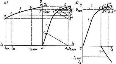
The external characteristic is built on the basis of the idling characteristic 1 (Fig. 10.38, a). Taking a pointD on the y-axis corresponding to the rated voltageU nom , a straight line is drawn through itAD, parallel to the x-axis. The vertex is located on this line. BUT characteristic triangle taken at rated armature current so that the leg AB was parallel to the y-axis, and vertex C was on characteristic 1 . Then, dropping the perpendicular from the vertex BUT on the x-axis, find a point And to, corresponding to the rated excitation currentI vnom . When determiningI vnom take into account that under the action of the armature reaction, the EMF at load is less than at idle, i.e., it is created, as it were, by a smaller excitation current.
Rice. 10.38. Charts for constructing external (a) and adjusting (b)
characteristics of the generator with independent excitation using
characteristic triangle
Decreasing current I in corresponds to the segment sun, characterizing the demagnetizing effect of the armature reaction. The voltage at rated current is also less than the EMF by the amount of voltage dropI aΣ Ra, to which the leg corresponds AB.
When constructing the desired dependence 2, i.e., voltageU from load current 1 a, its two points can be easily determined: the rated currentI anom corresponds to the rated voltageU HOM (point b ), and the armature current, equal to zero (idle mode), is the voltageU o (dot a), equal to EMF at excitation currentI vnom . Other points (with,d etc.) of the external characteristic can be constructed by changing all sides of the characteristic triangle in proportion to the change in the armature current and arranging it so that the legs A"B", A"B",... remained parallel to the y-axis. At the same time, the points B, B" B" should be on a vertical line A K B corresponding to the excitation currentI in.nom , and points C, C", C", ... - on the characteristic of idling 1 . Then the ordinates of the points A, A,... will determine the desired voltage value at load currents 1 a1 \u003d 1 anom A "B" / AB, 1 a2 \u003d \u003d 1 anom A "B" / AB etc. Usually, when constructing an external characteristic, only the hypotenuses of the characteristic triangles are drawn A "C", A "C""",..., parallelACup to the intersection with the idling characteristic and with the line A K V. Ordinates of found points A", A"... determine the desired stress values (i.e., points c,d external characteristics 2) at load currentsIa nom , I a 1 , 1 a2.
If from a point A to draw a line parallel AU, to the intersection with the idling characteristic at point C to, then you can get the current value short circuit 1 k \u003d 1 anom A to C to /AC, which is 5 ... 15 times the rated current. Knowing the short-circuit current, you can calculate maximum moment, the mechanical strength of the shaft and select the parameters of the protection equipment. Experimental determination of short-circuit current difficult, since in the process of conducting the experiment, an all-round fire may occur.
The constructed characteristic is approximate. Its main error is due to the fact that the demagnetizing effect of the armature reaction (i.e., the leg sun) not proportional to armature current. Usually, the given construction gives a somewhat underestimated value of the short-circuit current.
The adjustment characteristic (Fig. 10.38, b) is built as follows. First find the excitation current I in0 , corresponding to the rated voltage at no load. To determine the excitation current at rated load current, the top BUT characteristic triangle (corresponding to the rated load) is placed on a straight line 2, parallel to the abscissa axis and located at a distance from itUHOM. leg AB must be parallel to the y-axis, and the vertex FROM should be located on the idling characteristic 1. Apex abscissa BUT gives the desired value of the excitation current.
The proof of the validity of this construction is given in the construction of the external characteristic. Drawing lines parallel to the hypotenuse BUT C, we get segments A"C", A"C",..., concluded between the idling characteristic 1 and line 2 corresponding to the conditionU= UHOM = const. These segments represent the hypotenuses of the characteristic triangles at different load currents. Desired control characteristicI B= f( I a) - curve 3 - built in the lower coordinate corner. The values of the excitation current are determined by the abscissas of the points A, A", A",..., which correspond to load currents proportional to the lengths of the segments BUT FROM, BUT"FROM", A "C"...
The advantage of generators with independent excitation - the ability to regulate the voltage over a wide range from zero to Umaxby changing the excitation current and a relatively small change in voltage under load. However, to power the excitation winding of such generators, external DC sources are required.
Generators with independent excitation are used only at high power, as well as at low power, at low voltage. Regardless of the value of the armature voltage, the field winding is designed for a standard DC voltage of 110 or 220 V to simplify the control equipment.
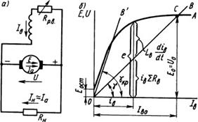
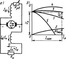
Rice. 10.39. circuit diagram generator with parallel excitation (a) and the dependence of the change in EMF and the voltage drop in the excitation circuit i Β Σ R Β when changing the excitation current of the generator (b)
Generator with parallel excitation. AT this generator (Fig. 10.39, a) the excitation winding is connected through an adjusting rheostat in parallel with the load. Therefore, in this case, the self-excitation principle is used, in which the excitation winding is powered directly from the generator armature winding. Self-excitation of the generator is possible only under certain conditions. To establish them, consider the process of changing the current in the circuit "field winding - armature winding" in the idle mode. For the circuit under consideration, we obtain the equation
![]() (10.36)
(10.36)
where e and i in - instantaneous values of EMF in the armature winding and excitation current;Σ R in = Rin + Rr.v - the total resistance of the generator excitation circuit (resistanceΣ R α can be neglected since it is much lessΣ R in); L B - total inductance of the excitation and armature windings. All members of equation (10.36) can be depicted graphically (Fig. 10.39, b). EMF e at some value i in excitation current can be determined from the characteristic OA idling of the generator, and the voltage dropiinΣ R in- according to the current-voltage characteristic OV its excitation circuits. Characteristic OV is a straight line passing through the origin at an angleγ to the x-axis; whereintgγ = Σ R B. From (10.36) we have
![]() (10.37)
(10.37)
Therefore, if the difference ( e - i BΣ R B) > 0, then the derivativedi/ dt > 0, and there is a process of increasing the excitation currenti in .
The steady state in the excitation winding circuit is observed whendi B/ dt = 0, i.e. at the point of intersection FROM idle characteristics OA with a straight line OV. In this case, the machine operates with a certain steady excitation current I v0 and emf E 0 = U 0 .
From equation (10.37) it follows that for the self-excitation of the generator, certain conditions must be met:
1) the self-excitation process can start only if at the initial moment(i Β = 0) some initial EMF is induced in the armature winding. Such an emf can be created by the flow of residual magnetism, therefore to start the process of self-excitation, it is necessary that the generator has a flow of residual magnetism, which, when the armature rotates, induces it in the EMF winding E OST. Usually there is a flow of residual magnetism in the machine due to the presence of hysteresis in its magnetic system. If there is no such flow, then it is created by passing a current from an external source through the excitation winding;
2) during the passage of currenti in according to the excitation winding of its MDSF sshould be directed according to MDS residual magnetism F0CT . In this case, under the influence of the difference e - i B Σ R B there is an increase in current i in , excitation magnetic flux Ф in and EMF e. If these MMFs are directed oppositely, then the MMF of the excitation winding creates a flow directed against the flow of residual magnetism, the machine is demagnetized and the self-excitation process will not be able to start;
3) positive difference e - i B ∑ R B required to increase the excitation current i in zero to steady stateI in0 , can occur only if in the specified range of current changei in straight OV located below the idle speed characteristic OA. With an increase in the resistance of the excitation circuitΣ R B the angle of inclination increasesγ straight OV to the current axisI in and at some critical angleγ cr (corresponding to the critical resistance valueΣ R B. Kp) straight O V practically coincides with the rectilinear part of the idling characteristic. In this case e i In Σ R in and the process of self-excitation becomes impossible. (Consequently, for self-excitation of the generator, it is necessary that the resistance of the excitation circuit be less than the critical value.
If the parameters of the excitation circuit are chosen so thatΣR in Σ R in.cr , then at the point FROM stability of the self-excitation mode is ensured. With an accidental decrease in currenti in below the established valueI in0 or increase it overI in0 there is a positive or negative difference, respectively. (e - i B Σ R B ) seeking to change
Rice. 10.40.External characteristics of generators with independent (2)
and parallel (1) excitation
current i in so that it becomes equal again I in0 . However, for Σ R B> Σ R B . Kp the stability of the self-excitation regime is violated. If, during the operation of the generator, the resistance of the excitation circuit is increasedΣR in to a value greaterΣ R in .cr , then its magnetic system is demagnetized and the EMF decreases toΕ ο With t . If the generator started work at
Σ R B > Σ R B . kr , then it will not be able to self-excite. Consequently, condition Σ R in Σ R c.c. R limits the possible range of regulation of the generator excitation current and its voltage. It is usually possible to decrease the generator voltage by increasing the resistanceΣ R B , only up to (0.6...0.7) Unom.
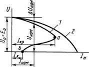
The external characteristic of the generator is the dependence U= f(I m ) at n = const and R B = const (Fig. 10.40, curve 1). It is located below the external characteristic of the generator with independent excitation (curve 2). This is due to the fact that in the considered generator in addition to two reasons that cause a decrease in voltage with increasing load (voltage drop in the armature and the demagnetizing effect of the armature reaction), there is a third reason-reduction of excitation current 1 V = = U/ ΣR in , which depends on the voltage U, i.e. from the currentIn.
The generator can only be loaded up to a certain maximum current I kr . With a further decrease in load resistanceR H current I H= U/ R H begins to decrease as the voltageU falling faster than decreasingR H. Work on the site a b external characteristics are unstable; in this case, the machine switches to the operating mode corresponding to the pointb, i.e. in short circuit mode.
The action of the causes that cause a decrease in the generator voltage with increasing load is especially clearly seen from the consideration of Fig. 10.41, which shows the construction of an external characteristic according to the idling characteristic and the characteristic triangle.
The construction is carried out in the following order. Through the dotD on the ordinate axis corresponding to the rated voltage, a straight line is drawn parallel to the abscissa axis. The vertex is located on this line. BUT characteristic triangle corresponding to the nominal
Rice. 10.41. Graphs for constructing the external characteristics of the generator with
parallel excitation using a characteristic triangle
load; leg A B must be parallel to the y-axis, and vertex C must lie on the idling characteristic 1. Through origin and vertex BUT direct 2 to the intersection with the idling characteristic; this straight line is the current-voltage characteristic of the resistance of the excitation winding circuit. On the ordinate of the point of intersectionΕ characteristics 1 and 2 get generator voltageU 0 = E 0 at idle.
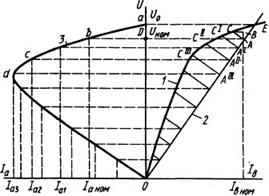
Excitation current I in rated at nominal mode corresponds to the abscissa of the point BUT, and generator EMF E nom at rated load - point ordinate AT. It can be determined from the idling characteristic if the excitation current is reducedI in rated for the length of the segment sun, taking into account the demagnetizing effect of the armature reaction. When constructing an external characteristic 3 her points a and b , corresponding to no-load and rated load, are determined by voltagesU o and u hom . Intermediate points with,d, ... obtained by drawing direct BUT"FROM", A"C", A""C"",..., parallel to the hypotenuse AU, before crossing with the current-voltage characteristic 2 at points A", A", A",..., as well as with idling characteristic 1 at points С", С", С"",.... Ordinates of points A "A" A "", ... correspond to voltages at load currents I a 1 , I a 2 , I a 3 ,..., whose values are determined from the relation
I anom:I a1:I a2 ,I a3 = AC:A"C":A"C":A""C"":...
When switching from the rated load mode to the idle mode, the generator voltage changes by 10 ... 20%, i.e. more than in a generator with independent excitation.
With a steady short circuit of the armature, the current I to generator with parallel excitation is relatively small
Rice. 10.42. Generator circuit with sequential excitation (a)
and its external characteristic ( b)
(see Fig. 10.41), since in this mode the excitation voltage and current are zero. Therefore, the current to. only EMF is created from residual magnetism and is (0.4 ... 0.8)I nom .
The control and load characteristics of a generator with parallel excitation are of the same nature as those of a generator with independent excitation.
Most of the DC generators produced by the domestic industry have parallel excitation. To improve external performance, they usually have a small series winding (one to three turns per pole). If necessary, such generators can also be switched on according to a scheme with independent excitation.
Generator with sequential excitation. AT generator with sequential excitation (Fig. 10.42, a) excitation current I in = I a = I n . The external characteristic of the generator (Fig. 10.42, b, curve 1) can be built from the idling characteristic (curve 2) and the reaction triangleABC, the sides of which increase in proportion to the currentI n . For currents lessI kr , with an increase in the load current, the magnetic flux increasesΦ and generator emf E, As a result, the voltage also increases.U. Only for high currents I n > I kr voltage U decreases with increasing load, since in this case the magnetic system of the machine is saturated and a small increase in fluxΦ cannot compensate for the increase in voltage drop across the internal resistanceΣ R a. Since in a series-excited generator, the voltage varies greatly with a change in load, and at idle it is close to zero, such generators are unsuitable for powering most electrical consumers. They are used only for electric braking of engines with sequential excitation, which are then transferred to the generator mode.
Rice. 10.43.Mixed excitation generator circuit (a)
and its external characteristics (b)
Mixed generator arousal. In this generator (Fig. 10.43, a) There are two excitation windings: main (parallel) and auxiliary (serial). Consistent inclusion of two windings allows you to get an approximately constant generator voltage when the load changes.
The external characteristic of the generator (Fig. 10.43, b) in the first approximationcan be represented as the sum of the characteristics created by each of the excitation windings. When one parallel winding is turned on, through which the excitation current passes I in 1 , generator voltageU gradually decreases with increasing load currentI n (curve 1). When one series winding is turned on, through which the excitation current passes I in 2 = In, voltage increases with currentI n (curve 2).
By selecting the number of turns of the series winding so that at rated load the voltage generated by itΔ U last compensated for the total voltage dropΔ U when operating the machine with only one parallel winding, it can be achieved that the voltageU when the load current changes from zero toI nom remained almost unchanged (curve 3). In practice, it varies within 2...3%. By increasing the number of turns of the series winding, one can obtain a characteristic at which the voltageUHOM > U o (curve 4); this characteristic compensates for the voltage drop not only in the internal resistanceΣ Ra generator, but also in the line connecting it to the load. If the serial winding is turned on so that the MMF is directed against the MMF of the parallel winding (opposite connection), then the external characteristic of the generator with a large number of turns of the series winding will be steep (curve 5). The counter-connection of serial and parallel excitation windings is used in welding generators and other special machines where it is required to limit the short-circuit current.
Generator operation at variable speed. Generators installed on cars, tractors, railway cars, airplanes, etc., are usually
Rice. 10.44.Idling characteristics (a) and external (b) generator with
parallel excitation at different speeds
are driven by an engine that provides propulsion vehicle, or from the axis of its wheels. The frequency of rotation of such a generator changes in accordance with the speed of the vehicle.
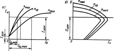
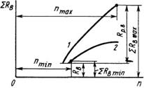
For generators operating in the mode under consideration, the main characteristics are usually given for three values of rotational speeds: minimum, average and maximum (Fig. 10.44). Feature generators, the rotational speed of which varies over a wide range, is that, starting from n wed and higher, they work with a weak or completely unsaturated magnetic circuit. This is due to the desire to reduce the excitation currents during idlingI B 0 max and AT load that occur at a speed of rotationnmin, to create more favorable working conditions for the voltage regulator. The most difficult mode for the drive of the generator in question is the mode with the minimum rotational speed, since in this case, in order to provide the necessary powerΡ required to have the highest torque. Therefore, in some cases, the power is limited, i.e., the generator current at a speed of rotationnmin.
For generators with parallel excitation operating at a variable speed, in addition to the above three self-excitation conditions, there are three additional ones. At speeds below p t in the generator should run at idle. If at n nmin connect a large load to the generator, then due to a significant voltage drop in the armature circuit, the voltage at its terminals will drop to almost zero and the self-excitation process will not start. Therefore, in the vehicle power supply system,
Rice. 10.45. Graphs of changes in the EMF and voltage of the generator for various
speeds and resistances of the excitation circuit
be provided with equipment that prevents the possibility of connecting
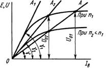
to the load generator n nmin. The resistance of the excitation circuit must be below the critical resistance for any given speed. Therefore, for fast self-excitation of the generator, it is recommended not to introduce any additional resistors into the excitation circuit when accelerating the vehicle. If we decrease the speed P, then, accordingly, the idling characteristic will shift down (Fig. 10.45) and the critical resistance will decrease, at which the process of self-excitation of the generator is impossible. So, for the speed n ί critical resistance corresponds to a straight line OA 1 with an angleγ and and for the speed n 2 - straight OA 2 with an angle γ 2 Therefore, a generator with an excitation circuit resistance corresponding to a straight line OA 2 , can work normally at rotation speed n 1, but will not be able to self-excite at a frequency n 2 . At a rotational speed p 1 depending on the resistance value of the excitation circuit, the generator voltage turns out to be equal toU 01 or U 02 .
For each resistance of the excitation circuit, you can select the rotational speed P, at which this resistance becomes critical. This speed is called "dead". The “dead” rotational speed for the excitation winding itself without additional resistors will be the lowest frequency below which the self-excitation process is impossible. Therefore, in some cases, to accelerate the excitation of the generator during acceleration of the vehicle, the excitation winding is supplied with power from the battery using a relay.
When changing the direction of rotation of the generator armature, the direction of the current in the field winding must remain unchanged so that the magnetic flux created by the winding does not destroy the flow of residual magnetism. This is usually achieved by switching the wires connecting the excitation winding to the brushes of the machine.
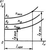
On fig. 10.46 , a the adjusting characteristics of the generator with parallel excitation are given, built for three values of the speed. pointsA 1 , A 2 and A 3 of these characteristics correspond to the idling mode.
Rice. 10.46.Adjusting (a) and speed adjusting (b) characteristics
According to the regulation characteristics, it is possible to determine the range of change in the excitation current necessary to stabilize the generator voltage at the level U Η0Μ when changing speed and load. Lowest currentI b. min corresponds to the speed n max and idling machine, the highest current I in m ah - speednmin and rated load.
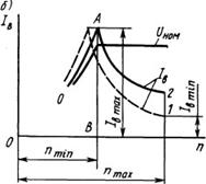
Speed adjustment characteristics (Fig. 10.46, b) are the dependences of the excitation currentI in from rotational speed n at constant voltageU at the terminals of the generator. Usually they are built for rated voltage U nom at idle (curve 1) and rated load (curve 2). They can also be used to determine the range of change in the excitation current required to maintain a stable voltage across the load. Attitude k i = I in m ah / I in m 1p called excitation current control factor; usually it is 8 ... 12. In practice, when obtaining these characteristics, a part of the self-excitation characteristic is also determined (section OA) with a constant resistance of the excitation circuit. This allows you to determine the initial rotational speeds nmin , at which the generator develops the rated voltage at idle and at rated load. Under load speed p t iPmore than at idle, due to the voltage drop in the armature circuit. The lower the resistance of the excitation circuit, the lower the speednmin.
The maximum excitation current for this generator corresponds to the segment AB. Upon reachingUH 0 M excitation current with further increase n decreases approximately according to the hyperbolic law. However, at high values of the excitation current, due to saturation
Rice. 10.47.Rheostatic control characteristics
magnetic circuit of the machine, these characteristics differ significantly from hyperbole.
With all methods of regulating the generator voltage, the necessary change in the excitation current is carried out by changing the resistance of the excitation circuitΣ R B (to change Σ R B the action of pulsed transistor or thyristor voltage regulators can also be reduced). On fig. 10.47 resistance dependences are shownΣ R B from rotational speedη at constant voltage U and constant load, built for idle modes (curve 1) and rated load (curve 2). According to the characteristics, it is possible to determine the coefficient of regulation of the resistance of the excitation circuit k rv = Σ R in max / Σ R Bmin and additional resistanceRpB, which must be entered during regulation in the excitation circuit, in series with the resistanceR B the excitation winding itself.
§ 111. Methods of excitation of DC generators
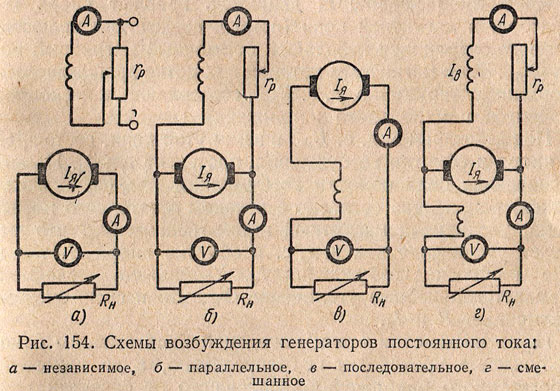
Depending on the method of supplying the excitation winding, modern DC generators use independent excitation of the magnetic flux and self-excitation.
With independent excitation (Fig. 154, a), the excitation winding is connected to an auxiliary DC energy source. To control the excitation current I resistance is turned on in the winding circuit r p . With this excitation, the current I in does not depend on the current in the armature I I.
The disadvantage of independent excitation generators is the need for an additional source of energy. Despite the fact that this source usually has a low power (a few percent of the power of the generators), the need for it is a great inconvenience and therefore independent excitation generators are of limited use in special installations (GD) and in high voltage machines, in which the excitation winding is powered from armature chain is unacceptable for design reasons.
Self-excited generators have more wide application. Depending on the connection of the excitation winding, they can be parallel (Fig. 154, b), serial (Fig. 154, c) and mixed (Fig. 154, d) excitation.
For generators of parallel excitation, the current I in small (a few percent of the rated armature current), and the excitation winding has a large number of turns. With series excitation, the excitation current is the armature current and the excitation winding has a small number of turns.
With mixed excitation, two excitation windings are placed on the poles of the generator - parallel and series.
The process of self-excitation of DC generators proceeds in the same way for any excitation scheme. Let us consider the process of self-excitation of a parallel excitation generator, which has received the widest application.
Any prime mover rotates the armature of the generator, in the magnetic circuit (yoke and pole cores) of which a small residual magnetic flux Φ rest is preserved. This magnetic flux in the winding of the rotating armature is induced e. d.s. E ost, which is a few percent of the rated voltage of the machine.
Under the influence of e. d.s. E ost in a closed circuit consisting of an armature and an excitation winding, a current flows I in. Magnetizing force of the field winding I in ω in (ω in - number of turns) is directed according to the flow of residual magnetism, increasing the magnetic flux of the machine Φ m, which causes an increase like e. d.s. in the armature winding E, and the current in the excitation winding I in. An increase in the latter causes a further increase in Φ m, which in turn increases E and I in.
Due to the saturation of the steel of the magnetic circuit of the machine, self-excitation does not occur indefinitely, but up to a certain voltage, depending on the speed of rotation of the armature of the machine and the resistance of the excitation winding circuit. When the steel of the magnetic circuit is saturated, the increase in the magnetic flux slows down and the self-excitation process ends. Increasing the resistance in the excitation winding circuit reduces both the current in it and the magnetic flux excited by this current. Therefore e decreases. d.s. and the voltage to which the generator is excited.
Changing the rotation speed of the generator armature causes a change in e. d.s., which is proportional to the speed, as a result of which the voltage to which the generator is excited also changes.
Self-excitation of the generator occurs only under certain conditions, which are as follows.
1. The presence of a flow of residual magnetism. In the absence of this flow, no e is created. d.s. E ost, under the action of which a current begins to flow in the excitation winding, so that the excitation of the generator will be impossible. If the machine is demagnetized and does not have residual magnetization, then a direct current from some extraneous source must be passed through the excitation winding electrical energy. After the excitation winding is disconnected, the residual magnetic flux will remain in the machine.
2. The excitation winding must be turned on so that the magnetizing force of this winding increases the flow of residual magnetism.
When the excitation winding is turned on in the opposite direction, its magnetizing force will reduce the residual magnetic flux and, during prolonged operation, can completely demagnetize the machine. In this case, it is necessary to change the direction of the current in the excitation winding, that is, to swap the wires suitable for its terminals.
3. The resistance of the field winding circuit should not be excessively large; with a very high resistance of the excitation circuit, self-excitation of the generator is impossible.
4. The resistance of the external load must be relatively large, since with a low resistance, the excitation current will also be small and self-excitation will not occur.
11. DC generator with parallel excitation: operating principle, self-excitation conditions, characteristics.
Shunt excitation generator. In this generator (Fig. 8.47, a) the excitation winding is connected through an adjusting rheostat in parallel with the load. Consequently, in this In this case, the self-excitation principle is used, in which the excitation winding is powered directly from the generator armature winding. Self-excitation of the generator is possible only under certain conditions. To establish them, consider the process of changing the current in the circuit "field winding - armature winding" in the idle mode. For the circuit under consideration, we obtain the equation
|
e = i in Σ R in + L in di in / dt, |
where e and i c - instantaneous values of EMF in the armature winding and excitation current; Σ R in = R in + R r.v - total resistance of the generator excitation circuit (resistance Σ R and can be neglected, since it is much less than Σ R in); L c is the total inductance of the excitation and armature windings. All terms included in (8.59) can be depicted graphically (Fig. 8.47, b). EMF e at some value i in the excitation current can be determined by the characteristic OA idling of the generator, and the voltage drop i in Σ R c - according to the current-voltage characteristic OV its excitation circuits. Characteristic OV is a straight line passing through the origin at an angle y to the x-axis; wherein tg γ= Σ R in. From (8.59) we have
|
di in / dt =(e-i in Σ R in)/ L in. |
Therefore, if the difference ( e - i in Σ R c) > 0, then the derivative di in / dt> 0, and there is a process of increasing the excitation current i in.
The steady state in the excitation winding circuit is observed when di in / dt= 0, i.e. at the point of intersection FROM idle characteristics OA with a straight line OV. In this case, the machine operates with a certain steady excitation current I v0 and emf E 0 = U 0 .
From equation (8.60) it follows that for the self-excitation of the generator, certain conditions must be met:
1) the self-excitation process can start only if at the initial moment ( i c \u003d 0) some initial EMF is induced in the armature winding. Such an EMF can be created by a flow of residual magnetism, therefore, to start the process of self-excitation, it is necessary that the generator has a flow of residual magnetism, which, when the armature rotates, induces an EMF in its winding E rest. Usually there is a flow of residual magnetism in the machine due to the presence of hysteresis in its magnetic system. If there is no such flow, then it is created by passing a current from an external source through the excitation winding;
2) during the passage of current i in the winding of its excitation MDS F in must be directed according to the MMF of residual magnetism F Oct. In this case, under the action of the difference e - i in Σ R in the process of increasing current i c, excitation magnetic flux F c and EMF e. If these MMFs are directed oppositely, then the MMF of the excitation winding creates a flow directed against the flow of residual magnetism, the machine is demagnetized and the self-excitation process will not be able to start;
3) positive difference e - i in Σ R c, necessary to increase the excitation current i from zero to steady state I v0, can occur only if in the specified range of current change i in a straight line OB located below the idle speed characteristic OA. With an increase in the resistance of the excitation circuit Σ R the angle of inclination increases γ straight OB to the current axis I in and at some critical value of the angle γ cr (corresponding to the critical resistance value Σ R c.cr) straight OV" practically coincides with the rectilinear part of the idling characteristic. In this case e≈ i in Σ R in and the process of self-excitation becomes impossible. Consequently, for self-excitation of the generator, it is necessary that the resistance of the excitation circuit be less than the critical value.
If the parameters of the excitation circuit are chosen so that Σ R in< ΣR v.cr, then at the point FROM stability of the self-excitation mode is ensured. With an accidental decrease in current i at below steady state I in 0 or increase it over I in0, a positive or negative difference arises, respectively ( e - i in Σ R c), seeking to change the current i in so that it becomes equal again I in0 . However, for Σ R c > Σ R c.cr stability of the self-excitation mode is violated. If, during the operation of the generator, the resistance of the excitation circuit is increased Σ R in up to a value greater than Σ R v.cr, then its magnetic system is demagnetized and the EMF decreases to E rest. If the generator started to work at Σ R c > Σ R v.kr, then he will not be able to self-excite. Consequently, conditionΣ R in< ΣR c.cr limits the possible range of regulation of the generator excitation current and its voltage. It is usually possible to decrease the generator voltage by increasing the resistance Σ R c, only up to (0.6-0.7) U nom. External characteristic of the generator is a dependency U=f(I m) at n= const and R in = const (curve 1, rice. 8.48). It is located below the external characteristic of the generator with independent excitation (curve 2). This is due to the fact that in the considered generator except for two reasons that cause a decrease in voltage with increasing
load (voltage drop in the armature and the demagnetizing effect of the armature reaction), there is a third reason - a decrease in the excitation current I in = U/Σ R in, which depends on the voltage U, i.e. on the current I n.
The generator can only be loaded up to a certain maximum current I cr. With a further decrease in load resistance R n current I n = U/R n begins to decrease, as the voltage U falling faster than decreasing R n. Work on the site ab external characteristics are unstable; in this case, the machine switches to the operating mode corresponding to the point b, i.e. in short circuit mode.
The action of the causes that cause a decrease in the generator voltage with increasing load is especially clearly seen from the consideration of Fig. 8.49, which shows the construction of an external characteristic according to the idling characteristic and the characteristic triangle.
The construction is carried out in the following order. Through the dot D on the ordinate axis corresponding to the rated voltage, a straight line is drawn parallel to the abscissa axis. The vertex is located on this line. BUT characteristic triangle corresponding to the rated load; leg AB must be parallel to the y-axis, and the vertex FROM must lie on the idling characteristic 1. Through origin and vertex BUT direct 2 to the intersection with the idling characteristic; this straight line is the current-voltage characteristic of the resistance of the excitation winding circuit. On the ordinate of the point of intersection E characteristics 1 and 2 get generator voltage U 0 = E 0 at idle.
Excitation current I in.nom at nominal mode corresponds to the abscissa of the point BUT, and generator EMF E nom at rated load - the ordinate of the point AT. It can be determined from the idling characteristic if the excitation current is reduced I v.nom by the length of the segment sun, taking into account the demagnetizing effect of the armature reaction. When constructing an external characteristic 3 her points a and b, corresponding to no-load and rated load, are determined by voltages U 0 and U nom. intermediate points With, d,... receive by spending
straight A"C", A"C", A""C"",..., parallel to the hypotenuse AC, before crossing with the current-voltage characteristic 2 at points A", A", A"",..., and also with the characteristic of idling 1 at points C", C", C"",.... Ordinates of points A "A" A "",... correspond to voltages at load currents I a1 , I a2 , I a3 ,..., whose values are determined from the relation
I a nom: I a 1:I a 2 ,Ia 3… = AC: A"C": A"C":A""C"" ...
When switching from the rated load mode to the idle mode, the generator voltage changes by 10 - 20%, i.e. more than in a generator with independent excitation.
With a steady short circuit of the armature, the current I to the generator with parallel excitation is relatively small (see Fig. 8.48), since in this mode the voltage and excitation current are zero. Therefore, the current to. only EMF is created from residual magnetism and is (0.4 - 0.8) I nom. The control and load characteristics of a generator with parallel excitation are of the same nature as those of a generator with independent excitation.
Most of the DC generators produced by the domestic industry have parallel excitation. To improve external performance, they usually have a small series winding (one to three turns per pole). If necessary, such generators can also be switched on according to a scheme with independent excitation.
The excitation of the generator is the creation of a working magnetic flux, due to which an EMF is created in the rotating armature. DC generators, depending on the method of connecting the excitation windings, are distinguished, independent, parallel, series and mixed excitation. The independent excitation generator has an excitation winding OB, connected to an external current source through an adjusting rheostat (Figure 6-10, a) The voltage at the terminals of such a generator ( curve 1 in Fig. 6-11) decreases somewhat with increasing load current as a result of the voltage drop across the internal resistance of the armature, and the voltages are always stable. This property turns out to be very valuable in electrochemistry (powering electrolytic baths)
The parallel excitation generator is a self-excited generator; the excitation winding of the OB is connected through an adjusting rheostat to the terminals of the same generator (Fig. 6-10, b). Such an inclusion leads to the fact that with an increase in the load current, the voltage at the generator terminals decreases due to the voltage drop across the armature winding. This, in turn,
causes a decrease in the excitation current and EMF in the armature. Therefore, the voltage at the terminals of the UH generator decreases somewhat faster (curve 2 in Fig. 6-11) than that of an independent excitation generator.
A further increase in load leads to such a strong decrease in the excitation current that when the load circuit is short-circuited, the voltage drops to zero (a small short-circuit current is due only to residual induction in the machine). Therefore, it is believed that the parallel excitation generator is not afraid of a short circuit.
The sequential excitation generator has an OB excitation winding connected in series with the armature (Fig. 6-10, e). In the absence of a load in the armature, a small EMF is nevertheless excited due to the residual induction in the machine (curve 3 in Fig. 6-11). With an increase in load, the voltage at the generator terminals first increases, and after reaching the magnetic saturation of the magnetic system of the machine, it begins to decrease rapidly due to the voltage drop across the armature resistance and due to the demagnetizing effect of the armature reaction.
Due to the large variability of the voltage with a change in load, series-excited generators are not currently used.
The mixed excitation generator has two windings: OB - connected in parallel to the armature, (additional) - in series (Fig. 6-10, d). The windings are switched on so that they create magnetic fluxes in one direction, and the number of turns in the windings is chosen so that the voltage drop on the internal resistance of the generator and the EMF of the armature reaction would be compensated by the EMF from the parallel winding flux.
We advise you to read
 Psychological characteristics of children in adolescence
 Transferring a child to another school - the procedure and necessary documents Whether to transfer a child to another school
, diagnosis, treatment Treatment of urogenital chlamydia") Chlamydia urogenital - description, causes, symptoms (signs), diagnosis, treatment Treatment of urogenital chlamydia
Chlamydia urogenital - description, causes, symptoms (signs), diagnosis, treatment Treatment of urogenital chlamydia The benefits and significance of hydroamino acid threonine for the human body L threonine what

