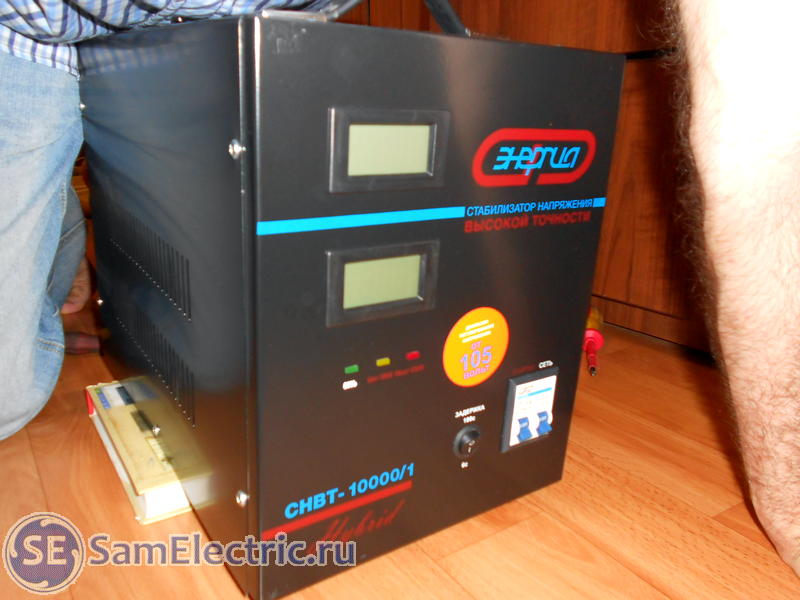
And this article describes how to properly connect a voltage stabilizer, and a real example is given, which shows the installation of a relay voltage regulator Energy SNVT-10000/1 Hybrid.
So, the voltage stabilizer is purchased. It is very good if you have a friend or have the opportunity to invite a specialist to connect the stabilizer. If this is not possible, then if you have elementary skills, making the connection yourself is also not so difficult.
Separate alarm relay. Field isolation relay that isolates the alternator from the battery when the ignition is off. Electromagnetic voltage regulator with two switches, found on some older generators. An older car may have a dynamo instead of a generator. The dynamo has a separate regulator, a control box that has three electromagnetic switches to control current, voltage and to turn off when needed to prevent the battery from draining through the dynamo.
Some generators have separate solenoid controls, and some have a separate field isolation relay, an electromagnetic switch that protects the generator when the ignition is turned off. Some vehicles have a separate control in the circuit for the warning light on the dashboard.
General information about the installation and operation of stabilizers
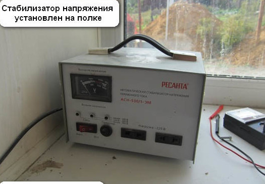
To begin with, choose a place to install the stabilizer, it should be dry, dust-free and easily ventilated. It is not recommended to install a stabilizer on the floor, it is better if it is a shelf, bedside table, table. The wall stabilizer in this sense is the most convenient.
The stabilizer itself must be carefully unpacked, familiarized with its external device, using the product passport. If the stabilizer was transported at sub-zero temperatures, it must be kept at room temperature for at least four hours before connection. This is due to the fact that all voltage stabilizers are primarily afraid of the formation of condensate inside. Therefore, you need to wait until it forms and dries.
Parallel Linear Voltage Regulators
Individual components are usually mounted on the bulkhead of the engine or sometimes on top of the generator itself. Linear regulators provide a simple, low noise control solution direct current. However, connecting linear regulators in parallel is not always straightforward. Sharing current with linear regulators is traditionally not as simple as connecting parts in parallel. Two reference-based linear regulators set to the same output voltage and with the outputs connected together will not share the same current.
At the time of connection, pay attention that the stabilizer is turned off - the power button is in the “Off” position and the stabilizer must be connected to a socket with grounding contacts (Euro socket), otherwise the stabilizer must be grounded separately (there is a connection terminal on the terminal block and on the case for this) .
After the stabilizer is turned on, the countdown most often turns on on the scoreboard - this turns on the delay. Then there is a click - and the stabilizer is in operation.
Due to an error in the tolerance of the reference voltage and the return resistors, the output voltage will be mismatched. It has an error of maximum output voltage of 1% at room temperature and 5% at temperature. To improve current sharing capabilities, identical balancing resistors can be added at the output of each regulator, as shown in the figure below, but for tight matching, the resistor values must be large enough that the regulator output voltage difference can be offset by a small change in output current.
Most stabilizers have a Bypass (Transit) mode. AT normal operation it must be turned off.
Connecting a single-phase voltage regulator
Some manufacturers do not inform the buyer in the passports how to properly connect the stabilizer. If you bought and you do not have such information, you can contact the manufacturer, but in most cases you can connect it yourself through the following terminal block:
This ensures close current sharing. However, the voltage drop across the current balancing resistors is too high at full load. Balancing resistors cause a significant voltage drop at the output. Current sensing circuitry can be added at the input or output to balance the currents and maintain the correct output voltage, but external circuitry adds cost and requires additional board space.
Source-Based Parallel Current Linear Regulators
A feedback loop is used to match the two current limits by adjusting the output voltage of one of the amplifiers. As in the previous example, an external amplifier and current setting resistors are required for operation. The devices are easy to parallel and work well. They have positive output regulators that have an input voltage range of up to 40V and provide output currents from 2A to 3A.
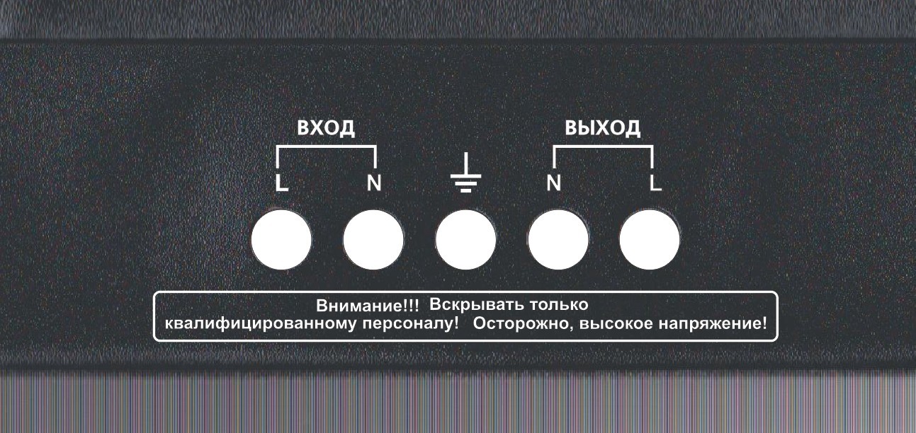
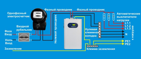
Pay attention - in all phase stabilizers along the edges of the terminal block (left - input, right - output), zeros are closer to the center, and in the middle is the ground!
Such terminals are used for stabilizers with a power of more than 5 kW. For powers up to 5 kW, as a rule, an ordinary plug with grounding is used for connection, and sockets on the stabilizer housing are used to connect consumers.
Based on the selected resistor, the reference value can be set to zero volts; no additional feedback resistors are required. The 10mΩ external resistance only adds about 15mV of output power reduction to the 3A output. Even at output voltages up to 1V, this only adds 5% to the regulation. Series input resistors can further distribute heat if the input-output differential signal is large.
In this tutorial, we'll look at how to use a voltage regulator in a circuit! Voltage regulators are designed to maintain and stabilize voltage levels. Regulators are found in most electronic devices and can be used to turn off and control voltage outputs from a source. high voltage dissipating excess energy as heat. This is great for applications where you need multiple discrete voltages for different devices in the same circuit as you can use voltage regulators to output one higher output source!
For ease of understanding, I will give a typical input circuit of apartment wiring:
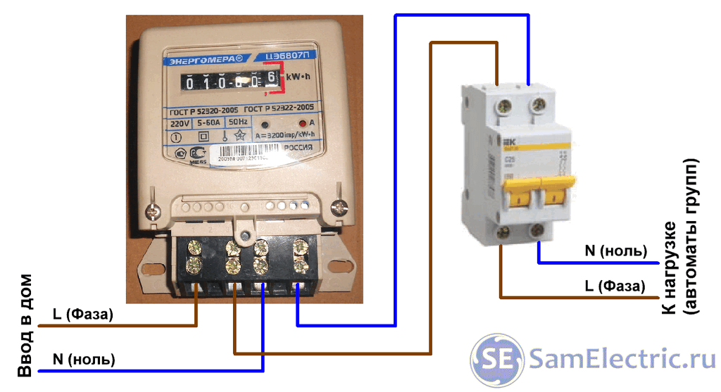
It is worth saying that the introductory (general, main) two-pole machine can stand both BEFORE the meter and after. Further, after the counter, there should be circuit breakers for groups of loads (sockets, lighting, etc.)
Maybe it will be interesting
Most voltage regulators have 3 pins. Input is the input voltage from the original source. For example, a battery or power supply. You feed the output of this device to the input of the regulator. The input should always be as clean as possible and should always be greater than the required output voltage. Most voltage regulators have a minimum specified input voltage, so make sure you stick to that.
Earth - required common land between input and output voltages. This must be connected to ground in the circuit and is required for the regulator to function. The output contact provides a regulated voltage. How to use voltage regulators in a circuit? How voltage regulators work is a subject in itself, so we won't go into detail here. Suffice it to say that voltage regulators are essentially voltage dissipators that convert excess voltage into heat.
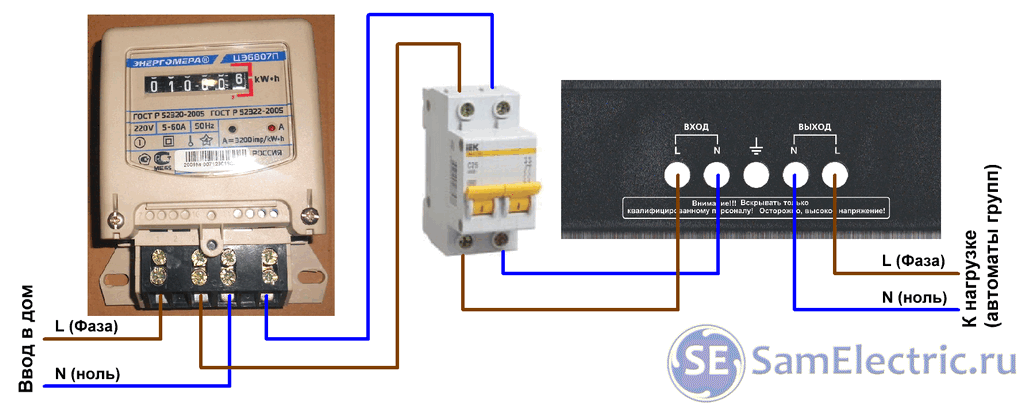
The stabilizer must be connected after the counter. And there should be a circuit breaker in front of the stabilizer, which will remove power from the stabilizer if necessary.
The wiring diagram with the stabilizer connected will be as follows:
A higher input voltage will result in a higher voltage regulator, it is complicated to get rid of this excess voltage, so users should be aware of this! There are a few things to be aware of when using voltage regulators in a circuit.
If there are more pins, make sure you know what they do and if extraneous components are required. Excess voltage is dissipated by the regulator as heat, so be careful when designing and using circuits. If you lower a lot of voltage, more heat will be generated by the regulator and you may need a heatsink to keep your regulator from burning out. If it's too hot, it's probably too hot! Most regulators only have 3 ports. . The generator has a centrally rotating set of coils fed from the field terminal.
I repeat - the circuit breaker can stand BEFORE and / or AFTER the counter, but always BEFORE the stabilizer.
The figure shows the connection diagram of SUNTEK voltage stabilizers.
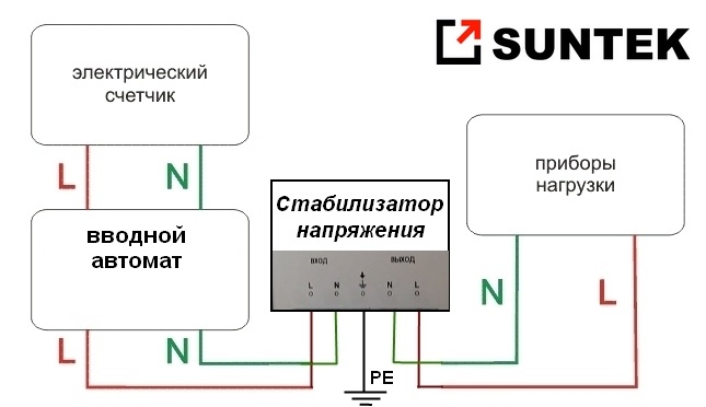
Scheme of connecting the stabilizer to a single-phase network
Indication on the scoreboard using the example of a Suntek voltage stabilizer
The indication of the status of operation or error is the same for many manufacturers.
As this rotor turns, it pulls the magnetic field past the stationary coils that surround it. The voltage output is determined by the amount of current in the field circuit and is controlled by a voltage regulator. Ground connection on generator frame alternating current terminates the electrical circuit.
Battery power comes from the starter solenoid connection. Power is supplied from the ignition switch through a fuse to the voltage regulator. Voltage is measured from this source. Internal circuits take the power supply and regulate it by sending it to the field terminal of the alternator so that the output voltage on the battery is correct.
During operation, the following information may appear on the display of the stabilizer:
Letter "H"
The appearance of the letter “H” (High) on the display means that the voltage in the network has risen above the operating range and the overvoltage protection has worked, the stabilizer turned off the output voltage to avoid damage to the load. When the input voltage returns to the operating range, the output voltage figure will reappear on the display and the stabilizer will automatically switch to the operating mode.
Incorrect loading or output problems can be caused by improper grounding of the regulator. The device can be connected to earth through its mounts or a separate cable. A low load can be caused by defective brushes on the alternator, slipping rings, or a bad regulator.
A simple way to check the alternator is to start the engine and connect a voltmeter across the battery terminals. If you are only reading battery voltage, it is due to a fault in the alternator, its wiring, or the isolation relay. If you register an excessive load, it is due to a violation of the regulator.
Maybe this will be interesting:
Letter "L"
The appearance of the letter "L" (Low) on the display means that the voltage in the network has dropped below the operating range and the protection against undervoltage, the stabilizer turned off the output voltage to avoid breaking the load. When the input voltage returns to the operating range, the output voltage will reappear on the display and the stabilizer will automatically switch to the operating mode.
Write down how many cables there are and where they are placed. Also positioning washers and slots. In most vehicles, you must turn off the alternator. Loosen the cables and remember where they are. Maybe two, three or four next to the metal connection tag. The regulator can be fixed with two screws or with a screw and mounting slots. Be aware of how these slots are placed to properly install a new device. Be careful not to lose screws or washers.
Some internal regulators have a connecting line running from one of the terminals to the regulator housing. You may need to loosen the mounting screw and move the link out of the way. A new one-disc advertisement cannot be identical in all its aspects to the previous one. It may have more or less connecting cables.
Letters"C-H"
The appearance of the letters "C-H" (Current-Heat or Current-High) on the display means that the total power of the devices connected to the stabilizer has exceeded the rated power of the stabilizer and the thermal protection has tripped. You need to reduce the load. Further, the stabilizer itself will automatically switch to operating mode.
In the event that the voltage often goes beyond the permissible limits or a zero break is possible, the Barrier or PH type should be used.
Replacing an Independent Regulator
Follow the manufacturer's instructions carefully. They will tell you how to connect the device to different types generators. Reassemble the alternator, reconnect the battery, start the engine and check it. Replacing an independent regulator outside of the alternator is simple, whether it be a modern transistor or the electromagnetic transistor found in some imported cars.
Disconnect the regulator connections with the battery disconnected. Label the cables so you don't confuse them. Clean the area behind it to ensure good contact if it is connected to ground through its mounts. Place the new unit, reconnect the cables and then the battery.
And it is best to protect yourself from phase imbalance with the help of a voltage relay, which you can buy at an electrical engineering store, or on the Internet, for example here.
A real example of connecting a stabilizer
Let me tell you straight away - this connection a few “bad” places, but I won’t talk about them, I’ll look at the attentiveness of my readers)
Typical separate electronic regulator. Although the trend is to develop an electronic regulator inside the alternator, some are still divided. Separate pilot lamp relay. An isolation relay that isolates the alternator from the battery when the ignition is off.
Indication on the scoreboard using the example of a Suntek voltage stabilizer
An electromagnetic voltage regulator is installed in some older generators. An old car may have a dynamo instead of a generator. The dynamo has an independent regulator and a control unit with three electromagnetic switches for current and voltage control. It also has a cutting system to prevent battery drain due to the dynamo.
Initially, we have a disk inductive counter, I wrote about this in an article about.
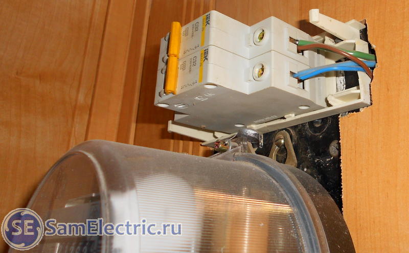
Home electricity meter, after the meter - two circuit breakers.
The upper automaton turns off the phase, the lower one - zero. One line goes to the house, the second - to the "summer" kitchen.
The case takes place in the private sector of Taganrog.
Some generators have separate solenoid controls. Others are a separate isolation relay. This is an electromagnetic switch that protects the generator when the ignition is off. Some vehicles have a separate control in the warning light circuit on the dashboard.
General information about the installation and operation of stabilizers
Individual components are usually installed in the engine bay or sometimes on top of the generator itself. The voltage regulator is an important component of your car's charging system. As the name suggests, it regulates the amount of voltage generated by the alternator to provide constant voltage on the battery and electrical equipment of your vehicle. The voltage of your alternator increases and decreases depending on the rotational speed of the alternator; too much voltage and the fuse blows if you don't have a regulator.
That is, the scheme corresponds to the one above.
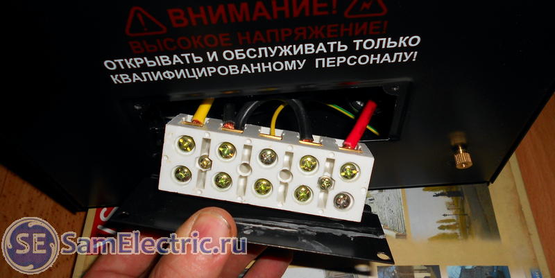
We open the terminal block of the stabilizer:
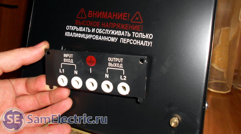
Rear panel of the stabilizer Energia SNVT-10000/1
I hope the bottom line is about me)))
As shown in the connection diagram above, we connect the stabilizer after the introductory machine. There is no other way, because the meter is connected to the street line directly!
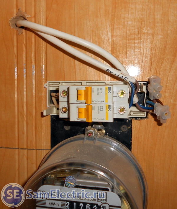
The stabilizer is installed behind the wall, so a hole (hole) was drilled, and 4 wires were laid through it by means of two PVS2x2.5 - phase to the stabilizer, zero to the stabilizer, zero to the house, phase to the house. The connection of these wires is shown in the photo at the beginning of this article.
When installing the stabilizer had to stand on all fours. No wonder I talked about the shelf at the beginning of the article!
We check the connection again (input-output, phase-zero), and turn it on:
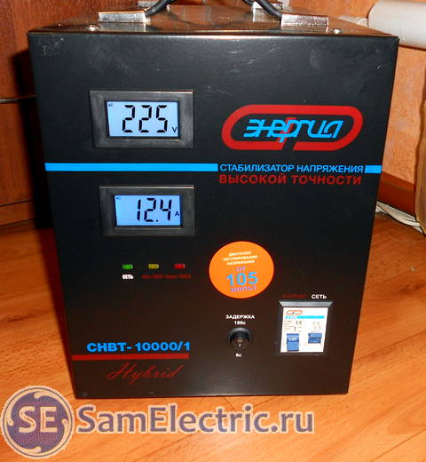
The displays show the output voltage and current.
I spread the instructions for the considered stabilizer. If you have read up to this point, it makes sense to look, quite informative: Download instructions for Stabilizers Energia SNVT.
Other stabilizers, instructions:
/ Passport for electromechanical stabilizers Suntek SNET-550, 1000, 1500, 2000, 3000, 5000, 8500, 11000 autotransformer type., pdf, 422.48 kB, downloaded: 535 times./
/ Operating manual for voltage stabilizers of electronic type (on a relay) SNET-550, 1000, 1500, 2000, 3000, 5000, 8500, 11000, pdf, 224.91 kB, downloaded: 547 times./
/ Guide to voltage stabilizers of the thyristor type SUNTEK TT (control on thyristor keys), pdf, 703.21 kB, downloaded: 444 times./
That's all, I ask readers with questions and constructive criticism in the comments!
If you want to purchase a stabilizer, . Low price, consultation, delivery (in Russia), installation (Taganrog).
Everyone knows that there are state standards by which goods are produced and services are provided. GOSTs did not bypass such a service as supplying voltage to residential buildings and industrial facilities. So, the standards strictly stipulate that the voltage can be supplied within certain limits, which are determined by the range of ± 10% of the rated voltage. And if we talk about single-phase voltage, where the nominal value is 220 V, then its difference varies between 198-242 volts. That is, it is the norm, which is fixed by the standards. But not all household appliances can work correctly at the minimum or maximum voltage from this range, so whether you like it or not, many ordinary people began to install voltage stabilizers. And here many people have the question of connecting it with their own hands, so the topic of our article is “voltage stabilizer - connection diagram”.
So, let's start with voltage drops, namely, for what reasons it occurs. If we consider the scheme for supplying electricity to houses, then from the substation it reaches each house through power lines. And the farther the house is from the substation, the lower the voltage reaches it. At the same time, the maximum indicator (242 V) is usually set at the substation. But if the load on some consumer increases, then at the end of the power transmission line the voltage is no longer up to the minimum allowable value (198 V). By the way, the three-phase line works in the same way.
This example shows a standard situation that worsens in winter time. But you can fix it, and there is only one option so far - this is connecting a voltage stabilizer to the electrical wiring diagram of an apartment or a private house.
The principle of operation of the stabilizer
In fact, this device stabilizes the input voltage to the nominal voltage that appears at the output. If we talk about operating modes, then there are three of them:
- Voltage drop;
- raising;
- Easy transmission without frequency change.
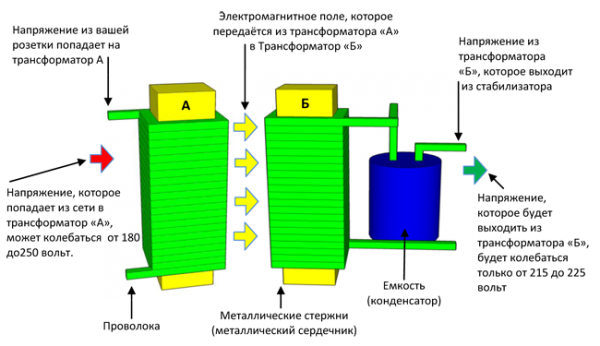
With the first two, everything is clear, but the third mode is practically useless, which leads to overheating of the stabilizer itself. And this is the main reason for its failure. Therefore, many manufacturers in the stabilizer circuit install a bypass-type circuit. If necessary, the switch directs the current through the bypass, bypassing the main circuit of the device.
If we talk about such a concept as a voltage stabilizer connection diagram, then first of all it is necessary to deal with the terminals of this device. There are several types of stabilizers, but there are two main modifications:
- The input and output have both phase and zero.
- The input and output has only a phase, zero is connected to the wiring directly.
Here is the diagram of the terminal connection itself:
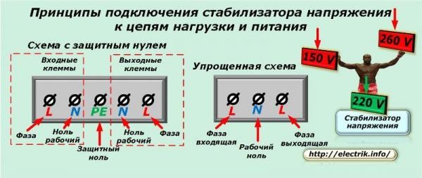
Attention! It can be clearly seen from the figure that the left half terminal box is the input, and the right one is the output. This is the standard terminal arrangement. Plus, if a zero circuit is also passed through the stabilizer, then the extreme terminals are designed to connect phases, the second from the edges to connect zero.
Manufacturers use this arrangement on purpose. It's like reading from left to right, so it's very easy to remember. For beginners, the terminals are indicated by letters.
Where is the best place to install a stabilizer
The installation location is selected depending on the dimensions of the device itself. And the dimensions depend on the power of the unit. For example, a low-power stabilizer can be installed right next to the equipment connected to it, somewhere on a table or on the floor. It is better to install a powerful device in a specially organized place, for example, in a niche or in a switchboard.
Installation requirements:
- The ventilation openings in the appliance must always remain free, not covered. During operation, the stabilizer heats up, so it always needs cooled air.
- Do not install voltage stabilizers in basements, garages, attics and similar rooms. The thing is that any electronic devices quickly fail if the rooms where they are installed have high humidity, dust accumulation, high temperature and other negative factors.
- The optimal installation location is in the very switchboard or nearby. The shorter the power cable, the better.
Wiring diagrams
It is necessary to single out a group of household appliances that really need a stable voltage. This group includes a TV, computer, refrigerator, radiotelephones. But those devices in which heating elements are installed, stable voltage is not required.
The most simple circuit connection is as follows - from the meter, the cable stretches to the RCD or differential automata, then a stabilizer is installed, from it the wires are already pulled to circuit breakers, which distribute the current into groups. The stabilizer is connected to the machine or machines that turn off a group of, so to speak, “gentle” household appliances.
Concerning three-phase network, then here you can install either a three-phase stabilizer, or three single-phase ones. The wiring diagram is the same for all. The only thing you need to pay attention to is the even distribution of the load on all three phases. If you deal with all the schemes, then connecting the stabilizer with your own hands will not be difficult.
How to choose the right voltage stabilizer
Currently, manufacturers offer three main types of stabilizers:
- Servo.
- Electronic.
The first option works on the principle of changing the number of turns on the device transformer. The change of turns is made by a special slider, which is powered by a servo motor. The device is quite simple, it is the cheapest device, but a large number of components and parts reduces its reliability. The most common causes of stabilizer failure are servo motor failure and abrasion of graphite brushes.
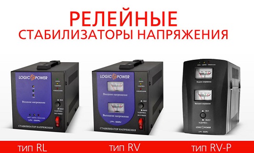
The relay voltage stabilizer is the middle segment in the stabilizer category. The design of devices of this type is based on a block of power relays. It is with their help that the transformer windings are switched. The advantage of relay stabilizers is their low price, the disadvantage is a short service life due to the presence of mechanical parts and assemblies in the design of the device. The main disadvantage is the sticking of the contacts in the relays themselves.
The electronic version is the most reliable and of the highest quality. Firstly, this is the complete absence of mechanical components. Secondly, all management is based on the presence electronic keys: triacs or thyristors. Such switching regulator voltage responds quickly, that is, it responds almost instantly within 20 ms to a change in the voltage in the network. Add to the positive qualities of the device its silent operation. This is especially a big plus if the stabilizer is in the room. But he has one minus - a high price.
An electronic-type voltage stabilizer built on microcircuits is the most popular today. Many consumers do not pay attention to the cost, because practice shows that stable and long-term operation is the main requirement.
Conclusion on the topic
Connecting a voltage stabilizer is directly related to its design, or rather, to the type of terminal box, and more precisely, to the number of input and output terminals. But if you need to connect one or two household appliances through the stabilizer, for example, a computer and a TV, then you can purchase the simplest option, plug it into an outlet through a wire with a plug, and connect the household appliances themselves to the output. If there is only one outlet, then you can additionally install a tee. But keep in mind that the power of the stabilizer should be slightly more than the total power of the devices connected to it.
Related posts:
We advise you to read
, diagnosis, treatment Treatment of urogenital chlamydia") Chlamydia urogenital - description, causes, symptoms (signs), diagnosis, treatment Treatment of urogenital chlamydia
Chlamydia urogenital - description, causes, symptoms (signs), diagnosis, treatment Treatment of urogenital chlamydia The benefits and significance of hydroamino acid threonine for the human body L threonine what
 To wait or not to wait for a guy from the army For what reason can they be commissioned from the army
 Baked apples with cottage cheese Baked apples with cottage cheese

