As far as schemes simple pulse converters constant voltage.
The main advantages of pulse converters:
Firstly, they have a high efficiency, and secondly, they can operate at an input voltage lower than the output.
Pulse converters are divided into groups:
- - step-down, step-up, inverting;
- - stabilized, unstabilized;
- – galvanically isolated, non-isolated;
- – with a narrow and wide range of input voltages.
For the manufacture of home-made pulse converters, it is best to use specialized integrated circuits - they are easier to assemble and not capricious when setting up.
Unstabilized transistor converter
This converter operates at a frequency of 50 kHz, galvanic isolation is provided by the T1 transformer, which is wound on a K10x6x4.5 ring made of 2000NM ferrite and contains: primary winding - 2x10 turns, secondary winding - 2x70 turns of PEV-0.2 wire. Transistors can be replaced with KT501B. The current from the battery, in the absence of load, is practically not consumed.

Stabilized transistor voltage converter
Transformer T1 is wound on a ferrite ring with a diameter of 7 mm, and contains two windings of 25 turns of wire PEV = 0.3.
Unstabilized voltage converter based on a multivibrator
Push-pull unstabilized converter based on a multivibrator (VT1 and VT2) and a power amplifier (VT3 and VT4). The output voltage is selected by the number of turns of the secondary winding of the pulse transformer T1.
Converter on a specialized chip MAX631
A stabilizing type converter based on a MAX631 chip from MAXIM. The generation frequency is 40 ... 50 kHz, the storage element is the L1 choke.
Unregulated two-stage voltage multiplier on the MAX660
You can use one of the two chips separately, for example the second, to multiply the voltage from two batteries.
Switching boost regulator on the MAX1674 chip
A typical circuit for switching on a switching boost stabilizer on a MAX1674 chip from MAXIM. Operation is maintained at an input voltage of 1.1 volts. Efficiency - 94%, load current - up to 200 mA.
MCP1252-33X50: Two voltages from one power supply
Allows you to receive two different stabilized voltages with an efficiency of 50 ... 60% and a load current of up to 150 mA in each channel. Capacitors C2 and C3 are energy storage devices.
Switching step-up stabilizer on the MAX1724EZK33 chip from MAXIM
A typical circuit for switching on a specialized microcircuit from MAXIM. Remains operational at an input voltage of 0.91 volts, has a small-sized SMD package and provides a load current of up to 150 mA with an efficiency of 90%.
Switching buck regulator on the TL497 chip
A typical circuit for switching on a switching buck regulator on a widely available TEXAS chip. Resistor R3 regulates the output voltage within + 2.8 ... + 5 volts. Resistor R1 sets the current short circuit, which is calculated by the formula: Ikz (A) \u003d 0.5 / R1 (Ohm)

Integrated voltage inverter on the ICL7660 chip
Integral voltage inverter, efficiency - 98%.
Two isolated converters based on DC-102 and DC-203 chips
Two isolated voltage converters DA1 and DA2, connected according to a “non-isolated” circuit with a common “ground”.

Bipolar stabilized voltage converter
Inductance primary winding transformer T1 - 22 μH, the ratio of turns of the primary winding to each secondary - 1: 2.5.
MAX734 stabilized boost converter
A typical scheme of a stabilized boost converter on a MAXIM chip.
Non-standard application of the MAX232 chip
This chip usually serves as an RS-232 driver. Voltage multiplication is obtained with a factor of 1.6 ... 1.8.
Chinese pulse market DC-DC converters pretty wide. And wandering around the expanses of the well-known AliExpress, I came across a small, cheap, but at the same time quite powerful converter. It should be said right away that for communication purposes, it, like any pulse converter, is limited, but nevertheless deserves close attention because of its size.
Earlier, I already wrote about various pulse converters that you can use for your projects.
But they all have relatively large dimensions and are not always convenient to use. The hero of this review is much more compact, but at the same time provides similar performance parameters. The converter board is supplied packed in an antistatic bag.

In appearance, the baby looks very frivolous, however, do not rush to conclusions.

The dimensions of the board are 22 x 17 mm. Compared to a 10 ruble coin.
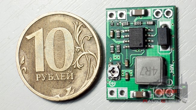
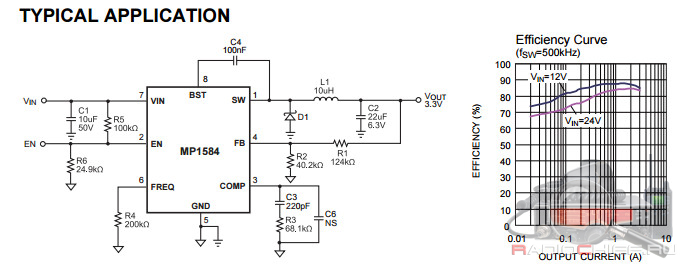
The converter is built on the basis of a specialized converter chip MP1584, the main features of which are:
- The input voltage can vary from 4.5 to 28 volts.
- The output voltage is adjustable from 0.8 to 25 volts.
- Built-in FET provides operating current up to 3A
- The operating frequency is up to 1.5 MHz (this explains such small dimensions).
- Built-in overheating protection (when reaching 120 degrees Celsius, the converter turns off)
- Sufficiently low level of ripple at the input and output of the converter.
- Output short circuit protection.
Of the shortcomings, one can note the complete lack of protection against polarity reversal. And if you inadvertently mixed up the polarity, the MP1584 chip will explode with a bang (one of the converters died in the name of science). 🙂

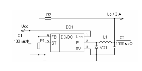
MP1584 wiring diagram from the datasheet. Actually, according to it, our converter is assembled. There is also a graph of efficiency depending on the current consumed.
Tests
To test the converter, we connect the M-Tech Legend III radio station to it,
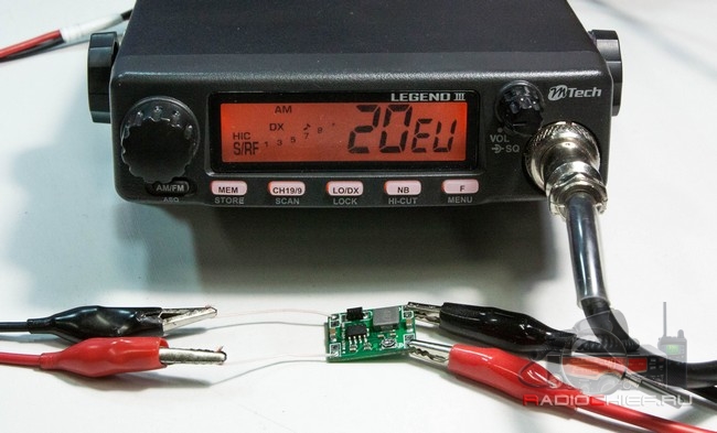
The converter itself is powered by an Atten PPS3005S laboratory power supply capable of delivering voltages up to 31 volts and current up to 5A. We will measure the current and voltage using a Vichy VC8145 multimeter.
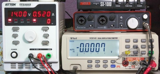
We will take the parameters before and after the converter.
The efficiency of the converter in terms of power is about 90%, which is just fine. 10% loss is quite an acceptable value. You also need to remember that the efficiency drops sharply when the input and output voltage spread is less than 3V (in the documentation, less than 5). So the efficiency of our baby is even higher than that of older brothers.
Let's measure the level of ripple at the input and output of the converter under a standard load in the form of an M-Tech Legend III radio station. We will investigate the signal at the input and at the output using an Atten ADS1102CAL oscilloscope. The main parameter under study is dV (pulsation amplitude between cursors CurA and CurB).
Ripple at the input (reception)
Output Ripple (Receive)
Input Ripple (Transmission)
Output ripple (transmission)
In comparison with similar, but more low-frequency converters, it looks quite good.
Temperature regime
We examine the converter for heating during operation.
Standby mode, current consumption 294mA

After 1 minute of transmission, the current consumption is 1.55A.
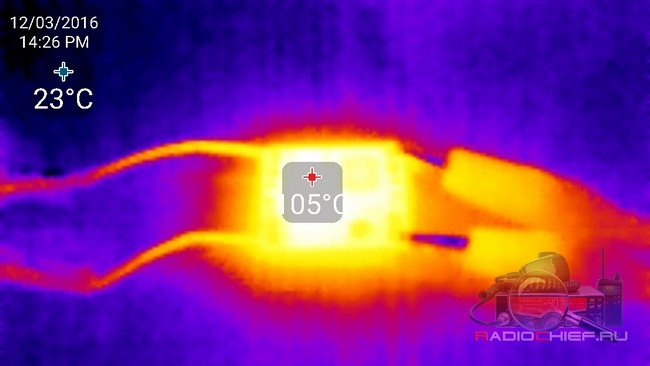
As you can see, the converter chip itself has heated up the most. Of course, our baby has a hard time, but in general, he passed the test.
Interference
The documentation for the MP1584 says: By switching at 1.5MHz, the MP1584 is able to prevent EMI (Electromagnetic Interference) noise problems, such as those found in AM radio and ADSL applications. What it means in translation: Since the conversion occurs at a frequency of 1.5 MHz, the MP1584 should not generate electromagnetic noise that causes problems when transceivers use amplitude modulation and ADSL technology. In my experience, the M-Tech Legend III radio, when connected through this converter, did not show any noticeable decrease in sensitivity. And yet, mindful of the principles of operation of pulse converters, I would not recommend using it to power sensitive communication equipment. The compact size of the transducer allows it to be placed even inside the station, but it is not known how much this will adversely affect the sensitivity of the receiver; additional studies should be carried out to verify this point.
Outcome
As a result, we have an excellent miniature converter that can be easily used to power various devices, for example, to build a power bank on a lead battery that will charge your mobile devices. Quite recently, I just had a similar kind of task, to power the equipment for shooting in the field, so as not to depend heavily on the batteries built into the equipment, and the converters on the MP1584 chip coped with this task perfectly.
K1224PN1x - an integrated circuit is a low DC to high AC converter and is used to control a flat fluorescent lamp. The voltage increase is carried out using an external inductance, on which high-voltage voltage pulses are generated at the frequency of the internal pump generator. The phase of the output voltage is controlled by the phase switching generator. The frequency of each generator is determined by the external capacitance. The IC contains: two self-oscillators forming the pump frequency and the switching period […]
The 1156EU1 chip is a set of functional elements designed to build a boost, step-down, or inverse type switching regulator. The device K1156EU1T is produced in a ceramic-metal case type 4112.16-3, and KR1156EU1 - in a plastic case type 283.16-2. FEATURES Designed for buck, boost and invert switching regulators Output voltage adjustment 1.25…40V Output impulse current………..<1,5А Входное напряжение ….2,5…40В […]
K1290EKxx, K1290EF1xx is a step-down switching voltage regulator for a load of up to 3A, designed to operate in the case temperature range of minus 10 ... + 85 ° C (K1290ExxP) and minus 60 ... + 125 ° C (K1290ExxX). Fixed output voltage: 3.3 V - K1290EK3.3 (A, B) P, K1290EK3.3X, 5 V - K1290EK5 (A, B) P, K1290EK5X, 12 V - K1290EK12 (A, B) P, 15 V - K1290EK15(A,B) FEATURES Programmable output voltage from 1.2 V to […]
Motorola's UA78S40 and National Semionductor's LM78S40 are ICs for general purpose switching converters. The UA78S40 (LM78S40) microcircuit allows you to create buck, boost and invert polarity pulse stabilized converters. The converter on the UA78S40 chip has a wide range of input and output voltage. Input voltage can vary from 2.5 to 40V, output voltage from 1.5 to 40V. Schottky diode 1N5822 in […]
The LM2576HV-ADJ Adjustable Switching Voltage Regulator (Blow-Down Pulse Width (PWM) Adjustable Voltage Regulator) has a wide adjustable output voltage range from 1.2V to 50V with a maximum output current of 3A. Since the stabilizer operates in a pulsed mode, it has a high efficiency and is usually equipped with a small radiator with an area of \u200b\u200bno more than 100 cm2. The device has thermal protection and […]
The figure shows a diagram of a simple voltage converter. The CD4047 IC operates in the unstable multivibrator mode, from the output of which, in antiphase, the signal goes to the IRFZ44 MOSFET transistors, the load of which is normal (a network transformer with windings connected vice versa, where the 220 winding becomes secondary) 60-100 W step-up transformer with primary winding 2 * 12V and a tap from the middle.
IC CAT3603 provides 30 mA per channel and operates with an input voltage of 3 ... 5.5V. The quiescent current consumption of the microcircuit is extremely small, 0.1 mA, which makes it possible to power it with a conventional battery. Operating conversion frequency 1MHz, converter efficiency 90%. There is a protection of the output from the short circuit. The output current of the microcircuit is regulated using the resistance R. The table shows the resistance values depending on […]

Frequency converters
Since the late 1960s, frequency converters have changed dramatically, mainly as a result of the development of microprocessor and semiconductor technologies, as well as due to their reduction in cost.
However, the fundamental principles underlying the frequency converters have remained the same.
The structure of frequency converters includes four main elements:
Rice. 1. Frequency converter block diagram
1. The rectifier generates a pulsating DC voltage when connected to a single/three-phase AC power supply. Rectifiers come in two main types - managed and unmanaged.
2. Intermediate chain of one of three types:
a) converting the rectifier voltage into direct current.
b) stabilizing or smoothing the ripple DC voltage and supplying it to the inverter.
c) converting the constant DC voltage of the rectifier into a varying AC voltage.
3. Inverter, which forms the frequency of the voltage of the electric motor. Some inverters can also convert a fixed DC voltage into a variable AC voltage.
4. An electronic control circuit that sends signals to the rectifier, intermediate circuit and inverter and receives signals from these elements. The construction of controlled elements depends on the design of a particular frequency converter (see Fig. 2.02).
Common to all frequency converters is that all control circuits control the semiconductor elements of the inverter. Frequency converters differ in the switching mode used to regulate the motor supply voltage.
On fig. 2, which shows the various principles of construction / control of the converter, the following notation is used:
1 - controlled rectifier,
2- uncontrolled rectifier,
3- intermediate circuit of the changing direct current,
4- Intermediate circuit of constant voltage DC
5- intermediate circuit of the changing direct current,
6- inverter with amplitude-pulse modulation (AIM)
7- inverter with pulse width modulation (PWM)
Current inverter (IT) (1+3+6)
Converter with amplitude-pulse modulation (AIM) (1+4+7) (2+5+7)
PWM converter (PWM/VVCplus) (2+4+7)

Rice. 2. Various principles of construction/control of frequency converters
For completeness, direct converters should be mentioned, which do not have an intermediate circuit. Such converters are used in the megawatt power range to form a low-frequency supply voltage directly from the 50 Hz mains, while their maximum output frequency is about 30 Hz.
Rectifier
The mains supply voltage is a three-phase or single-phase AC voltage with a fixed frequency (for example, 3x400V/50Hz or 1x240V/50Hz); the characteristics of these voltages are illustrated in the figure below.
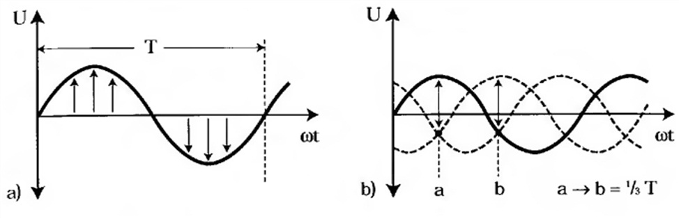
Rice. 3. Single-phase and three-phase AC voltage
In the figure, all three phases are shifted from each other in time, the phase voltage constantly changes direction, and the frequency indicates the number of periods per second. A frequency of 50 Hz means that there are 50 periods per second (50 x T), i.e. one period lasts 20 milliseconds.
The rectifier of the frequency converter is built either on diodes, or on thyristors, or on a combination of them. A rectifier built on diodes is uncontrolled, and on thyristors it is controlled. If both diodes and thyristors are used, the rectifier is semi-controlled.
Uncontrolled rectifiers
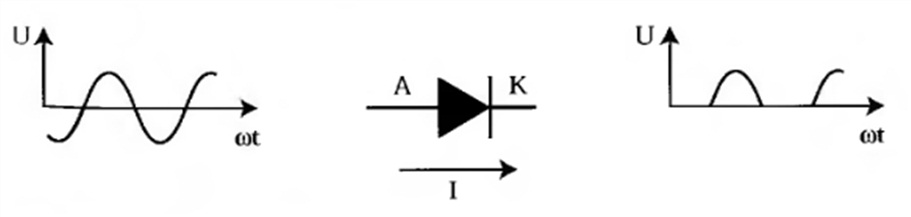
Rice. 4. Diode operation mode.
Diodes allow current to flow in only one direction: from the anode (A) to the cathode (K). As with some other semiconductor devices, the amount of diode current cannot be controlled. The AC voltage is converted by the diode into a pulsating DC voltage. If an uncontrolled three-phase rectifier is supplied with a three-phase AC voltage, then the DC voltage will also pulsate in this case.

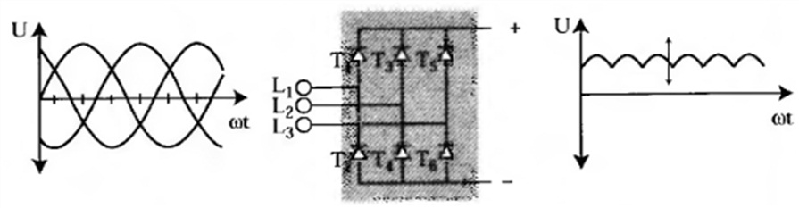
Rice. 5. Uncontrolled rectifier
On fig. 5 shows an uncontrolled three-phase rectifier containing two groups of diodes. One group consists of diodes D1, D3 and D5. Another group consists of diodes D2, D4 and D6. Each diode conducts current for a third of the cycle time (120°). In both groups, the diodes conduct current in a certain sequence. The periods during which both groups work are shifted between themselves by 1/6 of the time of the period T (60°).
Diodes D1,3,5 are open (conductive) when a positive voltage is applied to them. If the voltage of phase L reaches a positive peak value, then diode D is open and terminal A receives the voltage of phase L1 The other two diodes will be affected by reverse voltages of U L1-2 and U L1-3
The same happens in the group of diodes D2,4,6. In this case, terminal B receives a negative phase voltage. If at the moment the phase L3 reaches the limit negative value, the diode D6 is open (conducts). Both other diodes are affected by reverse voltages of U L3-1 and U L3-2
The output voltage of an uncontrolled rectifier is equal to the voltage difference between these two diode groups. The average value of the ripple DC voltage is 1.35 x mains voltage.
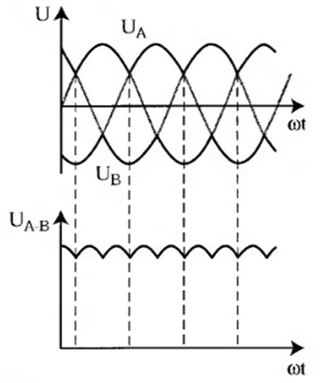
Rice. 6. Output voltage of uncontrolled three-phase rectifier
Controlled Rectifiers
In controlled rectifiers, diodes are replaced by thyristors. Like a diode, a thyristor passes current in only one direction - from the anode (A) to the cathode (K). However, in contrast to the diode, the thyristor has a third electrode called the "gate" (G). In order for the thyristor to open, a signal must be applied to the gate. If current flows through the thyristor, the thyristor will pass it until the current becomes zero.
The current cannot be interrupted by applying a signal to the gate. Thyristors are used in both rectifiers and inverters.
A control signal a is applied to the gate of the thyristor, which is characterized by a delay expressed in degrees. These degrees cause a delay between the moment the voltage passes through zero and the time when the thyristor is open.

Rice. 7. Thyristor operation mode
If the angle a is in the range from 0° to 90°, then the thyristor circuit is used as a rectifier, and if it is in the range from 90° to 300°, then as an inverter.
Rice. 8. Controlled three-phase rectifier
A controlled rectifier is fundamentally the same as an uncontrolled one, except that the thyristor is controlled by the a signal and begins to conduct from the moment when a conventional diode begins to conduct, until a moment that is 30 ° after the voltage zero crossing point.
Adjusting the value of a allows you to change the magnitude of the rectified voltage. The controlled rectifier generates a constant voltage, the average value of which is 1.35 x mains voltage x cos α
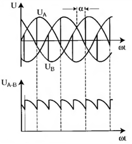
Rice. 9. Output voltage of controlled three-phase rectifier
Compared to an uncontrolled rectifier, a controlled rectifier has more significant losses and introduces higher noise into the power supply network, since with a shorter thyristor passing time, the rectifier draws more reactive current from the network.
The advantage of controlled rectifiers is their ability to return energy to the supply network.
Intermediate chain
The intermediate circuit can be considered as a storage from which the electric motor can receive energy through the inverter. Depending on the rectifier and inverter, there are three possible intermediate circuit design principles.
Inverters - current sources (1-converters)
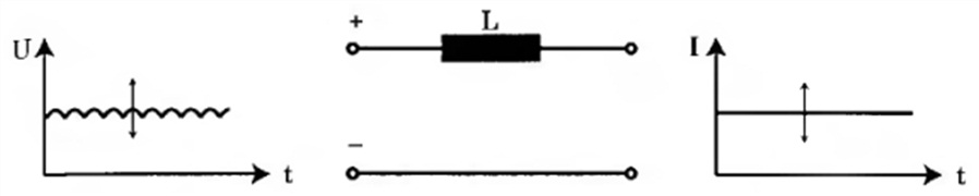
Rice. 10. Intermediate circuit of variable direct current
In the case of inverters - current sources, the intermediate circuit contains a large inductance coil and is mated only with a controlled rectifier. The inductor converts the changing rectifier voltage into a changing DC current. The motor voltage is determined by the load.
Inverters - voltage sources (U-converters)

Rice. 11. Intermediate DC voltage circuit
In the case of voltage source inverters, the intermediate circuit is a filter containing a capacitor and can be coupled to any of the two types of rectifier. The filter smoothes the pulsating DC voltage (U21) of the rectifier.
In a controlled rectifier, the voltage at a given frequency is constant and is supplied to the inverter as a true constant voltage (U22) with varying amplitude.
In uncontrolled rectifiers, the voltage at the input of the inverter is a constant voltage with a constant amplitude.
Intermediate circuit of variable DC voltage
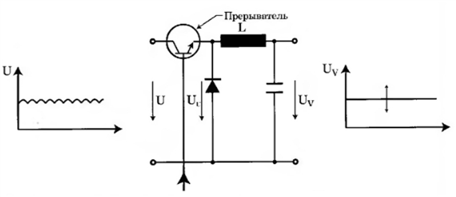
Rice. 12. Intermediate circuit of varying voltage
In intermediate circuits of varying direct voltage, it is possible to turn on a chopper in front of the filter, as shown in fig. 12.
The breaker contains a transistor that acts as a switch, turning the rectifier voltage on and off. The control system controls the chopper by comparing the changing voltage after the filter (U v) with the input signal. If there is a difference, the ratio is adjusted by changing the time the transistor is on and the time it is off. This changes the effective value and the magnitude of the constant voltage, which can be expressed by the formula
U v \u003d U x t on / (t on + t off)
When the interrupter transistor opens the current circuit, the filter inductor makes the voltage across the transistor infinitely large. To avoid this, the breaker is protected by a fast switching diode. When the transistor opens and closes, as shown in Fig. 13, the voltage will be the highest in mode 2.
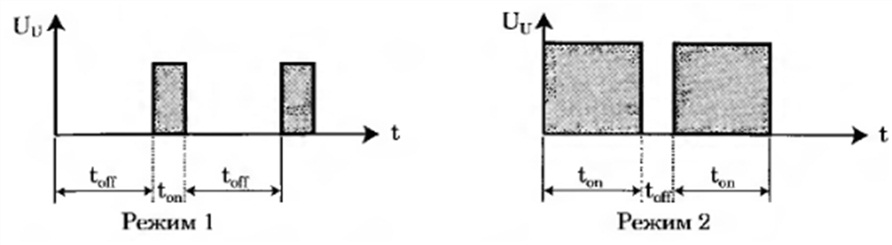
Rice. 13. The transistor-breaker controls the voltage of the intermediate circuit
The intermediate circuit filter smoothes the square wave after the breaker. The filter capacitor and inductor keep the voltage constant at a given frequency.
Depending on the construction, the intermediate circuit may also perform additional functions, which include:
Decoupling the rectifier from the inverter
Reducing the level of harmonics
Energy storage to limit intermittent load surges.
inverter
The inverter is the last link in the frequency converter before the electric motor and the place where the final adaptation of the output voltage takes place.
The frequency converter provides normal operating conditions over the entire control range by adapting the output voltage to the load mode. This allows you to maintain optimal magnetization of the motor.
From the intermediate circuit, the inverter receives
variable direct current,
Varying DC voltage or
Constant DC voltage.
Thanks to the inverter, in each of these cases, a changing value is supplied to the electric motor. In other words, the desired frequency of the voltage supplied to the electric motor is always created in the inverter. If the current or voltage is variable, the inverter only generates the desired frequency. If the voltage is constant, the inverter creates both the desired frequency and the desired voltage for the motor.
Even if the inverters work in different ways, their basic structure is always the same. The main elements of inverters are controlled semiconductor devices connected in pairs in three branches.
At present, thyristors have in most cases been replaced by high-frequency transistors, which are able to open and close very quickly. The switching frequency is usually between 300 Hz and 20 kHz, depending on the semiconductors used.
The semiconductor devices in the inverter are turned on and off by signals generated by the control circuit. Signals can be generated in several different ways.
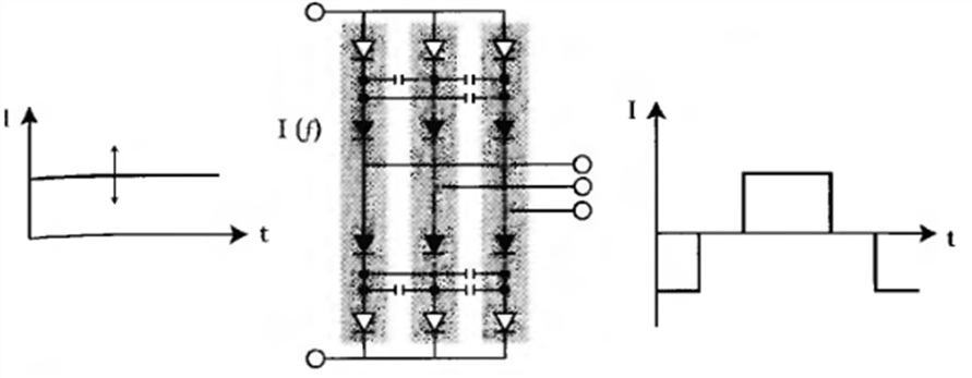
Rice. 14. Conventional intermediate circuit current inverter with variable voltage.
Conventional inverters, which mainly switch the intermediate circuit current of the changing voltage, contain six thyristors and six capacitors.
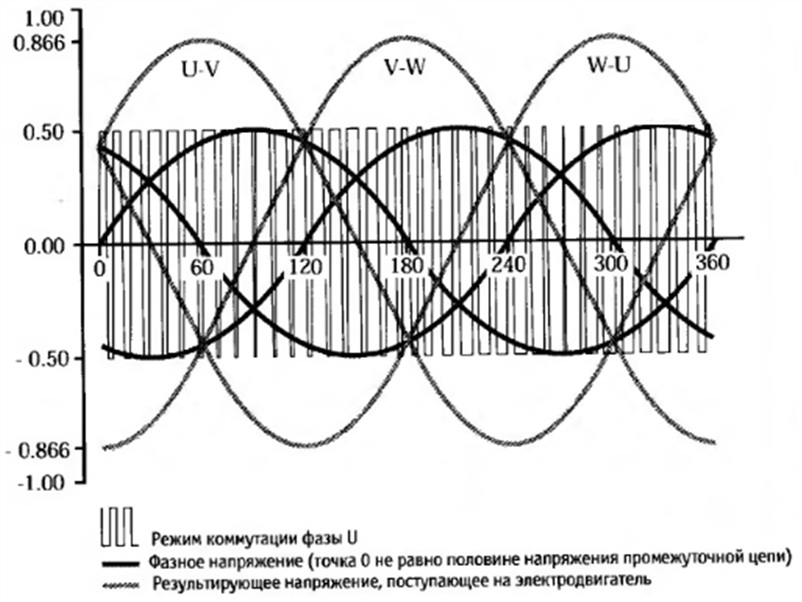
Capacitors allow thyristors to open and close in such a way that the current in the phase windings is shifted by 120 degrees and must be adapted to the motor size. When current is periodically applied to the motor terminals in the sequence U-V, V-W, W-U, U-V..., an intermittent rotating magnetic field of the required frequency is generated. Even if the motor current is almost square wave, the motor voltage will be almost sinusoidal. However, when the current is turned on or off, voltage surges always occur.
The capacitors are separated from the motor load current by diodes.
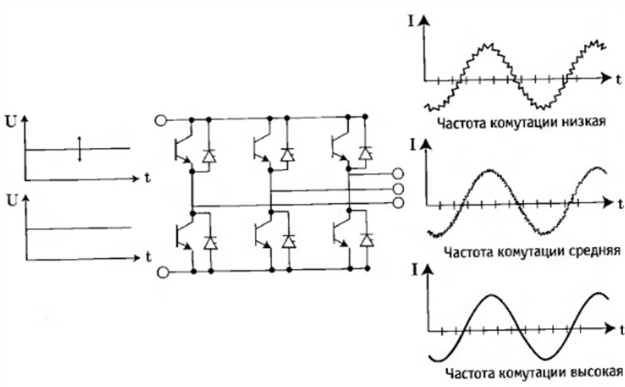
Rice. 15. Inverter for changing or constant intermediate circuit voltage and the dependence of the output current on the switching frequency of the inverter
Inverters with a variable or constant intermediate circuit voltage contain six switching elements and, regardless of the type of semiconductor devices used, work almost the same. The control circuit opens and closes the semiconductor devices using several different modulation methods, thereby changing the output frequency of the frequency converter.
The first method is for changing voltage or current in the intermediate circuit.
The intervals during which the individual semiconductors are open are arranged in a sequence used to obtain the desired output frequency.
This switching sequence of semiconductor devices is controlled by the magnitude of the changing voltage or current of the intermediate circuit. Through the use of a voltage controlled oscillator, the frequency always follows the amplitude of the voltage. This type of inverter control is called pulse amplitude modulation (PAM).
For a fixed intermediate circuit voltage, another basic method is used. The motor voltage becomes variable by applying the intermediate circuit voltage to the motor windings for longer or shorter periods of time.
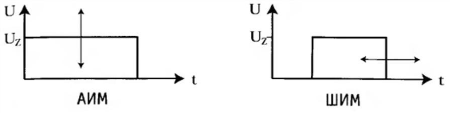
Rice. 16 Amplitude and pulse width modulation
The frequency is changed by changing the voltage pulses along the time axis - positively during one half-cycle and negatively during the other.
Since this method changes the duration (width) of voltage pulses, it is called pulse-width modulation (PWM). PWM modulation (and related methods such as sine-controlled PWM) is the most common way to drive an inverter.
With PWM modulation, the control circuit determines the switching times of the semiconductor devices at the intersection of the sawtooth voltage and the superimposed sinusoidal reference voltage (sinusoidally controlled PWM). Other promising PWM modulation methods are modified pulse width modulation methods such as WC and WC plus developed by Danfoss Corporation.
transistors
Since transistors can switch at high speeds, the electromagnetic interference that occurs when "pulsing" (motor magnetization) is reduced.
Another advantage of high switching frequency is the flexibility of modulating the output voltage of the frequency converter, which allows a sinusoidal motor current to be produced, while the control circuit only needs to open and close the inverter transistors.
The switching frequency of the inverter is a double-edged sword, since high frequencies can lead to motor heating and high voltage peaks. The higher the switching frequency, the higher the losses.
On the other hand, a low switching frequency can result in strong acoustic noise.
High-frequency transistors can be divided into three main groups:
Bipolar transistors (LTR)
Unipolar MOSFETs (MOS-FET)
Insulated Gate Bipolar Transistors (IGBTs)
IGBT transistors are currently the most widely used because they combine the driving properties of MOS-FET transistors with the output properties of LTR transistors; in addition, they have the right power range, suitable conductivity and switching frequency, which greatly simplifies the control of modern frequency converters.
In the case of IGBTs, both the inverter elements and the inverter controls are placed in a molded module called an "Intelligent Power Module" (IPM).
Pulse amplitude modulation (AIM)
Pulse-amplitude modulation is used for frequency converters with varying intermediate circuit voltage.
In frequency converters with uncontrolled rectifiers, the output voltage amplitude is formed by an intermediate circuit breaker, and if the rectifier is controlled, the amplitude is obtained directly.
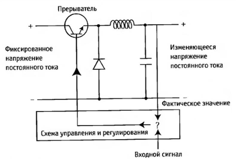
Rice. 20. Voltage generation in frequency converters with a breaker in the intermediate circuit
The transistor (breaker) in fig. 20 is unlocked or locked by the control and regulation circuit. The switching times depend on the nominal value (input signal) and the measured voltage signal (actual value). The actual value is measured across the capacitor.
The inductor and capacitor act as a filter that smooths out voltage ripples. The peak voltage depends on the opening time of the transistor, and if the nominal and actual values \u200b\u200bare different from each other, the breaker operates until the required voltage level is reached.
Frequency control
The frequency of the output voltage is changed by the inverter during the period, and the semiconductor switching devices operate many times during the period.
The duration of the period can be adjusted in two ways:
1.Directly input or
2.Using a variable DC voltage that is proportional to the input signal.

Rice. 21a. Frequency control with intermediate circuit voltage
Pulse Width Modulation is the most common way to generate a three-phase voltage with an appropriate frequency.
With pulse-width modulation, the formation of the total voltage of the intermediate circuit (≈ √2 x U mains) is determined by the duration and switching frequency of the power elements. The PWM pulse repetition rate between on and off is variable and allows for voltage regulation.
There are three main options for setting the switching modes in an inverter controlled by pulse-width modulation.
1. Sinusoidally controlled PWM
2. Synchronous PWM
3.Asynchronous PWM
Each branch of a three-phase PWM inverter can have two different states (on and off).
Three switches form eight possible switching combinations (2 3), and therefore eight digital voltage vectors at the output of the inverter or on the stator winding of the connected motor. As shown in fig. 21b, these vectors 100, 110, 010, 011, 001, 101 are at the corners of the circumscribed hexagon, using vectors 000 and 111 as zeros.
![]()
In the case of switching combinations 000 and 111, the same potential is created at all three output terminals of the inverter - either positive or negative with respect to the intermediate circuit (see Fig. 21c). For an electric motor, this means an effect close to a short circuit of the terminals; A voltage of 0 V is also applied to the motor windings.
Sinusoidally controlled PWM
With sinusoidally controlled PWM, a sinusoidal reference voltage (Us) is used to drive each inverter output. The duration of the period of the sinusoidal voltage corresponds to the required fundamental frequency of the output voltage. A sawtooth voltage (U D) is applied to the three reference voltages, see fig. 22.

Rice. 22. The principle of operation of a sinusoidally controlled PWM (with two reference voltages)
When the sawtooth voltage and the sinusoidal reference voltages cross, the semiconductor devices of the inverters either open or close.
The intersections are determined by the electronic elements of the control board. If the sawtooth voltage is greater than the sinusoidal voltage, then as the sawtooth voltage decreases, the output pulses change from positive to negative (or from negative to positive), so that the output voltage of the frequency converter is determined by the intermediate circuit voltage.
The output voltage is varied by the ratio between the duration of the open and closed state, and this ratio can be changed to obtain the required voltage. Thus, the amplitude of the negative and positive voltage pulses always corresponds to half the voltage of the intermediate circuit.
Rice. 23. Output voltage of sinusoidally controlled PWM
At low stator frequencies, the off time increases and can be so long that it is not possible to maintain the frequency of the sawtooth voltage.
This increases the period of no voltage, and the motor will run unevenly. To avoid this, at low frequencies, you can double the frequency of the sawtooth voltage.
The phase voltage at the output terminals of the frequency converter corresponds to half the intermediate circuit voltage divided by √2, i.e. equal to half the mains voltage. The line-to-line voltage at the output terminals is √3 times the line-to-line voltage, i.e. equal to the mains voltage multiplied by 0.866.
A PWM-controlled inverter that operates exclusively with a modulated sine-wave reference voltage can supply a voltage equal to 86.6% of the rated voltage (see Figure 23).
When using pure sine modulation, the output voltage of the frequency converter cannot reach the motor voltage because the output voltage will also be 13% lower.
However, the required additional voltage can be obtained by reducing the number of pulses when the frequency exceeds about 45 Hz, but this method has some disadvantages. In particular, it causes a step change in voltage, which leads to unstable operation of the electric motor. If the number of pulses decreases, the higher harmonics at the output of the frequency converter increase, which increases the losses in the motor.
Another way to solve this problem is to use other reference voltages instead of three sinusoidal ones. These stresses can be of any shape (for example, trapezoidal or stepped).
For example, one common voltage reference uses the third harmonic of a sinusoidal voltage reference. To obtain such a switching mode of semiconductor devices of the inverter, which will increase the output voltage of the frequency converter, it is possible by increasing the amplitude of the sinusoidal reference voltage by 15.5% and adding a third harmonic to it.
Synchronous PWM
The main difficulty in using the sinusoidally controlled PWM method is the need to determine the optimal values of the switching time and the angle for the voltage during a given period. These switching times must be set in such a way that only a minimum of higher harmonics is allowed. This switching mode is maintained only for a given (limited) frequency range. Operation outside this range requires the use of a different switching method.
Asynchronous PWM
The need for field orientation and system responsiveness in terms of torque and speed control of three-phase AC drives (including servo drives) requires a step change in the amplitude and angle of the inverter voltage. Using the “normal” or synchronous PWM switching mode does not allow stepping the amplitude and angle of the inverter voltage.
One way to meet this requirement is asynchronous PWM, where instead of synchronizing the output voltage modulation to the output frequency, as is usually done to reduce harmonics in a motor, the vector voltage control cycle is modulated, resulting in synchronous coupling with the output frequency.
There are two main variants of asynchronous PWM:
SFAVM (Stator Flow-oriented Asynchronous Vector Modulation = (synchronous vector modulation oriented to the stator flux)
60° AVM (Asynchronous Vector Modulation = asynchronous vector modulation).
SFAVM is a space-vector modulation method that allows the voltage, amplitude and angle of the inverter to change randomly but stepwise during the commutation time. This achieves increased dynamic properties.
The main purpose of using this modulation is to optimize the stator flux using the stator voltage while reducing the torque ripple, since the angle deviation depends on the switching sequence and can cause an increase in torque ripple. Therefore, the commutation sequence must be calculated in such a way as to minimize vector angle deviation. Switching between voltage vectors is based on the calculation of the desired magnetic flux path in the motor stator, which in turn determines the torque.
The disadvantage of the previous, conventional PWM power systems was the deviation of the amplitude of the stator magnetic flux vector and the magnetic flux angle. These deviations adversely affected the rotating field (torque) in the motor air gap and caused torque ripple. The influence of the U amplitude deviation is negligible and can be further reduced by increasing the switching frequency.
Motor voltage generation
Stable operation corresponds to the regulation of the voltage vector of the machine U wt so that it describes a circle (see Fig. 24).
The voltage vector is characterized by the magnitude of the voltage of the electric motor and the speed of rotation, which corresponds to the operating frequency at the considered point in time. The motor voltage is formed by creating average values using short pulses from neighboring vectors.
The Danfoss SFAVM method has the following features, among others:
The voltage vector can be adjusted in amplitude and phase without deviating from the set target.
The switching sequence always starts with 000 or 111. This allows the voltage vector to have three switching modes.
The average value of the voltage vector is obtained using short pulses of neighboring vectors, as well as zero vectors 000 and 111.
Control scheme
The control circuit, or control board, is the fourth main element of the frequency converter, which is designed to solve four important tasks:
Control of semiconductor elements of the frequency converter.
Communication between frequency converters and peripheral devices.
Data collection and generation of error messages.
Performing the functions of protecting the frequency converter and the electric motor.
Microprocessors have increased the speed of the control circuit, significantly expanded the scope of drives and reduced the number of necessary calculations.
The microprocessor is built into the frequency converter and is always able to determine the optimal pulse pattern for each operating state.
Control circuit for AIM frequency converter
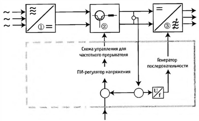
Rice. 25 Operating principle of the control circuit for an intermediate circuit controlled by a breaker.
On fig. 25 shows a frequency converter with AIM control and an intermediate circuit breaker. The control circuit controls the converter (2) and the inverter (3).
The control is based on the instantaneous value of the intermediate circuit voltage.
The intermediate circuit voltage drives a circuit that acts as a memory address counter for storing data. The memory stores the output sequences for the inverter's pulse pattern. When the intermediate circuit voltage is increased, the counting is faster, the sequence ends sooner, and the output frequency increases.
With regard to chopper control, the intermediate circuit voltage is first compared with the nominal value of the voltage reference signal. This voltage signal is expected to give the correct output voltage and frequency. If the reference signal and the intermediate circuit signal are changed, the PI controller informs the circuit that the cycle time needs to be changed. This causes the intermediate circuit voltage to adjust to the reference signal.
A common modulation method for controlling a frequency converter is pulse amplitude modulation (PAM). Pulse Width Modulation (PWM) is a more modern method.
Field control (vector control)
Vector control can be organized in several ways. The main difference between the methods are the criteria that are used when calculating the values of active current, magnetizing current (magnetic flux) and torque.
When comparing DC motors and three-phase asynchronous motors (Fig. 26), certain problems are identified. At direct current, the parameters that are important for generating torque - magnetic flux (F) and armature current - are fixed in relation to the size and location of the phase and are determined by the orientation of the excitation windings and the position of the carbon brushes (Fig. 26a).
In a DC motor, the armature current and the current that creates the magnetic flux are located at right angles to each other and their values are not very large. In an asynchronous electric motor, the position of the magnetic flux (F) and the rotor current (I,) depends on the load. Also, in contrast to a DC motor, phase angles and current cannot be directly determined from the size of the stator.

Rice. 26. Comparison of a DC machine and an AC induction machine
However, with the help of a mathematical model, it is possible to calculate the torque from the relationship between the magnetic flux and the stator current.
From the measured stator current (l s), a component (l w) is distinguished, which creates a torque with a magnetic flux (F) at right angles between these two variables (l c). This creates a magnetic flux of the electric motor (Fig. 27).
![]()
Rice. 27. Calculation of current components for field control
With these two current components, the torque and the magnetic flux can be independently influenced. However, due to the certain complexity of calculations based on the dynamic model of the electric motor, such calculations are cost-effective only in digital drives.
Because the load-independent excitation control is separated from the torque control in this method, it is possible to dynamically control an induction motor in the same way as a DC motor - provided there is a feedback signal. This method of controlling a three-phase AC motor has the following advantages:
Good response to load changes
Accurate power control
Full torque at zero speed
The performance is comparable to that of DC drives.
V/f and flux vector control
In recent years, speed control systems for three-phase AC motors have been developed based on two different control principles:
normal V/f control, or SCALAR control, and flux vector control.
Both methods have their own advantages, depending on the specific drive performance (dynamics) and accuracy requirements.
V/f control has a limited speed control range (approximately 1:20) and a different control principle (compensation) is required at low speed. Using this method, it is relatively easy to adapt the frequency converter to the motor, and the regulation is immune to instantaneous load changes over the entire speed range.
In flux controlled drives, the frequency converter must be precisely configured for the motor, which requires detailed knowledge of the motor parameters. Additional components are also needed to receive the feedback signal.
Some advantages of this type of control:
Fast response to speed changes and wide speed range
Better dynamic response to direction changes
A single control principle is provided over the entire speed range.
For the user, the best solution would be a combination of the best properties of both principles. Clearly, step load/unload stability over the entire speed range, which is usually a strong point of V/f control, and a fast response to speed reference changes (as in field control) are both required.
When designing electronic devices, a power supply with different output voltages is often required. DC-DC converters on switching capacitors are widely used in modern devices, making it possible to generate the required voltage from a single power source. The article discusses the principles of operation of such converters, their technical characteristics and applications.
Let's consider the principle of operation of the converter using the example of the widespread ICL7660 / MAX1044 microcircuit with extended functionality. The MAX1044 chip differs from the ICL7660 in the presence of the Boost input (increasing the frequency of the internal oscillator). The block diagram of the ICL7660 chip is shown in Fig. 1.
The circuit contains four power MOS switches controlled by logic elements and a voltage level shifter, which operate at a frequency obtained by dividing by two the frequency of the master RC oscillator. This allows you to generate control pulses with the required "meander" characteristics and optimize the consumption of the master RC oscillator, the operating frequency of which without external elements is 10 kHz. An internal voltage regulator is necessary to ensure the operation of the microcircuit from a source with reduced voltage.
The principle of operation of the microcircuit in the mode of an ideal voltage inverter will be considered according to the functional diagram shown in Fig. 2.
When the keys S1 and S3 are closed and the keys S2 and S4 are opened during the first half of the cycle, the external capacitor C1 is charged from the power source to the voltage V +, and when the keys S2 and S4 are closed and the keys S1 and S3 are opened during the second half of the cycle, the capacitor C1 transmits partially its charge to the external capacitor C2, providing a voltage -V + at the V OUT pin of the microcircuit. The specified voltage values correspond to the steady state.
The energy transferred by the capacitor C1 in one cycle is determined using the expression
![]() (1)
(1)
One of the main indicators of the converter is the conversion factor
![]() (2)
(2)
where U out - voltage at the output of the converter at a load current equal to i; U out.id. - voltage at the output of an ideal converter (for an inverter U out.id. = -U in).
From expression (2) it can be seen that a high value of the conversion coefficient is achieved when U out(i) = U out.id. , i.e. at V1 = V2. However, as can be seen from expression (1), in this case, the energy transferred by the capacitor C1 decreases, which makes it difficult to ensure a high value of the conversion coefficient. An increase in the energy transferred by the capacitor is possible by increasing the capacitance C1 or the operating frequency. In the first case, the dimensions of the capacitor increase and, consequently, the dimensions of the converter. In the second case, energy losses increase in a real device, which reduces its efficiency.
where P out is the power delivered to the load; Pin - power consumed from the power source.
It can be seen from the analysis that when developing a specific conversion device, it is necessary to optimize the values of the operating frequency and capacitance of capacitor C1. To do this, it is necessary to provide for the possibility of changing the operating frequency in accordance with the values of operating voltages and consumed currents.
Consider the electrical characteristics of the ICL7660 microcircuit, included according to the test circuit shown in Fig. 3.

Table 1. Brief electrical characteristics of the microcircuit at V + \u003d 5V, C OSC \u003d 0
Typical dependences of the electrical characteristics of the ICL7660 chip are shown in Fig. 4-8.
The given dependences allow to refine the parameters of the converter for specific values of operating voltages and consumed currents.
Let's consider typical circuits for switching on the ICL7660 chip.
voltage inverter
The circuit for switching on the microcircuit in the voltage inverter mode is shown in Fig. 9.

The inverter provides a voltage output V OUT equal to -V + in the range of 1.5V
The output impedance of the microcircuit depends on the DC mode and on the reactance of the capacitor C1.
![]() (3)
(3)
So, for the nominal C1 \u003d 10 microfarads and the frequency f \u003d 10 kHz X C \u003d 3.18 Ohm. To eliminate the effect of capacitor C1 on the output impedance, it is necessary that X C
To operate the microcircuit in the range of 1.5V
Reduced output impedance
To reduce the output resistance, you can apply the parallel connection of microcircuits, which is shown in Fig. 10.
The output impedance of such a circuit depends on the number of microcircuits connected in parallel. n and is defined using an expression.
![]() (4)
(4)
The figure shows that the capacitor C1 is individual for each microcircuit, and the capacitor C2 is common. The considered inclusion of microcircuits allows to increase the output current, the conversion factor and the efficiency of the converter.
Chip cascading
To increase the output voltage, you can use the cascading of microcircuits, shown in Fig. 11.
The output voltage of such a converter is -nV +. Given the allowable range of 1.5V
Voltage doublers
To obtain a positive voltage from a negative voltage source, as well as doubling the voltage, the microcircuit is turned on, shown in Fig. 12.
At pins 8 and 3, a voltage is generated V OUT \u003d -V -, and at pins 8 and 5 V OUT \u003d -2V -. The diode is necessary to ensure the initial stage of operation of the microcircuit. In some cases, it is convenient to use the switching circuit shown in Fig. 13.
The output voltage of such a converter is 2V + -2V F, where V F is the voltage drop across the diode in the forward direction (for silicon diodes V F \u003d 0.5-0.7V).
Voltage dividers
Using the ICL7660 chip, you can get a powerful voltage divider when you turn it on, as shown in Fig.14.
Combined voltage sources
The ICL7660 chip allows you to receive voltages with different ratings. One of the switching options is shown in Fig.15.
In the voltage converter shown in the figure, voltages - (V + -V F) and 2V + -2V F are formed.
Buffer operation
As can be seen from the material discussed above, converters with switched capacitors have reversible properties. This allows you to implement the buffer mode of their operation, one of the options for which is shown in Fig.16.

The device is powered from the source V IN , which provides the voltage V OUT (5th output of the n-th microcircuit) and V + (8th output of the first microcircuit) - battery recharge voltage. When the supply voltage fails or the power supply is disconnected, the voltage V OUT will be generated from the battery voltage V + .
Changing the frequency of the ICL7660 generator
The parameters of the considered converters depend on the frequency of the microcircuit generator. The dependence of efficiency on frequency is shown in Fig.6.
It can be seen from the figure that with an output current of 1 mA, high efficiency is provided at frequencies below 1 kHz. At higher frequencies, losses in the generator and power switch control circuits reduce the overall efficiency. To achieve high efficiency in this particular case, it is necessary to reduce the operating frequency of the converter. The operating frequency can be reduced using an external oscillator or by connecting C OSC as shown in Fig.3.
A simpler method is to use an external capacitor, the capacitance of which can be determined from the graph shown in Fig. 8.
For the case considered above, the operating frequency equal to 1 kHz is achieved by connecting an external capacitor with a capacity of C OSC \u003d 100pF. When applying this method, it must be taken into account that with C OSC greater than 1000pF, the capacitance of capacitors C1 and C2 must be increased to 100 microfarads.
The considered method of changing the frequency of the generator is used in micropower devices to ensure a high efficiency of the converter.
In some cases, the operating frequency of the converter must be increased. In these cases it is possible to use C1 and C2 of smaller capacity and therefore smaller dimensions. It also reduces generator noise levels in audio systems. The easiest way to increase frequency is with the Boost pin on the MAX1044. When the key S1 is closed (Fig. 3), the operating frequency of the microcircuit increases by 6 times.
Low Power Mode
When operating in standby mode, it is necessary to reduce the power consumed by the converter. Some microcircuits have an SD input, with which you can reduce the current consumption to units of microamps. The low power mode can also be implemented using the OSC input. Options for implementing this mode when using conventional logic elements, logic elements with an open drain (collector), as well as those with a third state are shown in Fig.17.

Microcircuits of voltage converters on switched capacitors are produced by a number of companies: Maxim, National Semiconductor, Microchip, etc. These microcircuits have the same principle of operation and differ in their implemented functions, electrical parameters and design. The undoubted leader in this area is Maxim, which produces the widest range of converter microcircuits. Table 2 shows the characteristics of some of the chips manufactured by various companies.
Table 2. Brief characteristics of microcircuits.
| Chip type | Implemented features | Output current (mA) | Input voltage V IN (V) | Frequency (kHz) | Current consumption (μA) | Note |
| ICL7660 TC7660 LMC7660 | -(V IN) or 2(V IN) or ½(V IN) | 20 | 1.5÷10 | 10 | 250 | |
| MAX889 | (-2.5V) (-V IN) | 200 | 2.7÷5.5 | 2000 | 50000 | Built-in shutdown function |
| MAX1680 MAX1681 | -(V IN) or 2(V IN) | 125 | 2÷5.5 | 125÷200 500÷1000 | 30000 | |
| MAX680 | 2(VIN) and -2(VIN) | 10 | 2÷6 | 8 | 1000 | |
| MAX681 | 2(VIN) and -2(VIN) | 10 | 2÷6 | 8 | 1000 | Without external capacitors |
| MAX1673 | 3B | 125 | 2÷5.5 | 350 | 16000 | |
| LM3350 | 3/2(V IN) or 2/3(VIN) | 50 | 1.5÷5.5 | 1600 | ||
| LM3352 | 2.5V; 3V or 3.3V | 200 | 2.5÷5.5 | 1000 | ||
| MAX870 | -(V IN) or 2(V IN) or ½(V IN) | 50 | 1.6÷5.5 | 56÷194 | 1000 | |
| MAX864 | 2(VIN) and -2(VIN) | 100 | 1.75÷6 | 7÷185 | 5000 | Built-in shutdown function |
Note: microcircuits MAX, ICL - firms MAXIM; LM, LMC - National Semiconductor; TC - Microchip.
The table shows that the converters on switched capacitors can operate in the modes of an inverter, a doubler, a divider of the input voltage by two, and allow you to generate several voltages at the output at the same time. Some microcircuits have built-in voltage regulators. The considered microcircuits are widely used in laptops, mobile phones, pagers, portable devices and other devices. In amateur radio practice, they can be used, for example, to generate bipolar supply voltages for operational amplifiers, to provide buffer power to electronic devices from a single battery cell, to generate an LCD supply voltage, etc. Small dimensions, high conversion factor and efficiency, absence of inductances, reversible properties are very attractive for the use of the considered converters in the development of various electronic devices.
Literature
- Maxim full-line CD-Catalog Version 5.0 2001 Edition.
- National Analog and interface products databook, 2001 Edition.


