The operation of pumping equipment in the autonomous water supply system is regulated by special automation. One of the main parts that control network parameters is a pressure switch. This device is factory set to a low and high limit at which the pump will turn on. If it is necessary to change the indicators, the pressure switch of the pumping station is adjusted. Such an operation does not require the involvement of specialists, knowing the settings rules, it can be carried out independently.
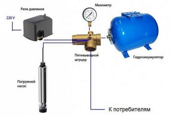
Water supply network with relay
How the pressure switch works
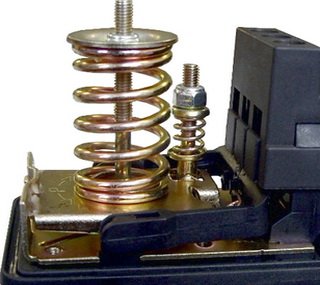
Regardless of the manufacturer, the water pressure switch in the water supply system is a compact unit with two springs and electrical contacts. The hydraulic part of the device is a membrane with a piston and two springs. different sizes. The electrical part is a contact group, opening / closing network for turning the pump on / off. All structural parts, including the terminal block, are attached to the metal base. The device has several terminal groups:
- for connecting voltage 220V;
- for grounding;
- terminals for the pump.
On the back side there is a nut for connecting to the fitting. From above, the device is covered with a plastic cover, fixed to the screw of a larger spring. Products from different factories can be equipped additional elements, have a characteristic shape and arrangement of nodes, but they all have a similar design. The sensor can be mechanical or electronic. Mechanical devices are more popular due to their low cost.
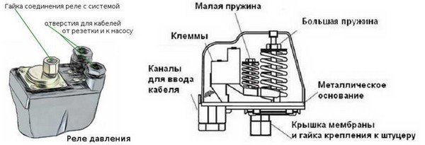 Relay design
Attention. A screwdriver or wrench is required to remove the plastic cover from the instrument.
The principle of operation of the relay
The pressure switch device of the pumping station does not require human intervention in the process of turning the pump on and off. The principle of its operation is based on changing the degree of impact on the piston responsible for closing the contacts. A large spring mounted on a stem with an adjustment nut counteracts the movement of the diaphragm and piston. When the pressure in the system decreases due to water parsing, the contact platform lowers and closes the contacts. The pump turns on and begins to pump fluid.
 Mechanical pressure controller
The flow of water into the accumulator leads to an increase in air pressure on the membrane of the device. The piston, overcoming the action of the spring, begins to displace the contact platform. This process causes the electrical contacts to open. The current is turned off not immediately, but when the platform is retracted to a distance determined by the setting of the small spring. This regulator is responsible for the pressure difference. After the contacts are completely open, the unit stops pumping water.
Information. A large spring is used to adjust the lower pressure level (on), a small spring is used to set the upper limit (off).
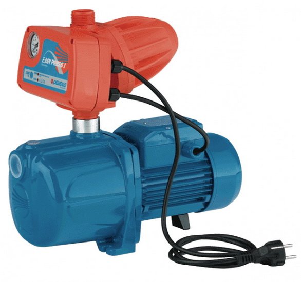
Preparation of the pumping station
When organizing individual water supply, special equipment is installed - a pumping station. It consists of two parts:
- submersible (surface) pump;
- hydraulic accumulator.
Read also:
All about the Gileks pumping station: model range, marking, design features and malfunctions
A sealed tank with a rubber membrane installed inside serves to store a supply of water and maintain a stable pressure in the system. Before you start setting up the pressure switch of the pumping station with your own hands, you should prepare the tank. The tank consists of a rubber pear into which water is pumped, and a chamber filled with air. The magnitude of the air pressure affects the operation of the entire water supply system, so it is necessary to set up a pumping station.
The preparation of the membrane tank begins with the complete draining of water from the pipeline and the tank itself. For this, the bottom tap of the system is used. Air is injected into an empty tank, its pressure must be less than the lower limit by 10%. The minimum pressure value is determined depending on the size of the accumulator:
- 20-30 l - 1.4-1.7 bar;
- 50-100 l - 1.8-1.9 bar.
After determining the pressure in the storage tank, the system is immediately filled with water; the rubber bulb must not be allowed to dry out.
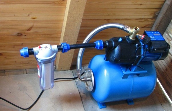 Pumping station with hydraulic accumulator and sensor
Attention. Self-checking the pressure in the tank is necessary when assembling equipment from individual parts. Modern models of pumping stations, manufactured in the factory, have ready-made settings specified in the documents.
For the tank membrane to last long term, it is recommended to set the pressure in the accumulator to 0.1-0.2 atm. lower than the minimum level in the system.
Where to install a mechanical controller?
When choosing a place to connect the pressure switch to a submersible pump, possible turbulence and pressure surges should be avoided. The best option is to install near the accumulator. The operating conditions of the device should be taken into account; in the documents, the manufacturer indicates the permissible parameters of temperature and humidity. With a moisture-proof version of the sensor, you can install it together with the storage in the caisson. In order for the controller to start functioning, it must be connected to the electrical and water supply network.
For the relay, it is desirable to allocate a separate electrical line, but this condition is not required. A cable with a cross section of 2.5 mm 2 is laid from the shield. For safety, it is recommended to install a circuit breaker, with parameters corresponding to the characteristics of the pump. The device must be earthed.
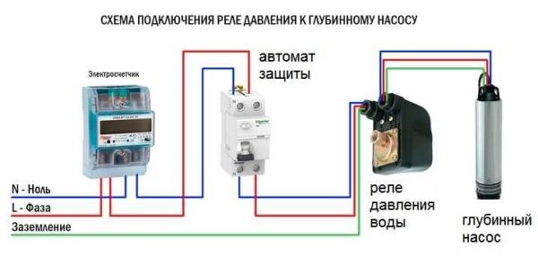 The terminal block has three groups of contacts: ground, phase and zero from the shield, wire from the pump.
 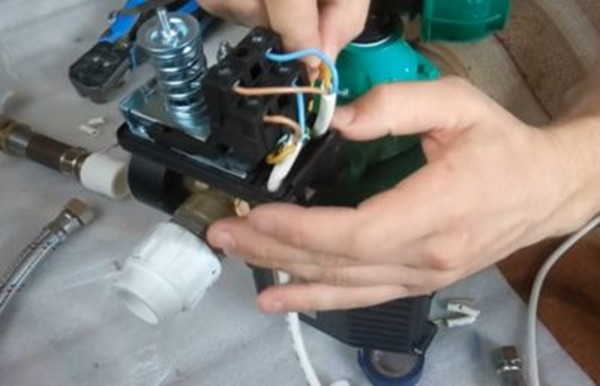 The connection is carried out as standard - the wire is stripped, inserted into the connector and fixed with a bolt
Attention. Connection to electrical network produced according to the inscriptions indicated on the contact group.
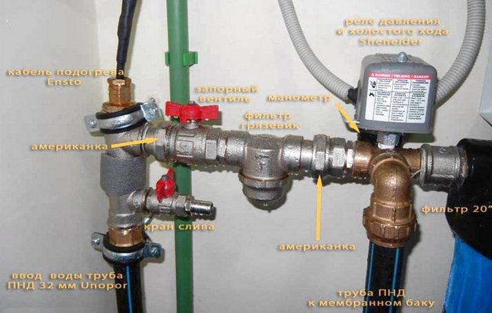
A submersible pump with a pressure switch can be connected using a tee or a five-way fitting. The connection is made through the nut on the back of the device. In the first case, the device is installed directly on the highway. The second option is preferable when a five-part assembly is assembled:
- Submersible or surface pump.
- Pressure gauge.
- Hydraulic accumulator.
- Pressure meter.
- Pipeline.
 Relay installation diagram
Advice. All threaded connections of the assembly need to be sealed; sealant or FUM tape is used for this purpose.
Mandatory elements of the water supply network at home are filters. These devices are necessary to purify the liquid from impurities that impair the operation of equipment, including pressure switches. After connecting the sensor to the water supply and the electrical network, all that remains is to adjust the pumping station with your own hands.
Read also:
Popular models of AL-KO pumping stations
Relay setting
The manufacturer provides the setting of pumping stations for average indicators:
- lower level - 1.5-1.8 bar;
- upper level - 2.4-3 bar.
Lower pressure threshold
If the consumer is not satisfied with such values, then knowing how to adjust the pressure in the pumping station, they can be changed. Having dealt with the installation of the correct pressure in the storage tank, proceed to adjust the sensor settings:
- The pump and relay are de-energized. All liquid is drained from the system. The pressure gauge is at zero at this point.
- The plastic cover of the sensor is removed with a screwdriver.
- Turn on the pump and record the pressure gauge readings at the time the equipment is turned off. This indicator is the upper pressure of the system.
- The tap farthest from the unit opens. The water gradually drains, the pump turns on again. At this point, the lower pressure is determined by the pressure gauge. The pressure difference to which the equipment is currently set is calculated mathematically - subtracting the results obtained.
Attention. To obtain the correct setting, you need a reliable pressure gauge whose readings can be trusted.
Having the opportunity to evaluate the pressure from the tap, select the required setting. Adjustment for increasing the pressure of the pumping station is carried out by tightening the nut on a large spring. If the pressure needs to be reduced, the nut is loosened. Do not forget that adjustment work is carried out after disconnecting the device from the power supply.
Attention. The setting is done carefully, the relay is a sensitive device. One turn of the nut changes the pressure by 0.6-0.8 atmospheres.
Upper pressure threshold
To set the optimal frequency of switching on the pump, it is necessary to adjust the pressure difference. A small spring is responsible for this parameter. The optimal value of the difference between the upper and lower pressure thresholds is 1.4 atm. If it is necessary to increase the upper limit at which the unit turns off, then the nut on the small spring is turned clockwise. When decreasing - in the opposite direction.
 Tuning scheme
What effect does this adjustment have on the equipment? An indicator below the average (1.4 atm.) Will provide a uniform supply of water, but the unit will often turn on and quickly break down. Exceeding the optimal value contributes to a gentle use of the pump, but the water supply will suffer due to noticeable pressure surges. Adjustment of the pressure difference of the pumping station is carried out smoothly and carefully. The impact needs to be verified. The scheme of actions performed when setting the lower pressure level is repeated:
- All appliances are disconnected from the mains.
- Water is drained from the system.
- The pumping equipment is turned on and the result of the adjustment is evaluated. In case of unsatisfactory performance, the procedure is repeated.
Read also:
Criteria for choosing a surface pump for a well
When making pressure difference adjustments, there are limitations that must be taken into account:
- Relay parameters. You can not set the upper pressure threshold equal to 80% of the maximum indicator of the device. Data on the pressure for which the controller is designed is present in the documents. Household models usually withstand up to 5 atm. If it is necessary to raise the pressure in the system above this level, it is worth buying a more powerful relay.
- Pump characteristics. Before choosing an adjustment, you must check the characteristics of the equipment. The unit must turn off at a pressure that is 0.2 atm. below its upper limit. In this case, it will function without overloads.
Features of adjustment "from scratch"
If both relay springs are weakened, the automation of the pumping station is adjusted according to the following algorithm:
- The unit is turned on to pump water into the system. The pressure level is controlled by observing the jet from a remote faucet. If the pressure is acceptable, then the pressure gauge reading is fixed, and the pump is turned off.
- Having disconnected the sensor from the network, open the cover and twist the nut of the large spring until the contacts close.
- The box is closed and the device is connected to the network again. The pump is turned on and left to work until the pressure on the pressure gauge reaches a mark equal to the previous value plus 1.4 atm.
- The unit and relay are disconnected from power, then tighten the nut on the smaller spring until the contacts open. The lower and upper threshold settings are now complete.
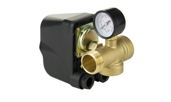 Pressure switch with pressure gauge
Using a sensor without a hydraulic accumulator
For some equipment models, a borehole pump connection scheme with a pressure switch without a storage tank is used. A special automatic controller starts and stops the unit when the limit values are reached. The electronic unit has the function of protection against "dry running" and ensures the safe operation of the system.
Attention. The disadvantage of such a scheme is the absence of a minimum supply of water, which is provided by a membrane tank.
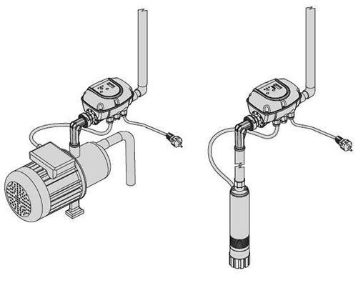 Electronic pressure switch for surface and submersible pump
Water pressure switch for pump Nowadays, it is widely used for water supply systems of a private house, cottage or other facilities where automatic water supply to the points of water intake is needed. Today, a water pressure switch is a necessary attribute for pumping equipment for an area where there is no centralized water supply system: personal plots, country houses, cottages, etc.
Today we will analyze the device and the principle of operation, specifications and pressure switch settings, consider the differences and their application, as well as the main malfunctions, their causes and repairs.
Application features and price
The water pressure switch is designed for use with electric water pumps with single-phase connection 220 Volts in the water supply system:
- pumping stations for water supply and hydraulic accumulator;
— centrifugal surface pumps;
— downhole pumps;
- submersible;
- submersible vibration pumps such as "Kid" or "Brook".
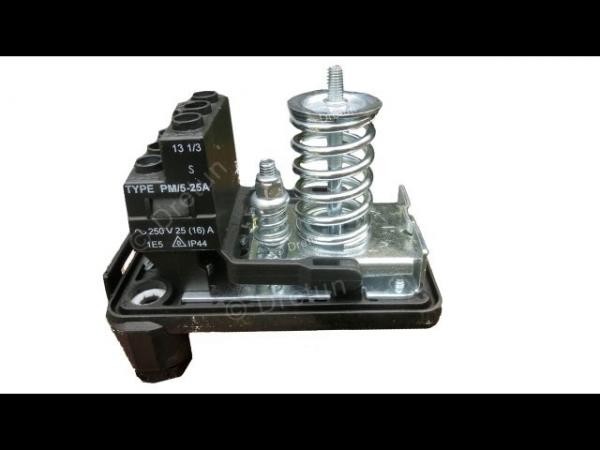
Pump pressure switch
As a rule, the pressure switch is already included in the package, and sometimes submersible pumps. In other cases, this device is purchased separately. The connection to the main line is made using a five-pin fitting. The relay is available either with an external thread (“male”) or with a nut with an internal thread (“mother”). The thread diameter is usually 1/4'.
It is worth noting that the price of a water pressure switch directly depends on the manufacturer, for example, a pressure switch made in Denmark "Grundfos" or Italy "Speroni" - from 1000-2000 rubles, and Chinese ones can be bought for 200-300 rubles. Russian "Dzhileks" RDM-5 or RD-5 - from 700 rubles. But, if you choose quality, then it is better to buy automation under a European brand.
In addition, the pressure switch may have a built-in pressure gauge, or it may be part of the pump automation unit in conjunction with a dry-running protection relay. Accordingly, this is also reflected in the price in the direction of its increase.
The device and principle of operation of the water pressure switch in the water supply system
The pressure switch consists of a plastic case, under which a membrane is “hidden”, which controls the operation of a normally closed group of contacts. This membrane is connected to the pressure line of the water supply system.
In the operation of the relay, there are such concepts as the pump on pressure and the pump off pressure. When buying a pressure switch, you must remember that this mechanism has a factory setting of the on and off parameters.
The pump turns on when the pressure threshold for turning it on in the water supply system (2.6 atm) is exceeded and turns off when the turn-off pressure drops (1.3 atm). As a rule, switching on occurs at 2.6 atm, and switching off - when the water pressure in the system drops to 1.3 atm, but these parameters can also be configured by hand.
In the photo and connection diagram, you can clearly see the pressure switch device for the pump.
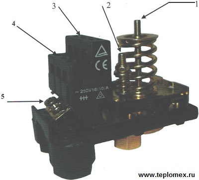
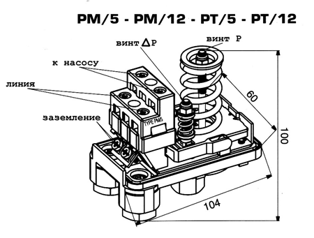
Water pressure switch device: connection diagram
1 - nut for adjusting the lower pressure limit;
2 - nut for adjusting the difference between the lower and upper pressure limits;
3 - terminals for connecting wires from the pump;
4 - terminals for connection to a single-phase electrical network;
5 - terminals for grounding.
In fact, a water pressure switch for a pump is a relay of a bundle of electrical circuits that has two contacts and responds to changes in pressure parameters in the water supply system. The pump pumps water while the contacts in the electrical circuit are closed, but when they open, the pump is powered off and it turns off.
The operation of the contacts in the electrical circuit directly depends on the set limits for the turn-on pressure and the turn-off pressure of the pump. After a certain period of time, these contacts may oxidize, requiring cleaning.
Setting the water pressure switch for the accumulator and pump
As we noted above, the relay initially has its own factory settings already set. But we can also configure the operation of this mechanism on our own to the values that are convenient for us. How to do it?
1. In order to increase the lower pressure limit, we need to turn the nut that regulates this limit clockwise (see diagram above) or counterclockwise to decrease this limit.
2. Both of these nuts have a mechanical effect on the pressure adjustment spring in the relay. With the help of the first, we set the lower limit, and the second - we set the necessary difference in pressure limits.
Specifications of the pressure switch
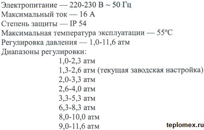
Relay specifications and settings
Malfunctions of the pressure switch for the pump and their solutions
1. The pump does not turn on.
It is necessary to check the presence of water in the suction section of the pipeline and the voltage in the mains. Turn off the power, then turn it back on after a while.
2. The pump frequently turns on and off.
Try lowering the shutdown pressure threshold, it may be too high.
3. The pump does not turn off.
Check the value of the maximum operating pressure of the pump. Normally, it should be 0.8 atmospheres higher than the switch-on pressure value. It is also worth checking the line for leaks and air accumulation in the water supply system.
Today we dismantled the device and the principle of operation water pressure switch for pump, its features, technical characteristics and application in everyday life. This is a convenient, modern and inexpensive mechanism that allows you to automate the operation of the entire plumbing system of a private house. Let's watch the video.
The pressure switch is a key element in the automation of the operation of a pump or pumping station, it gives a signal to turn the pump on and off. Depending on the manufacturer and model, the factory settings may differ, but, as a rule, the lower threshold for turning on the pump is set to a pressure of 1.4–1.8 bar, and the threshold for turning it off is 2.5–3 bar. But sometimes such threshold settings are insufficient for normal operation plumbing fixtures, so it is necessary to adjust the water pressure switch for the pump , to select individual options for turning it on and off.
Design and principle of operation
Before proceeding with setting up the relay, you need to understand the design and principle of its operation. The design of the relay is quite simple and consists of contacts spring-loaded by a plate on which water pressure acts.

- Frame.
- Contact group for connecting the pump.
- Terminals for connecting to the power supply.
- Ground terminals.
- Nut for connecting the relay to the water supply.
- Pressure differential adjustment spring.
- Minimum pressure adjustment spring.
- The node where the piston and the membrane are located.
On a metal base, a metal platform is fixed at one end, which can rise and fall under the action of a piston. The piston is driven by water pressure. Two springs (6.7) are installed on the platform, a large spring (7) counteracts the force of the piston (water), thereby balancing it. The small spring (7) does not come into action immediately, but after the platform has risen to a certain height, and as soon as the platform touches the smaller spring, the forces of both springs begin to oppose the piston and the resistance to the piston force increases, from this moment the platform needs to rise quite a bit, so that the contacts open and the pump turns off. A small hinge with a spring is responsible for opening and closing the contacts. As soon as the platform rises above this hinge, the contacts bounce down and electrical circuit opens as soon as the force of the piston (water) weakens, the platform goes down and the contacts close.
The large spring is responsible for turning on the pump, that is, for the lower pressure limit, and with the help of a small spring, the moment the pump is turned off is regulated, or rather, the difference between turning on and off is set.
Setting

Based on the principle of operation of the relay, its setting consists in changing the stiffness between the platform, which is affected by water pressure and the contacts. Adjustment is carried out by changing the stiffness of the spring, which is either compressed or weakened by adjusting nuts. Before starting the adjustment, it is necessary to fix the readings of the pressure gauge while turning the pump on and off. Next, disconnect the relay from the network, and remove the housing cover. Using a wrench, unscrewing or tightening the nuts, set the desired parameters:
- if it is only necessary to change the lower switching threshold (increase or decrease), then you need to press or loosen the nut on the spring (7);
- to increase or decrease the upper shutdown limit of the pump, you need to screw or unscrew the nut on the spring (6), when tightening - we raise the shutdown limit of the pump, and when unscrewing, on the contrary, we lower it, increasing the difference between switching on and off;
- if you need to change two parameters at once, then first the lower limit is adjusted using the spring (7), and then we set the difference using the spring (6);
All changes must be monitored with a pressure gauge. It is worth considering that by changing the pressure difference, we reduce or increase the duration of the pump, and this will be reflected in the change in pressure in the water supply network. If the pressure difference is small, then the pressure in the network will be “smooth” without visible drops, but the number of pump starts will increase, which may affect its service life.
When adjusting, you need to remember that the upper pressure should not be higher than the maximum pressure that the pump can create (it can be found in the pump's passport characteristics). The upper pressure must not exceed 80% of the maximum allowable pressure for a particular model, and these parameters are indicated in the instructions for the relay. Also, before setting up, you need to check the air pressure in the pear of the hydraulic tank - it should be less than the lower threshold for turning on the pump by 0.2 bar. Another requirement for adjustment is the difference between the on and off pressures, it must be in the range of 1–1.5 bar. When changing the parameters, do not tighten the nuts all the way, this can lead to the fact that the relay will stop working altogether.
Video
This video shows how to adjust the pressure switch for a pump:
Living in a city apartment, we do not know how the plumbing system of an apartment building works. Our task is to open the tap, and water will definitely come out of it under a certain pressure, sufficient and convenient for use. In private housing construction, everything is different, because you have to learn to understand all communication networks, and in the water supply too. And here you can not do without a pressure switch. So, the topic of this article: pressure switch RDM 5 - adjustment, instructions for use.
Why was this brand chosen? It's all about his high technical and performance characteristics. Judge for yourself:
- It works from a 220 volt network, and this is a great convenience, that is, you plug the plug into the outlet, and you don’t need to do anything else.
- Can be used at temperatures from 0C to +40C.
- Pressure range (working) from 1.0 atm. up to 4.6.
- At the factory, the relay itself is configured: the lower level is 1.4 atm., the upper level is 2.8 atm.
- The pressure drop is 1.0 atm. - This is the minimum.
- Degree of protection 1P 44.
- The internal size of the connected nozzles is ¼ inch. Installing the device with your own hands will be easy.
Principle of operation
So, the RDM 5 device is a two-contact relay used to switch the electrical network. It works only depending on the pressure of the water. Here is its working principle:
- The device is adjusted according to the lower and upper limits. If the water pressure in the pumping station at home is below the upper limit, then the contacts of the relay itself are closed, that is, current flows through its electrical circuit. So the pump itself is working.
- As soon as the water pressure in the system exceeds the upper limit, the relay is triggered to turn off the supply network, that is, its contacts open.

As you can see, the principle of operation of the pressure switch is quite simple. The main thing here is to accurately adjust the limits.
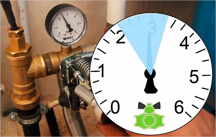
How to properly adjust
Often you come across such a position of installers that, they say, the set pressure of the relay at the factory is enough for the plumbing system to work comfortably and satisfy the requirements of the owner of the house. But, as life shows, moving into your own a private house, where a modern pumping station with a pressure switch is installed, the water pressure does not satisfy us (it is small). Asking a specialist to adjust the pressure in the system is useless (most often), so you should figure it out on your own.
So, the plumbing system at home most often consists of:
- Water intake point - this can be a village water pipe or a well with a submersible pump.
- Pressure switch with hydraulic accumulator.
- Water treatment in the form of a system of tanks and filters.
- Consumer.
How to properly adjust the pressure switch. Firstly, it is necessary to understand what pressure will be needed so that it is sufficient in the process of opening all points of consumption, especially for the soul, as the most powerful consumer. Secondly, it is necessary to know the pressure at the point of water intake. After all, how does the relay, and accordingly the pump. If the pressure at the intake point is below 1.4 atm, then the relay will not even turn on, that is, the pump will not work. This often happens if your private house is connected to the village water supply network, where the pressure most often does not rise above 1.0 atm.
If water is taken from a well or well using a pump, then the pressure in the home network will depend on technical parameters unit. In any case, not lower than 2.0 atm. That is, you don’t have to worry that the relay will not turn on, so you can safely adjust it.
How to set the lower pressure limit
First of all, you need to adjust the lower pressure level. There are two nuts on the relay body. The first (it is larger) regulates exactly the lower level, the second is the difference between the lower limit and the upper one. We are interested in the first. With this nut, the state of the fixing spring is changed. When the nut is rotated clockwise, the spring is compressed, thereby increasing the lower limit of the water pressure in the system. When rotating counterclockwise - decrease.
Let's look at an example where there is a need to raise the upper limit, say, to 4.0 atm., And leave the lower limit within the factory limits. To do this, turn the large nut clockwise to the desired value. The smaller nut also rotates clockwise to the point at which the pump will turn on at a pressure of 1.4 atm.
True, this method, as practice shows, is not the most accurate. Moreover, in the factory settings, most often the spring of the small nut is practically weakened, so that it does not create the necessary pressure difference. Its optimal indicator is 1.0 atm., And in fact - 1.3 atm.
Therefore, it is worth adjusting in a different way. For example, equalize the pressure using a hydraulic accumulator (these are special expansion tanks for the water supply network, they of blue color). True, this method is quite complicated and lengthy. In principle, you have to select the pressure using the “poke” method. That is, they set up the relay, inserted it at the water supply system, turned on the pump. If the indicators do not match, it is necessary to carry out a complete shutdown, drain the water from the expansion tank (from its lower part), bleed air from its upper part. And thus adjust the pressure parameters to the required ones. And this can take a long time.
Attention! The pressure in the air part of the accumulator should be 10-20% less than the lower limit of operation of the pumping station. Such an adjustment can only be carried out on an expansion tank that is disconnected from the water supply.
There is another option, but for this you will have to remove the relay case and make an adapter, because testing and adjustment will have to be carried out not with water, but with air using a compressor. It is the pressure gauge of the compressor unit that will serve as an accurate reference point for the pressure in the device. At the same time, it is possible to carry out relay settings right there on the spot with the compressor turned on. It is convenient and fast, besides quite accurate.

And some more helpful tips.
- The pressure switch can only be connected to a grounded socket.
- The cross section of the supply electrical cable must correspond to the power of the pumping unit.
- It will be better if wiring diagram water supply at home, install in series another pressure switch with slightly higher pressure thresholds. Because the RDM 5 device often has contacts sticking.
Conclusion on the topic
As you can see, setting (adjusting) the RDM 5 pressure switch of a pumping unit is not the easiest thing, but quite serious. Of course, you can leave all the factory settings, but they may not fully provide the house with water. Therefore, understand the adjustment process and try to carry out this process with your own hands. And let our article be for you as an instruction for use.
Related posts:
The water pressure switch is designed to control the pumping unit and maintain the pressure in the water supply network of the house at a given level. The pressure switch is a very important element and its installation and adjustment must be carried out professionally. The entire water supply system, the safety of its operation and the performance of other units in the system depend on the quality of the pressure switch.
The principle of operation of the pressure switch (pump control sensor)
The relay registers the water pressure in the system with a movable spring group. When the specified minimum pressure is reached, the contact closes, which turns on the pumping unit. When the maximum set pressure is reached, the contact opens and the pumping unit switches off. The pressure switches are equipped with adjustment mechanisms that allow you to set the pressure values, and can also be additionally equipped with a “dry” forced start button, pump soft start equipment, additional connectors instead of terminal groups for connecting the pump, operation indication, etc.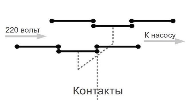
Place for pressure switch installation
It is recommended to install a pressure switch directly at the outlet to the accumulator, where pressure surges and flow turbulence are more leveled during pump start-up and operation. Also, for individual models, manufacturers limit the operating conditions for the microclimate, namely, the temperature is not lower than +4 degrees. and humidity not higher than 70%. Such relays must be installed in a heated room.Before the pump control sensor (pressure switch) in the water supply system, the following must be installed:
- Coarse water filter
- Pump and pipelines
- Inlet valve
- Fine water filter
- check valve
- Drain to sewer
Modern models of pumps are equipped with special fittings for connecting a pressure switch, as well as built-in filters and check valve. Therefore, individual pressure switches can also be mounted directly in the pump unit. If the relay is made according to a moisture-proof scheme, then it can be installed with a pump and in a caisson (pit) and even directly in the well. It all depends on the chosen model and the manufacturer's recommendations for temperature and humidity.
Definition of work parameters
Before selecting the pressure switch, the pumping unit and accumulator must already be selected, and the operating parameters of the network must be determined:- the maximum pressure in the system at which the pump will turn off;
- the minimum pressure at which the pump will turn on;
- pressure in the air chamber of the accumulator.
Please note that the minimum operating pressure in the water supply system must be 0.2 atm more than the pressure in the air chamber of the accumulator. Otherwise, increased wear of the elastic membrane is possible.
Please note that the relay can be:
- power, - including power contacts to the pumping unit;
- managing, - issuing a signal to the power control unit.
Check the allowable switching power of the relay. And how does this value relate to the selected pumping unit.
Design features and pressure setting
 The pressure switch of a simple design is a small device that is equipped with a fitting for connecting to a water pipe and a terminal group for connecting electrical cables. Registration of pressure parameters is carried out using springs, the force of which is adjusted by threaded regulators.
 The more the springs are compressed by the regulator, the more effort they create, and the higher the pressure is needed to trigger the relay (large spring), or the greater the pressure difference must be (small spring). Those. by tightening the springs we increase the values.
Typically, pressure switches designed for domestic use have factory spring settings that are fully suitable for domestic applications and common models of pumps and accumulators. For example, the minimum pressure is 1.5 atm. The maximum pressure is 3.0 atm.
However, due to some factors (considerations), sometimes it becomes necessary to adjust the pressure.
Pump pressure switch adjustment
- Typically, relays are equipped with two springs with different diameters.
- A spring with a large diameter controls the pressure levels.
- Spring with a small diameter - determines the difference in levels.
- By clamping a large spring, we increase the minimum and maximum pressure at the same time.
- By clamping a small spring, we increase the superiority of the maximum pressure over the minimum.
We advise you to read
, diagnosis, treatment Treatment of urogenital chlamydia") Chlamydia urogenital - description, causes, symptoms (signs), diagnosis, treatment Treatment of urogenital chlamydia
Chlamydia urogenital - description, causes, symptoms (signs), diagnosis, treatment Treatment of urogenital chlamydia The benefits and significance of hydroamino acid threonine for the human body L threonine what
 To wait or not to wait for a guy from the army For what reason can they be commissioned from the army
 Baked apples with cottage cheese Baked apples with cottage cheese

