Hi all! In this article I will describe in detail how to make a cool amplifier for home or car. The amplifier is easy to assemble and set up, and has good sound quality. Below you will find circuit diagram the amplifier itself.
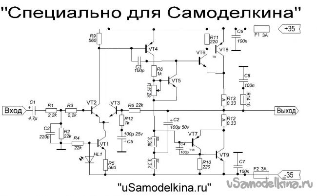
The circuit is made on transistors and has no scarce parts. The power supply of the amplifier is bipolar +/- 35 volts, with a load resistance of 4 ohms. When connecting an 8 ohm load, the power can be increased to +/- 42 volts.
Resistors R7, R8, R10, R11, R14 - 0.5 W; R12, R13 - 5W; the rest 0.25 W.
R15 trimmer 2-3 kOhm.
Transistors: Vt1, Vt2, Vt3, Vt5 - 2sc945 (usually c945 is written on the case).
Vt4, Vt7 - BD140 (Vt4 can be replaced by our Kt814).
Vt6 - BD139.
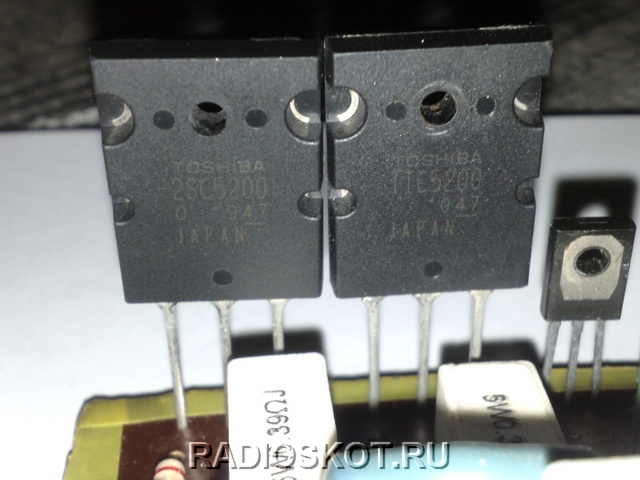
Vt8 - 2SA1943.
Vt9 - 2SC5200.
ATTENTION! The c945 transistors have different pinouts: ECB and EBK. Therefore, before soldering, you need to check with a multimeter.
The LED is ordinary, green, exactly GREEN! He's not here for beauty! And it should NOT be super bright. Well, the rest of the details can be seen in the diagram.
And so, let's go!
To make an amplifier, we need tools:
- soldering iron
-tin
- rosin (preferably liquid), but you can get by with the usual
- metal scissors
-cutters
-awl
- medical syringe, any
- drill 0.8-1 mm
- drill 1.5 mm
- drill (preferably some kind of mini drill)
-sandpaper
-and a multimeter.
Materials:
- one-sided textolite board measuring 10x6 cm
- sheet of notebook paper
-a pen
- varnish for wood (preferably dark color)
- small container
-baking soda
-lemon acid
-salt.
I will not list the list of radio components, they can be seen on the diagram.
Step 1 We are preparing a fee
And so, we need to make a board. Since I don’t have a laser printer (I don’t have any at all), we will make the board “the old fashioned way”!
First you need to drill holes on the board for future parts. Who has a printer, just print this picture:

if not, then we need to transfer the markings for drilling to paper. How to do this you will understand in the photo below:
when you translate, do not forget about the fee! (10 by 6 cm)

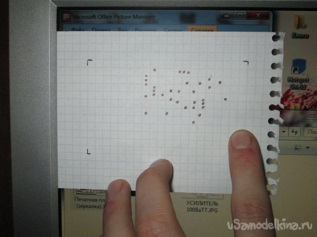
something like that!
We cut off the size of the board we need with metal scissors.

Now we apply the sheet to the cut out board and fix it with adhesive tape so that it does not move out. Next, we take an awl and outline (by points) where we will drill.

Of course, you can do without an awl and drill right away, but the drill can move out!

Now you can start drilling. We drill holes 0.8 - 1 mm. As I said above: it is better to use a mini drill, since the drill is very thin and breaks easily. For example, I use a screwdriver motor.


Holes for transistors Vt8, Vt9 and for wires are drilled with a 1.5 mm drill. Now we need to clean our board with sandpaper.

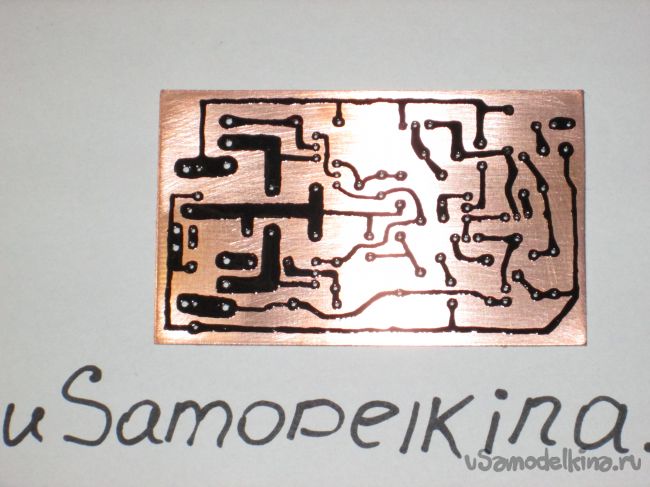
Now we can start drawing our paths. We take a syringe, grind off a needle so that it is not sharp, we collect varnish and go!

It is better to trim the jambs when the varnish has already hardened.
Step 2 We charge a fee
For board etching, I use the simplest and cheapest method:
100 ml of peroxide, 4 teaspoons of citric acid and 2 teaspoons of salt.

We stir and immerse our board.
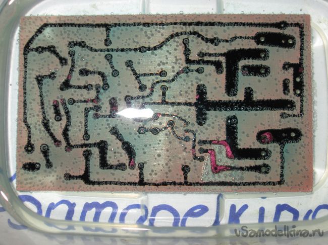

Next, we clean the varnish and it turns out like this!

It is advisable to immediately cover all the tracks with tin for the convenience of soldering parts.

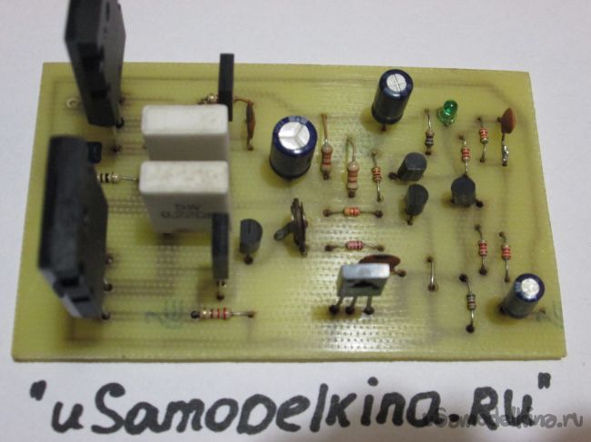
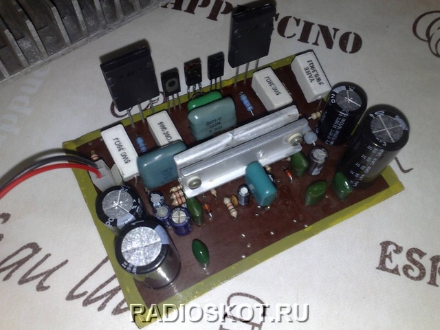
Step 3 Soldering and tuning
It will be convenient to solder according to this picture (view from the side of the parts)

For convenience, from the beginning we solder all the small parts, resistors, etc.
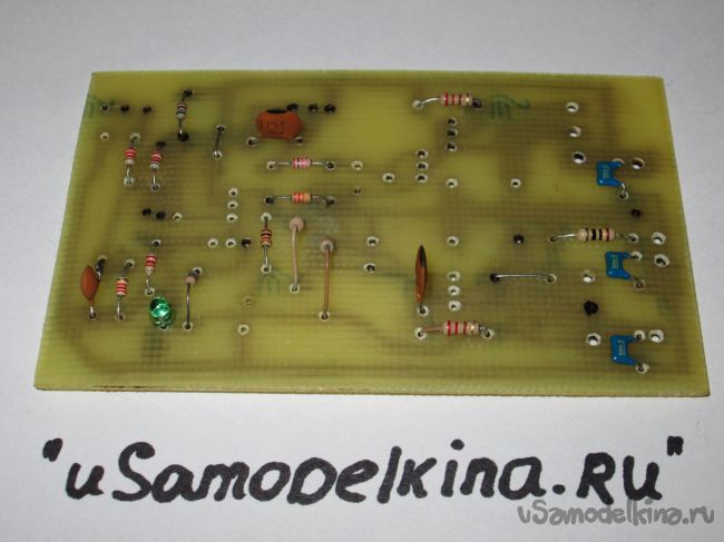
And then everything else.
After soldering, the board must be washed from rosin. You can wash it with alcohol or acetone. On kraynyak it is possible even gasoline.
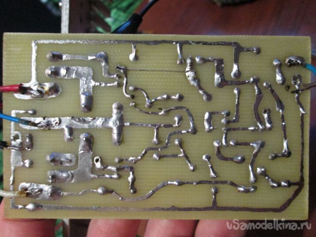
Now you can try to turn it on! With proper assembly, the amplifier works immediately. When you first turn on the resistor R15 must be turned in the direction of maximum resistance (we measure it with a device). Do not connect the column! The output transistors are MANDATORY on the radiator, through insulating gaskets.
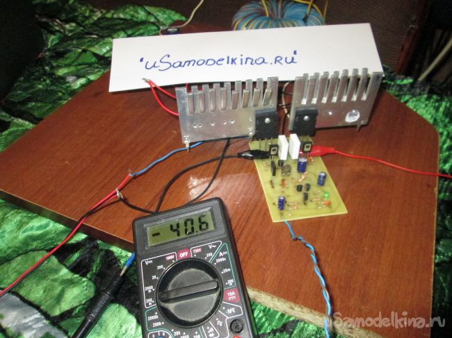
And so: turn on the amplifier, the LED should be on, we measure the output voltage with a multimeter. There is no standing, so everything is fine.
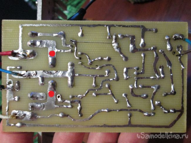
Next, you need to set the quiescent current (75-90mA): to do this, close the input to ground, do not connect the load! On the multimeter, set the mode to 200mV and connect the probes to the collectors of the output transistors. (marked with red dots in the photo)
Next, by slowly rotating the resistor R15, you need to set 40-45 mV.
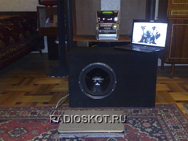
Exposed, now you can connect the speaker and drive the amplifier at a low volume for 10-15 minutes. Then again it will be necessary to correct the quiescent current.
Well, that's all, you can enjoy!
Here is a video of the amplifier in action:
Recently it was decided to build a 10W amplifier. There are many different specialized m / s on sale, but one friend recommended an amplifier based on the TDA2003 chip. This chip good quality and sound. It costs a penny these days. Even a beginner can assemble this amplifier, since in addition to the microcircuit itself, the circuit diagram has only 9 parts. These parts can be purchased at any radio store, or obtained from old equipment. Scheme of a 10-watt ULF on TDA2003:
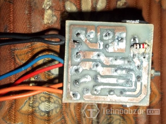
Perhaps many will have a problem with a 1 ohm resistor. It can be done by hand: taking a pencil and winding 10 turns of any wire thickness on it. By the way, the microcircuit can already work from 4.5v. I advise you not to apply more than 14v, because. thus, as a test, 2 microcircuits were burned. Rated power - 12v. In my case, three mobile phone batteries were used. Having soldered them in series, I got 11.4v (3.8x3) at the output. After finding the right power source, I began to assemble the amplifier circuit. First, I redrawn the printed circuit board for convenience. I made a drawing on the glass sheet and etched everything unnecessary.
I soldered it in 15 minutes - the details are at least. I connected it to a low-power power source for testing - everything worked from the first turn on. At 11.1v, the amplifier produced about 10 watts of power. This is exactly what I need.

It is advisable to install the microcircuit on a small radiator, as it can overheat and fail. With a lack of radiator area (overheating), the microcircuit starts to play badly and clumsily. There is printed circuit board in LAY format.

So, the hardest work remained - the manufacture of the case. This time I didn’t have to think for a long time: I took the box, pasted over it, installed the ULF circuit inside, made an output to the speakers and an input to the sound supply. I also added an LED that indicates power and its voltage. Everything else was placed in the body. Plays nice and loud. Happy repeating the design! Maxim Schaikow
12V battery in increased bipolar - you can proceed to the power amplifier itself. There are several channel amplifiers in the design.
TDA2005
- 20-25 watts are bridged. They are assembled on two separate boards for easy installation. Each of the amplifiers is activated when plus 12 volts is applied to the remote control output, this closes the relay and the amplifier is powered. Input capacitors can be selected to taste. Microcircuits are screwed onto a common heat sink through insulating gaskets.


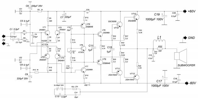

Zener diodes for 15 volts with a power of 1-1.5 watts, make sure they are installed correctly, when connected back they will work like a diode, there is a danger of burning the differential stage. Differential cascade - made on low-power complementary pairs, which can be replaced with others that are as similar as possible in terms of parameters. It is in this stage that the sound is formed, which is subsequently amplified and fed to the terminal (output stage). If you plan to make an amplifier for 100-150 watts, then you can exclude the second pair of the output stage, since the power of the amplifier directly depends on the supply voltage. With one pair of outputs, it is not advised to increase the supply voltage above +/-45 volts. If you are planning to assemble a subwoofer amplifier, then this circuit is what you need! variable resistor adjust the quiescent current of the amplifier, the further service life of the circuit depends on it.
Before soldering trimmer resistor R15, it must be “unscrewed” so that its impedance is soldered into the gap of the track. You need to take a multi-turn resistor, they can very accurately adjust the quiescent current, it is also very convenient for further tuning. But of course, if it is not already there, then you can get by with an ordinary trimmer, but it is advisable to remove it from the common board with wires, since after installing all the components, tuning will be almost impossible.
The quiescent current is adjusted after "heating the circuit", in other words, turn it on for 15-20 minutes, let it play, but don't get carried away! The quiescent current is an important factor, without proper tuning the amplifier will not last long, the correct operation of the output stage and the level of constant at the output of the amplifier depend on it. The quiescent current can be found by measuring the voltage drop across a pair of emitter resistors (set the multimeter to the limit of 200mV, the probes to the VT10 and VT11 emitters). Calculation according to the formula: Ipok \u003d Uv / (R26 + R26). Next, smoothly rotate the trimmer and look at the readings of the multimeter. You need to set 70-100mA - this is equivalent to a multimeter reading (30-44) mV. Checking the level constant voltage at the exit. And now everything is ready - you can enjoy the sound of an amplifier assembled by yourself!
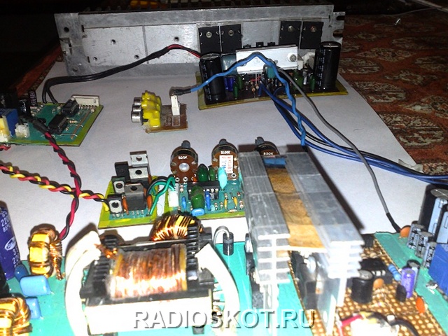
A small addition. Having assembled the UMZCH, you need to think about heat sinks. The main heat sink was taken from a domestic amplifier RADIO U-101 STEREO- it almost does not heat up during operation. Low-power diff-cascade transistors heat up, but overheating is not terrible, so they do not need cooling. The output transistors are screwed to the main heat sink through insulating gaskets, it is also desirable to use thermal paste, which I did not.
All other transistors can be installed on small separate heat sinks, or you can use a common one (for each stage), but in this case you need to screw the transistors through spacers. IMPORTANT ! All transistors must be screwed to the radiators through insulating gaskets, there should not be any short circuits on the bus, therefore, before turning on, carefully check with a multimeter whether the transistor leads are closed to the heat sink. We can consider the assembly of the device completed, but for today I say goodbye to you - AKA KASYAN.
Discuss the article AMPLIFIER WITH YOUR HANDS - BLOCK UMZCH
We advise you to read
 Psychological characteristics of children in adolescence
 Transferring a child to another school - the procedure and necessary documents Whether to transfer a child to another school
, diagnosis, treatment Treatment of urogenital chlamydia") Chlamydia urogenital - description, causes, symptoms (signs), diagnosis, treatment Treatment of urogenital chlamydia
Chlamydia urogenital - description, causes, symptoms (signs), diagnosis, treatment Treatment of urogenital chlamydia The benefits and significance of hydroamino acid threonine for the human body L threonine what

