For correct connection sockets you will need the following tools: a flat or Phillips screwdriver to tighten the contacts; construction knife or side cutters for stripping wires from insulation; indicator screwdriver and a tester for determining the phase and zero.
How to connect a single socket without grounding
If you need to properly connect a single outlet, and two wires come out of the wall, then everything is simple here. Make sure that one outgoing wiring is phase, and the second is zero with the help of an indicator - a screwdriver when the introductory machine is turned on, which is usually located on the landing, if it is an apartment. In a private house near electric meter there may be two plugs, that is, fuses that must be screwed in.
After checking with an indicator screwdriver, if there is a phase and zero, we de-energize the room from voltage by unscrewing the plugs or turning off the introductory machine to the house. We play it safe and check the indicator for the absence of voltage on both wires. Now you can connect the socket contacts to them.
We clean from isolation each wire with a knife for a length of 7-8 mm., This is enough for the stripped core to stick through the entire contact. You don’t need to strip it anymore, since the extra part of the wiring that is exposed from the insulation can touch the conductive parts of the outlet or the adjacent contact. short circuit.
On the inside of the socket, alternately loosen the two clamping contacts with a screwdriver. After each, we push one of the two cores and tighten the two screws. It doesn't matter where you plug it in.
There are not only screw ones, there are self-clamping contacts in them, you need to force the core into the hole, or if there is a lever, push it.
Wires are sometimes different colors (color marking): blue, - zero, brown - phase, green - ground
4 cores can leave the wall, when a single socket is connected, this means that it will also act as a jumper to another, which in most cases is located on the opposite side of the wall at the same level.
Here it is important to define exactly indicator screwdriver and a tester, which of the four conductors is the incoming phase and zero, and then the other two - these will be the outgoing conductors from this socket to another.
So, turn on the introductory machine, touch the tip indicator screwdriver to each of the four cores. There must be a phase on one conductor - remember it. Zero will be more difficult to calculate. We find the nearest working outlet, we recognize zero with the indicator. Taking the tester, put its regulator in the continuity position (determining the minimum resistance). With one probe we set to zero in the working outlet, and with the second we touch each of the three remaining uncalculated conductors. One of the three wires should ring, that is, show the circuit - it will be zero, we remember it too. Any of the other two cores should not ring relative to the zero of another outlet or show a phase on itself, since these cores will just take power to another opposite socket.
When we found out which vein is responsible for what we de-energize the house from voltage. We check the absence of voltage. We clean four conductors from insulation.
Now that we know the phase, we connect it to any of the two wires that go to another outlet. And the zero, which we previously remembered, is connected to the remaining second conductor, which goes to the adjacent outlet.

Next, we insert into each contact of a single socket one twist of two cores obtained and clamp it. After fix the inside of the socket and install the plastic case.
How to connect a double socket without grounding
double rosette connects in the same way as a single one, only it has two additional connecting plates.
If two conductors come from the wall, and you want to plug in a double socket, after checking the presence of a phase on one of the conductors, we turn off the voltage in the house. We clean the two wires with a knife. Next, we connect one wire to one bolted contact of one plate, and the other to the other opposite plate and clamp it tightly.

In the case when you need to connect a double socket, and four wires or six come from the wall, then you need to calculate one phase conductor from them and one zero, and the remaining four wires - they also feed the next two from this outlet. How to determine where which one is written at the beginning of the article.
Grounded sockets, have a ground connection in the middle with a metal bracket. There must also be such a grounding bracket on the plug of the device. Thus, from the ground loop through the socket-plug connection, the loop itself is connected to the device case. That is, the device is grounded and when voltage hits its case, most of the voltage will go to the ground. If you have house wiring with grounding, in this case, another core will come out of the walls Green colour. It must be connected to the ground connection of the socket that has it.
It must be remembered that work under a voltage of 220 volts, alternating current dangerous to life. Often people do it themselves wiring in the apartment. Therefore, check the absence of voltage several times before touching live parts.
It is quite simple in its execution and will certainly come in handy in the arsenal of building experience for every man. Making repairs once again, I probably wanted to add an additional outlet somewhere, but having no general idea of how to do it, I don’t really want to take on this business. The detailed information in this article will help you socket wiring diagram.
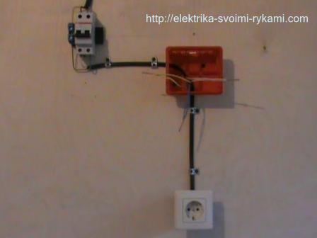
Let's bring good example, in it we will consider the full version of the installation and connection of the cores of the wires into the socket circuit with grounding. Our example is made in a compact version, it is a hidden electrical wiring and usually everything you see is under the plaster and at a distance from each other. The scheme of external wiring and in the internal are the same.
Installation of pre-installation circuit elements
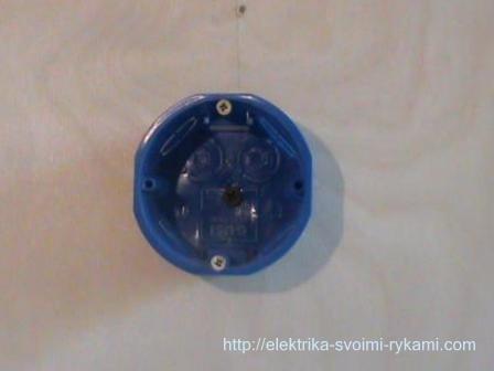
First of all, it is necessary to install a junction box, in which the wires will be connected into a finished circuit.

Next, we will simulate a power shield with protection devices installed in it. Since we have one direction, we will install one machine. We mount the Din - rail, on which we will fix the modular circuit breaker, which will protect the circuit from a short circuit.
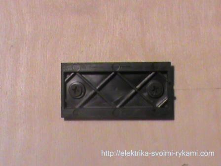
Now, install a socket, a socket mechanism will subsequently be installed in it.
If necessary, you can refer to step by step instructions for installation, they are presented on our resource in articles of the same name, and.
We lay the wires necessary to complete the circuit
First of all, we mount the power wire, through which voltage will be applied to the circuit protection device.
Attention! If the wire is already present and there is voltage on it, be sure to disconnect it before carrying out all work. Then, without fail, make sure that it is not on the wire. To check the fact of its absence, use the voltage indicator. You can read the instructions for working with this device in the article.


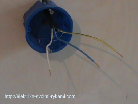
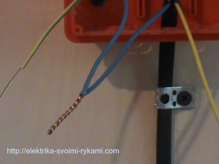
Now, we draw and fasten the last wire of our circuit, from junction box to the socket.
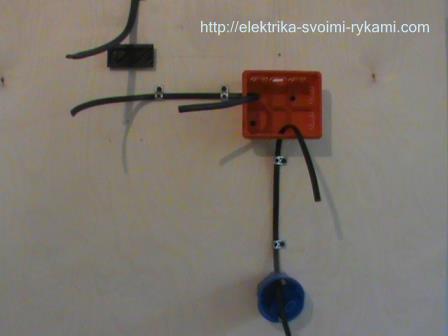
The ends of the wires in the junction box should be 10-15 centimeters long.
 On the socket to connect the outlet, 10 centimeters is enough.

All necessary wires the circuits are mounted, we proceed to the installation of the installation equipment.
Installation of the installation equipment of the socket circuit
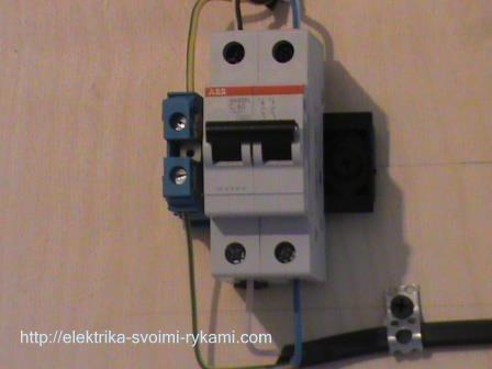
Let's start by installing and connecting the protection device. In our example, this function is performed by a two-pole circuit breaker, it protects the circuit from overloads and short circuit currents. You can learn more about what circuit breakers are, what functions they perform and what their principle of operation is in the article. . You can study the detailed instructions for connecting a two-pole machine in the article .
We prepare suitable and outgoing wires. The wire we use is three-core, has double insulation, which consists of a common outer sheath and an inner one, individual for each of the cores, with a color designation of the insulating layer.
We remove the outer insulation. Before us are three multi-colored veins at the top and three at the bottom. At different cable factories, the color of the cores may vary somewhat, but the main colors and shades remain unchanged. Each three-wire wire has a blue tint and yellow or yellow-green.
Before you install the circuit, you need to decide on the color of the cores. Let's see which colors are most widely used in electrical designations:
- blue - zero;
- yellow or
- The vein of the remaining color will be a phase, in most cases its color is white or black, less often red, orange or brown.
For our specific example, on the (upper) wire suitable for the machine:
- white wire with a blue stripe - will be zero;
- white wire with a black stripe - phase;
- yellow with a green stripe - earth.
On the outgoing (lower) wire:
- blue - zero;
- white - phase;
- yellow with a green stripe - earth.
It is advisable to use the wire of one cable factory, so you are guaranteed not to get confused in the colors.
We measure the length of wire cores required for connection. Then, remove 1 centimeter of the insulating layer from each of the cores.
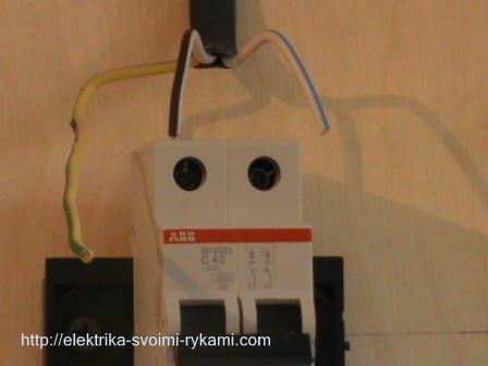

We connect the blue and white wires to the contacts of the machine.
For the grounding conductor, we use a through contact.

The lower cores of the wire that goes to the junction box are connected in the same way. I note that the connection of the wires should be symmetrical, if the top of the machine is zero on the right, then it should be on the right from the bottom, the phase is on the top left and bottom left.

The connection of the security device is completed.
 We proceed to connect the socket with grounding. We remove the outer insulation of the wire.

We connect the cores of the wires to the contacts of the socket mechanism. The white and blue wires are connected to the power contacts of the socket, and we put the yellow wire with a green stripe into the ground contact.

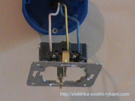
The connection of the socket with grounding is completed. Now, install the socket mechanism in the socket.
You can find a more detailed separate instruction located on our website by clicking on the link.

Let's move on to the next step.
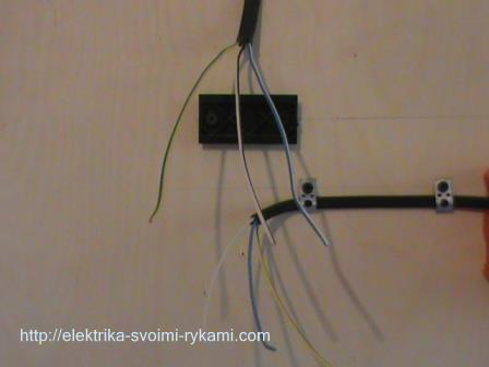
We connect the cores of the wires in the socket connection diagram
Two wires are involved in our scheme, feeding the junction box (located on the left) and going to the outlet (located at the bottom), we remove the outer insulation from both wires.
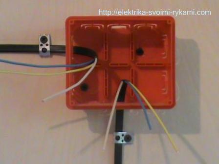
The connection of the cores in the circuit will be made by twisting the wires together.
On the this stage I want to draw your attention to one important point. In the example, the twisting method is used, since it is the most visual for understanding and perceiving the principle of executing the circuit. At present, the rules for the installation of electrical installations in pure form this method is prohibited by the PUE p2.1.21.
The permitted methods of connecting wire cores include:
- crimping;
- welding;
- soldering;
- screw, clamp and similar clamps.
This issue will be discussed in more detail in the corresponding instructions, the article is currently being written, but will appear on our resource in the near future.

We twist together first two white, phase conductors of the wire.

We stretch the finished twist with pliers, bite off the protruding ends.

Similarly, we connect two blue, zero wire cores.
Then, two ground wires.

The socket wiring diagram is complete.


We install a protective cover on the socket mechanism.
We isolate the twists of wires with an insulating tape.

And put them in a junction box.

Now, we need to check the performance of the finished circuit. To do this, we apply voltage to it by moving the lever of the circuit breaker from the lower position - "off", to the upper position - "on".
We perform the check first with a voltage indicator, then, using any electrical appliance, simply by plugging it into a power outlet.
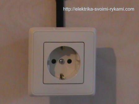
The socket is ready for use.
Picture. Socket connection diagram.

In this work, we used the following material:
- junction box - 1 pc.;
- socket box - 1 pc.;
- wire - measured according to the specific measurements of your room;
- socket - 1 pc.;
- ground contact - 1 pc.;
- bipolar automatic switch - 1 piece;
- insulating tape - 1 pc.
How much we saved by making a do-it-yourself socket connection diagram:
- call an electrician - 200 rubles;
- junction box installation indoor installation- 550 rubles;
- installation of an indoor socket outlet (making a hole, installation) - 200 rubles;
- installation of a two-pole machine - 300 rubles;
- installation of a ground contact - 120 rubles;
- chasing walls (1 meter - 120 rubles, for example, take 8 meters) - 960 rubles;
- installation of the wire openly, up to 2 meters high (for example, 2 meters, down to the outlet, 1 meter - 35 rubles) - 70 rubles;
- installation of wire over 2 meters (1 meter - 50 rubles, for example 8 meters) - 400 rubles;
- installation and connection of a socket with grounding of a hidden installation - 200 rubles.
TOTAL: 3000 rubles
* Calculation is made for electrical wiring of hidden execution

. Connecting and installing a double socket is no different from connecting and installing a single one. Depending on the three- or two-wire electrical network (with or without grounding), the socket is connected with a three- or two-wire wire.
1. Connecting an outlet to a two-wire network.
Consider the option when you have a two-wire electrical network (without grounding) and a single socket is installed, which you want to replace with a double one.
Every socket is made up of decorative cover and working part which are screwed together. Before installing the outlet, both these parts are separated from each other. If this is not done, then the installation and connection of the working part will not work.

The decorative cover is made of plastic and, depending on the design of the socket, is attached to the working part with one or two screws. The screws are unscrewed with a screwdriver and both parts are freely separated from each other.


Now you need to dismantle the old outlet, but before dismantling it must be de-energized. If it is not possible to turn off the voltage from this outlet, then we de-energize the entire room, apartment or house. And only after checking the absence of voltage on the contacts of the socket, we proceed to dismantle it..
First of all, unscrew the screws securing the decorative cover.
After removing the cover, the working part of the socket remains in the wall, and in order to pull it out, it is necessary to loosen the fastening with which the socket is rigidly held in the socket. To do this, unscrew two side screws located on the left and right side of the working part.

The side screws are part of the fastening and serve to fix the socket in the socket. When twisted, they press on spreader legs, which move apart to the sides and abut against the side walls of the socket, rigidly holding the socket. And to relieve the pressure on the spacer legs, these screws are unscrewed.


The side screws are unscrewed alternately. First, one screw is unscrewed a few turns, then the second. In this case, the working part adheres to the fingers. When the mount is loosened, the working part can be freely pulled out of the socket.


Now it remains only to disconnect the wires from the terminal clamps of the old outlet and proceed to connect the new one.
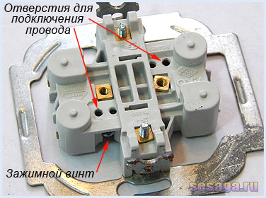
Depending on the design of the socket, the terminal clamps can be located on the side, in front or behind the base of the working part. In my case, the holes for entering the wire strands are located at the back of the base, and the screw that clamps them is located on the side.


Advice. Before installing the socket, cut the ends of the wire again. Bite off the ends that went into the terminal connections, and then peel them again from the insulation by about 1 cm. In this way, we get ends free of all oxides and, of course, a clean and reliable contact connection. If the wire is stranded, then twist the veins with pliers into a tight twist.

Now all work on connecting a new outlet is carried out in the reverse order: power wires are connected, the working part is fixed in the socket, and at the end a decorative cover is installed. However, there are a few nuances that you may not be aware of.
1 . The location of the phase and neutral wires in the socket.
It does not matter which terminal (right or left) to apply phase or zero. It is desirable that the location of the phase and neutral conductors in all sockets of the house coincide. The same location is convenient for maintaining the home electrical network and troubleshooting.
When the working part is recessed in the socket, then at first it is aligned horizontally. Then it is pressed tightly against the wall and the side screws are tightened until the spacer legs firmly rest against the side walls of the socket and fix the working part.
The side screws are tightened alternately: first, for example, the left screw is screwed in a few turns, and then the right screw. In the process of tightening the side screws, the working part is held from the sides so that it is not squeezed out of the socket.

3 . Wire length.
If the socket is installed at a new point, then before connecting, check the length of the wire, which should be no more than 15 - 20 cm. If the wire is left longer, then there is a possibility that the socket will not fit in the socket.
4 . The location of the wire in the socket.
When installing the socket in the socket, the wire is laid first (it is folded into a ring or arranged with an accordion), and then the working part is inserted, which presses the wire to the bottom of the socket. Be careful not to get the wire in the area of the spreader tabs.. If this is allowed, then the legs will either crush the wire or break the insulation. In both cases we get short circuit and a broken outlet or line.
Connecting an outlet to a three-wire electrical network has a slight difference. The difference lies in the presence of an additional third wire, called or grounding which is connected to ground contact sockets.
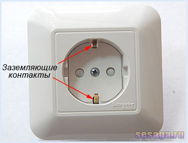
Accordingly, a socket with grounding has a slight structural difference from a socket without grounding. A grounded outlet has grounding contacts made in the form of a spring-loaded brass plate and protruding at the point where the plug is connected. Everything else is unchanged.


The terminals for connecting the power wire in the socket shown in the figure are located in the lower area of the working part. The location of the phase and neutral wires is shown as an example. In your case, the phase wire can be located on the right side, and the neutral wire on the left.
![]()
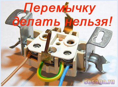
And more advice. Never put a jumper in the socket between the ground and zero contact.. The jumper will not protect you, but will only create problems. If in the house two-wire network, then connect only the phase and zero.
Now I hope you should not have any questions with double socket connection.
Thank you for your attention. Goodbye.
Good luck!
We advise you to read
, diagnosis, treatment Treatment of urogenital chlamydia") Chlamydia urogenital - description, causes, symptoms (signs), diagnosis, treatment Treatment of urogenital chlamydia
Chlamydia urogenital - description, causes, symptoms (signs), diagnosis, treatment Treatment of urogenital chlamydia The benefits and significance of hydroamino acid threonine for the human body L threonine what
 To wait or not to wait for a guy from the army For what reason can they be commissioned from the army
 Baked apples with cottage cheese Baked apples with cottage cheese

