When a charge is communicated to a conductor, a potential φ appears on its surface, but if the same charge is communicated to another conductor, then the potential will be different. It depends on the geometric parameters of the conductor. But in any case, the potential φ is proportional to the charge q.
The SI unit for capacitance is the farad. 1 F \u003d 1C / 1V.
If the potential of the surface of the ball
 |
(5.4.3) |
|
|
(5.4.4) |
More often in practice, smaller units of capacitance are used: 1 nF (nanofarad) \u003d 10 -9 F and 1pkF (picofarad) \u003d 10 -12 F.
There is a need for devices that accumulate charge, and solitary conductors have a low capacitance. Experienced it was found that the electric capacitance of a conductor increases if another conductor is brought to it - due to phenomena of electrostatic induction.
Capacitor are two conductors called facings located close to each other .
The design is such that the external bodies surrounding the capacitor do not affect its electrical capacity. This will be done if the electrostatic field is concentrated inside the capacitor, between the plates.
Capacitors are flat, cylindrical and spherical.
Since the electrostatic field is inside the capacitor, the electric displacement lines start on the positive plate, end on the negative one, and do not disappear anywhere. Therefore, the charges on the plates opposite in sign but equal in magnitude.
The capacitance of a capacitor is equal to the ratio of the charge to the potential difference between the capacitor plates:
|
|
(5.4.5) |
In addition to capacitance, each capacitor is characterized by U slave (or U etc . ) - the maximum allowable voltage, above which a breakdown occurs between the capacitor plates.
Connection of capacitors
Capacitive batteries– combinations of parallel and series connections of capacitors.
1) Parallel connection of capacitors (Fig. 5.9):
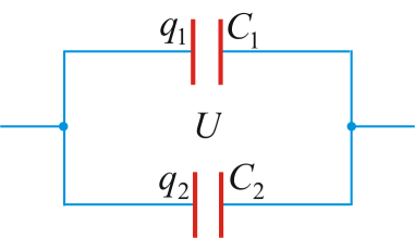
In this case, the common voltage is U:
Total charge:
Resulting capacity:
![]()
Compare with parallel connection of resistances R:
Thus, at parallel connection capacitors total capacitance
The total capacity is greater than large capacity included in the battery.
2) Series connection of capacitors (Fig. 5.10):
Common is the charge q.
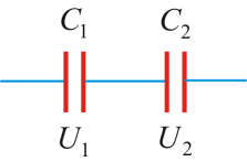
Or ![]() , hence
, hence
| (5.4.6) |
Compare with serial connection R:
Thus, at serial connection capacitors, the total capacitance is less than the smallest capacitance included in the battery:
Calculation of capacities of various capacitors
1.Capacity flat capacitor
Field strength inside the capacitor (Fig. 5.11):
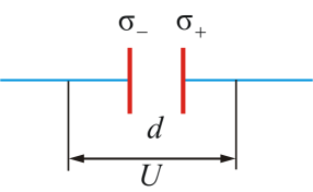
Tension between plates:

where is the distance between the plates.
Since the charge
|
|
(5.4.7) |
As can be seen from the formula, the dielectric constant substances greatly affect the capacitance of the capacitor. This can also be seen experimentally: we charge the electroscope, bring a metal plate to it - we got a capacitor (due to electrostatic induction, the potential increased). If a dielectric is introduced between the plates with ε greater than that of air, then the capacitance of the capacitor will increase.
From (5.4.6) you can get the units of measurement ε 0:
| (5.4.8) |
![]() .
.
2. Capacitance of a cylindrical capacitor
The potential difference between the plates of the cylindrical capacitor shown in Figure 5.12 can be calculated by the formula:
![]()
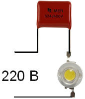
Transformerless power supplies with a quenching capacitor are convenient in their simplicity, have small dimensions and weight, but are not always applicable due to the galvanic coupling of the output circuit with a 220 V network.
In a transformerless power supply to the network AC voltage capacitor and load connected in series. Non-polar capacitor included in the chain alternating current, behaves like a resistance but, unlike a resistor, does not dissipate the absorbed power as heat.
To calculate the capacitance of the quenching capacitor, the following formula is used:
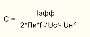
C - capacity ballast condenser(F); Ieff - effective load current; f is the frequency of the input voltage Uc (Hz); Us - input voltage (V); Un - load voltage (V).
For ease of calculation, you can use the online calculator
Design transformerless sources and devices powered by them, should exclude the possibility of touching any conductors during operation. Particular attention should be paid to the isolation of controls.
- Similar articles
Operating frequency range 66 ... 74 or 88 ... 108 MHz Using R7, the separation between the AF channels is regulated. *** The signal is fed from the output of the VHF (FM) frequency detector - the receiver to the input DA1 through the corrective circuit R1C1. Literature J.Radioamateur 1 2000.
The need to connect the LED to the network is a common situation. This is an indicator for turning on devices, and a backlit switch, and even a diode lamp.
There are many schemes for connecting low-power indicator LEDs through a resistor current limiter, but such a connection scheme has certain disadvantages. If you need to connect a diode with a rated current of 100-150mA, you will need a very powerful resistor, the dimensions of which will be much larger than the diode itself.
This is how the desktop connection diagram would look like light diode lamp. And powerful ten-watt resistors at low room temperatures could be used as an additional source of heating.
The use of a conder-ditch as a current limiter can significantly reduce the dimensions of such a circuit. It looks like a power supply for a diode lamp with a power of 10-15 watts.
The principle of operation of circuits on a ballast capacitor
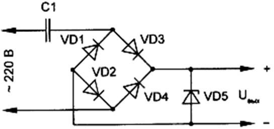
In this circuit, the capacitor is a current filter. Voltage is supplied to the load only until the capacitor is fully charged, the time of which depends on its capacity. In this case, no heat generation occurs, which removes restrictions on the load power.
To understand how this circuit works and the principle of selecting a ballast element for LED, let me remind you that voltage is the speed of electrons along the conductor, current strength is the density of electrons.
For a diode, it is absolutely indifferent at what speed electrons will “fly” through it. The calculation of the capacitor is based on the current limitation in the circuit. We can apply at least ten kilovolts, but if the current strength is several microamperes, the number of electrons passing through the light emitting crystal is enough to excite only a tiny part of the light emitter and we will not see the glow.
At the same time, at a voltage of several volts and a current strength of tens of amperes, the electron flux density will significantly exceed the throughput of the diode matrix, converting the excess into thermal energy, and our LED element will simply evaporate in a puff of smoke.
Calculation of the quenching capacitor for the LED
Let's analyze the detailed calculation, below you can find the form of an online calculator.
Calculation of the capacitor capacitance for the LED:
C (μF) \u003d 3200 * Isd) / √ (Uin² - Uout²)
With uF- the capacity of the condenser. It should be rated for 400-500V;
Isd – rated current diode (look in the passport data);
Uin- amplitude voltage of the network - 320V;
Uout– nominal supply voltage of the LED.
You can also find this formula:
C \u003d (4.45 * I) / (U - Ud)
It is used for low power loads up to 100 mA and up to 5V.
Calculation of the capacitor for the LED (online calculator):
For clarity, we will calculate several connection schemes.
To calculate the capacity of the conduit, we need:
- The maximum diode current is 0.15A;
- diode supply voltage - 3.5V;
- peak voltage of the network - 320V.
For such conditions, the parameters of the conduit are: 1.5 μF, 400V.
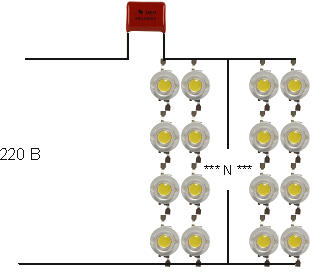 When calculating a capacitor for an LED lamp, it must be taken into account that the diodes in it are connected in groups.
- Supply voltage for a serial chain - Usd * number of LEDs in the circuit;
- current strength - Iсd * number of parallel chains.
For example, let's take a model with six parallel lines of four series diodes.
Supply voltage - 4 * 3.5V = 14V;
Circuit current - 0.15A * 6 \u003d 0.9A;
For this circuit, the parameters of the capacitor are: 9 microfarads, 400V.
A simple LED power supply circuit with a capacitor
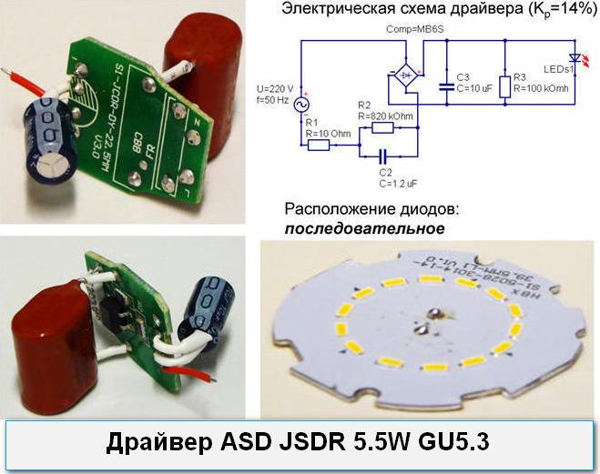
Let's analyze a device without a transformer power supply for LEDs using the example of a factory LED llama driver.
- R1- 1A resistor, which reduces the significance of voltage drops in the network;
- R2,C2- Conde-r serves as a current limiter, and a resistor for discharging it after disconnecting from the network;
- C3- smoothing condenser, to reduce the pulsation of light;
- R3- serves to limit voltage drops after conversion, but it is more advisable to install a zener diode instead.
What capacitor can be used for ballast?
Ceramic elements rated for 400-500V are used as quenching capacitors for LEDs. The use of electrolytic (polar) capacitors is unacceptable.
Precautionary measures
Transformerless circuits do not have galvanic isolation. The current strength of the circuit when additional resistance appears, for example, touching a bare contact in the circuit with a hand, can increase significantly, causing electrical injury.
We advise you to read
, diagnosis, treatment Treatment of urogenital chlamydia") Chlamydia urogenital - description, causes, symptoms (signs), diagnosis, treatment Treatment of urogenital chlamydia
Chlamydia urogenital - description, causes, symptoms (signs), diagnosis, treatment Treatment of urogenital chlamydia The benefits and significance of hydroamino acid threonine for the human body L threonine what
 To wait or not to wait for a guy from the army For what reason can they be commissioned from the army
 Baked apples with cottage cheese Baked apples with cottage cheese

