Radio 2003 - 11 pp. 38, 39
Operator's device
R. YARESHKO, Kharkiv, Ukraine
In the literature, you can find descriptions of various devices for checking and repairing telephone sets, both with their connection to PBX lines, and autonomously. However, many of them are quite complex.
Using this device, you can, without connecting to the PBX lines, check the operation of electromechanical bells and electronic ringing devices of telephone sets (SLT), their speaking units and dialers. The device can autonomously test not only fully equipped disk and push-button SLTs (including cordless ones), but also separately disk dialers, as well as PDT-1, PDT-2, PDT-Z.DP-1 diode circuit separation attachments used on paired lines .
The scheme of the device is shown in fig. 1. It consists of three main components: a telephone line simulator, a dial tone generator, and a dial pulse recorder. The operating mode is selected by switch SA2. In the upper (according to the diagram) position of its movable contact, the "Answering station" mode is enabled, and in the lower position - "Checking the dialer". There is an auxiliary mode "Call test", activated by pressing the SB2 button in any of the main modes.
The line simulator consists of diodes VD1-VD4, capacitor C1, resistors R1-R3, relay windings K1 and K2. Until the connected SLT is off-hook, constant pressure at its terminals is 60 V. With the tube raised, it drops to 5 ... 15 V, depending on the type of TA.
The signal generator "Station response" with a frequency of approximately 400 Hz is assembled on transistors VT1 and VT2. The frequency can be changed by selecting the value of the resistor R4. This signal is fed to the output of the device through an isolating transformer T2. Since the power supply to the generator is supplied through the SA2 operation mode switch and the K1.1 relay contacts, the operation of this relay when the handset is picked up causes a continuous beep in the phone.
For the purpose of simplification, as a ringing signal, AC voltage frequency 50 Hz with secondary winding transformer T1, connected to the TA by the contacts of the button SB2.
The dial pulse recorder is assembled on a decimal counter with a DD1 decoder and a seven-element LED indicator HG1. The dialing pulses from the movable contact of relay K2.1 are fed to the counting input DD1. By pressing the SB1 button, the counter is returned to its original zero state.
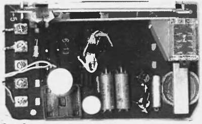
One of the variants of the device is mounted on a board from a TA-68 telephone set (Fig. 2), from which all elements are removed, with the exception of the lever switch, which acts as an SB2 button, and the conversation node transformer (it is used as T2). The SB1 button is absent in this version; to set the counter DD1 to its initial state, press the lever switch of the tested TA the required number of times.
The alternating voltage on the winding II of the transformer T1 is 50 ... 60 V, on the winding III - 8 ... 10 V. Transformer T2 - from the conversational node of the TA-68 device, winding I - with a smaller number of turns, II - with a large . Any diodes VD1-VD8 for a current of at least 50 mA with a permissible reverse voltage of at least 100 V. Relays K1 and K2 - RES55A, passport RS4.569.600-02, RS4.569.600-07 or RS4.569.600-11. Transistors VT1 and VT2 - any low-power corresponding structure.
Setting up the device start by setting a voltage of 60 V at its output by selecting the value of the resistor R3. If you close the clamps for connecting the TA to each other, the PA1 milliammeter should show a current of 30 ... 40 mA. This is achieved by selecting the values of the resistors R1 and R2.
Having connected the tested TA to the device, turn on the power supply of the latter with the SA1 switch. Without lifting the handset, you can check the operation of the ringing device (call) by pressing the SB2 button. Next, set the SA2 switch to the "Answer station" position. When lifting the TA tube, a continuous beep should be heard in it, and the PA1 microammeter should show the current flowing through the device. Then, SA2 is moved to the "Check dialer" position. Before dialing each digit, using the SB1 button, zero is set on the HG1 indicator. At the end of dialing, the number on the indicator should correspond to the dialed one. When checking electronic SLTs, it is useful to swap their terminals, as some faults manifest themselves differently depending on the polarity of the connection.
Disk three- and five-wire dialers are checked by connecting their red and yellow wires to the terminals of the device, which is in the “Dialer Test” mode. The serviceability of the prefixes of the diode circuit separation is verified by connecting them with the correct polarity between the device (the top wire in the diagram is positive) and a known good TA. In this case, the "Answer station" mode must be enabled. It is not possible to check the ringer of an SLT connected in this way.
The device was tested when checking telephone sets TA-70, Spektr-201 M, PANASONIC KX-TCM943, attachments for diode separation of circuits DP-1, rotary dialers of various types.
This theme was continued in the magazine #10 of 2004. The continuation is available at the link "Improvement of the "Telephone Operator's Device""
Taking into account the wishes of the workers, including communications fitters, a continuous mode has been added to the generator for checking telephone lines, described in my article.
Scheme
In general, the generator has not changed much, with the exception of the output circuit. The master oscillator is assembled on a DD1 chip, the frequency of which (in the range of 500 - 1000 Hz) can be selected by changing the resistance of the resistor R1.The generator has two modes of operation: standby and continuous. To turn on the generator, the SA2 switch is moved to the "GEN" position.
In standby mode, the middle contact of the dual switch SA1 is in the lower position on the diagram, the generator supply voltage is supplied to the measuring circuit, while the generator is in standby mode until the circuit from the other end of the line is closed to direct current.
In continuous mode, the middle contact of the dual switch SA1 is in the upper position on the circuit, the supply voltage is supplied through the contacts SA1.2 to the microcircuit DD1 and transistors VT1 and VT2, and a continuous signal from the output transistors VT1 and VT2 through the capacitor C2, contacts SA1.2 and the telephone capsule BF1 is fed into the measuring line.
In continuous mode, the BF1 telephone capsule may sound weak due to the capacitance between the wires of the cable. But this effect can be used to roughly determine the location of a line break, an experienced fitter can determine the location of the break by ear with an accuracy of ± 20 meters. For example, electrician S.G. Ermakov used such a generator to determine by ear in which cabinet, shield or section of the line there was a break.
If the SA2 switch is switched to the "TLF" position, then the internal telephone capsule BF1 can be used to check the existing subscriber line for the presence of a "buzzer".
Construction and details
According to this scheme, several simple, small-sized generators were made to test telephone lines.
Transistors VT1 - VT3 are silicon, for example VT1, VT3 - KT503V, KT3102B, KT815B, KT817B, VT2 - KT502V, KT3107B, KT814B, KT816B, with the latter being more desirable (to increase reliability).
Diodes VD1, VD2 - silicon designed for a direct current of at least 50 mA, zener diodes VD3, VD4 for a stabilization voltage of 12 - 15 V, for example KS213A, D814D, KS515A. BF1 - a telephone capsule or speaker with a DC resistance of 50 - 100 ohms.
Battery GB1 for voltage 4 - 12 V.
Correctly assembled, without errors, device does not need adjustment. We connect the generator in the measured line from one end, and from the other - a telephone capsule with a resistance of 50 - 500 Ohms, with a good line, we hear sound both in the generator and in the capsule at the other end.
Thank you for your attention!
Vasily Melnichuk (UR5YW), Evgeny Bocharnikov.
When you restore work cable lines communication, it is convenient to use a low-frequency generator (LF) and a telephone capsule for “dialing” of individual cable cores. But using a conventional generator that produces a continuous signal to the line, with a cable route length of more than 2 km, almost the entire cable “rings” due to capacitance and leakage between the cores, it becomes difficult to determine the right pair.
It was decided to supply the generator power to the measuring circuit as well, while the generator is in standby mode until the circuit from the other end of the line is closed by direct current.
Using the proposed idea, a dozen simple, small-sized generators were made to test telephone lines (Fig. 1) for signalmen.
The device consists of a generator on a DD1 chip, the frequency of which (in the range of 800 - 1000 Hz) can be selected by changing the resistance of the resistor R1, an amplifier based on the VT1 transistor, and a telephone capsule BF1. Zener diodes VD3, VD4 serve to protect circuit parts from accidentally connecting the generator output to an existing subscriber line, and there have been such cases in practice. Switch SA1 can be omitted.
Transistor VT1 - silicon, for example KT815B, KT817B, KT630B, diodes VD1, VD2 - silicon designed for a direct current of at least 50 mA, zener diodes VD3, VD4 for a stabilization voltage of 12 - 15 V, for example KS213A, D814D, KS515A. BF1 - a telephone capsule or speaker with a DC resistance of 50 - 100 ohms. Battery GB1 for voltage 4 - 12 V.
In the stationary version, the station voltage of the ATC is 60 V, while the transistor VT1 must be designed for a collector-emitter voltage of at least 100 V, for example, KT808A, KT819G and installed on a radiator with an area of at least 10 square meters. see, zener diodes VD3, VD4 for a stabilization voltage of 80 - 100 V, for example, D817V, D817G, a 5.6 kΩ resistor is connected in series with the VD1 diode, and a zener diode is connected in parallel with pins 7 and 14 of the DD1 microcircuit for a stabilization voltage of 9 - 12 V.
One of the generators, for ease of use, was assembled in a housing from a faulty portable VHF radio station of the Kenwood type (Fig. 2), a standard switch, a 7.2 V battery and a speaker are used. The current consumption from the battery was 12 mA.
Correctly assembled, without errors, the device does not need adjustment. We connect the generator in the measured line from one end, and from the other - a telephone capsule with a resistance of 50 - 500 Ohms, with a good line, we hear sound both in the generator and in the capsule at the other end. Despite the apparent simplicity of the generator, unfortunately, I have not seen such descriptions in the literature.
![]()

Download the scheme in splan format:
(download: 109)
Melnichuk Vasily Vasilyevich (UR5YW), Bocharnikov Evgeny Ivanovich, Chernivtsi, Ukraine.
We advise you to read
 Psychological characteristics of children in adolescence
 Transferring a child to another school - the procedure and necessary documents Whether to transfer a child to another school
, diagnosis, treatment Treatment of urogenital chlamydia") Chlamydia urogenital - description, causes, symptoms (signs), diagnosis, treatment Treatment of urogenital chlamydia
Chlamydia urogenital - description, causes, symptoms (signs), diagnosis, treatment Treatment of urogenital chlamydia The benefits and significance of hydroamino acid threonine for the human body L threonine what

