Semester 3. Lecture4.
Lecture 4. Electric field of charged conductors.
The energy of the electrostatic field.
Field near the conductor. Capacitance of conductors and capacitors. (Capacities of flat, cylindrical and spherical capacitors). Energy of a system of fixed charges. The energy of a charged conductor, capacitor. Electrostatic field energy density.
In electrostatic theory, it was convenient to determine the associated electric power, know. Let's think about individual charges one at a time, even when our system was a compilation of several charges, and we'll drop the idea of "action at a distance". For the same reasons, we would like to define a variant of electrical potential energy per unit of charge, so we can think of the amount of potential energy that can be gained or lost by a single charge present in an electric field.
Electrical potential is measured in coulomb joules, otherwise known as volts. In fact, we will often refer to electric potential as "voltage", the two are synonymous for our purposes. Like the gravitational potential, the electric potential is a scalar quantity. It is, in essence, a measure of the change in electrical potential energy per unit of charge.
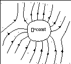
When introducing a conductor into the outer electric field the charges inside the conductor begin to move under the action of forces from the external field until equilibrium is reached. This leads to a redistribution of the electric charge inside the conductor. Regions of the conductor, previously electrically neutral, acquire an uncompensated electric charge. Consequently, an electric field appears (or, as they say, is induced) in the conductor  . The condition for the equilibrium of electric charges:
This allows us to see that the potential difference also has units electric field on distance. This makes sense in a certain way, since it is enough for the difference in electric potential to pass through an electric field. Since the electric field has units of newtons per pendant, we can make the following observation.
If you release a positive charge, which spontaneously accelerates in areas of high potential to low potential - positive charges tend to the minimum electrical potential. In contrast, negative charges seek the maximum electrical potential. Work must be done with positive charges to bring them to greater potential, work to be done with negative charges to take them to areas of lower potential.
 ,
,
those. field strength inside the conductor:
Therefore, from equality we get ![]() inside the conductor. Therefore, this condition is also satisfied at the boundary of the conductor. Those. conductor surface is equipotential
surface
, that's why the lines of force of the electric field are perpendicular to the surface of the conductor at each point
.
inside the conductor. Therefore, this condition is also satisfied at the boundary of the conductor. Those. conductor surface is equipotential
surface
, that's why the lines of force of the electric field are perpendicular to the surface of the conductor at each point
.
For point loads, the electric field is defined through space, except for the right side of the load, and works the same way as its electric potential. There is no obvious place to call "null". Also, we cannot connect the ground wire to a single electron. After all, almost always the potential of a point charge is defined as zero at an infinite distance from the charge itself. This is really handy, believe it or not, and clearly shows that the only way to get rid of the potential due to a point load is to completely expel the load.
charged conductor .
If an external electric charge is imparted to a solitary conductor, then the condition for the equilibrium of charges again leads to the condition:
,![]() inside the conductor.
inside the conductor.
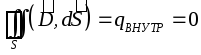
It follows that all external charges are located on the surface of the conductor, since. the field strength inside the conductor is zero, and according to the Gauss theorem for any closed surface inside the conductor (including the outer surface of the conductor):
Figure 3 shows a comparison of the electric field with the electric potential of a point load as a function of distance from the load. Keep in mind: you can only measure differences in electrical potential. A quick point to clear up any confusion later: when talking about point charges like electrons in electric fields or atoms in a crystal, we often use the more convenient unit for energy, the electron volt. As time goes on, we find the electron volt more and more often, and this proves to be very convenient when we are busy calculating a small number of charges.
 .
.
Since the surface of the conductor in this case is also equipotential, the lines of force of the electric field are directed perpendicular to the surface of the conductor at each of its points.
From the Gauss theorem it follows that near the surface of the conductor
The magnitude of the electric displacement vector is equal to the surface density of external charges.
The electric potential also obeys the principle of superposition, as does the electric force. The total electric potential at some point due to several point charges is only the sum of the electric potentials due to the individual point charges. Electric potential is a scalar, we don't have to worry about the components, electric potentials are just the number of their contributions.
As you would expect from the principle of superposition, the potential between two charges is zero, and it becomes very large near each load, as does the electric field. Electric potential in a plane containing an electric dipole. Electric potential height scale. The lines represent equipotential circuits.
The charge on the surface of the conductor is distributed in such a way that the surface potential remains constant. This leads to the fact that the charge density on the surface of the conductor is not the same. For example, on the sharp parts of the conductors, the charge density is greater than in the recesses. In this regard, various phenomena arise, for example, "charge drain". If the conductor is in the air, then ionization of the air occurs near the tip, carrying away part of the electric charge - a phenomenon called "electric wind".
Thus, work on the charge by electric force is associated with a change in the electric potential energy of the charge. Combining these two facts, we can easily relate work and potential difference. In the object of electrostatic theory, we said that for a conductor in electrostatic equilibrium, the net charge is only on the surface of the conductor. On the other hand, we said that the electric field just outside the surface of the conductor is perpendicular to the surface and that the field inside the conductor is zero.
This also means that all points on the surface of a conductor, charged in electrostatic equilibrium, are at the same potential. An arbitrary driver that carries a positive charge. Equation 23 gives us a very general result: there is no work to move a load between two points that have the same electrical potential.
Electrical Imaging Method .
If the equipotential surface is replaced by a conducting surface, and then the part of the field that this surface separates is discarded, then the field pattern in the remaining part will not change. Conversely, if the field picture is supplemented with fictitious charges so that the conducting surface can be replaced by an equipotential one, then the initial field picture will not change.
Because the electric field and displacement are always perpendicular, no work is done when moving across the surface of a conductor. Since the chosen path is completely arbitrary, this means that it is true for any two points on the surface. Potentials and drivers loaded.
The electrical potential is constant at the surface. The electric potential is constant in the interior and has the same value as the value on the surface. No work is required to move the load from the inside to the surface or between two points on the surface.
Example.Find the force of attraction of a point charge to an infinite conducting plane
. To do this, we will supplement the picture with another charge of the same type, but of the opposite sign, located symmetrically with respect to the plane. Then the plane will coincide with the equipotential surface, so the plane can be discarded and the force of interaction between charges can be found: 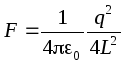 .
.
Of course, this is only true for ideal drivers. If other dissipative forces are present, this is not true and work is required to move the load in the presence of a dissipative force. The electrical analogue of friction or viscosity is resistance.
A surface in which all points are at the same electric potential is called an equipotential surface. The potential difference between two points on the surface is zero, so no work is required to move a load at a constant speed along an equipotential surface. Therefore, the conductor surface is an equipotential surface. Equipotential surfaces have a simple connection with the field: the field is perpendicular to the equipotential surface at all points.
The energy of a charged conductor .
The energy of a solitary charged conductor is defined as the energy of a system of charges:  . On the conductor, so the energy of a solitary conductor:
 .
.
On fig. 10 shows the equipotential surfaces and electric field lines for a single point charge, a dipole, and two equal charges. Note that once you have drawn the electric field lines, drawing equipotential surfaces is trivial and inverse.
Electric field lines are blue lines and red lines are equipotential surfaces for a single point charge, an electric dipole, and two equal charges. How can we really change the electrical potential - generally we'll call it the intensity - of one object in relation to another? Charging by induction or driving is two ways, but a little cumbersome. A device known as a voltage source is a circuit element with two terminals in which a constant potential difference is applied between the two terminals.
For a system of charged conductors:  .
.
In particular, for two conductors having charges q of the same magnitude but different in sign, the energy will be equal to:  .
.
Comment
. The magnitude of the potential difference ![]() called tension
between bodies.
called tension
between bodies.
What is connected to the "negative" terminal of the source will have a voltage below the "positive" terminal. Batteries are an example of a constant voltage source, and wall outlets in your home are another example of a voltage source. Ideal voltage sources are always expressed in the textbook, i.e. they provide a constant potential difference. Real voltage sources always have limitations, primarily the amount of energy that can be generated.
Common Source constant voltage. Now that we know a little about voltage and conductors, we are getting closer to describing simple electrical circuits. We will now introduce our first real circuit element, the capacitor. A capacitor is an electronic component that is used to store electrical charge, it is used in essentially any electrical circuit. Capacitors are the backbone of random access memory and flash memory, and are critical to almost any power supply.
Experience shows that there is a linear relationship between the charge of a solitary conductor and its potential: . Proportionality factor FROM called coefficient of electrical
containers or electrical capacity
.
The unit of electrical capacity is Farad (  ).
).
It is one of the fundamental pillars of electronics. Figure 12 shows a typical capacitor design - two metal plates with a small amount of special material in the middle. It's hard to believe that complex devices like computers are based on such a simple design, but it's true.
When used in a circuit, the plates are connected to the positive and negative terminals of a voltage source such as a battery. The load on both plates is the same, but has the opposite sign. Basically, placing two plates at different potentials means that the electrons want to migrate to the plate with the highest potential and leave the plate with the lower potential. The capacity of this structure. The movement of charge between the plates stops when the potential difference across the plates coincides with the potential difference of the voltage source.
Capacitor is called a system of two conductors charged with the same magnitude, but different in sign charges. The conductors are called capacitor plates .
The capacitance of a capacitor is determined by the formula.
The capacitor is conventionally designated.
Connection of capacitors
The capacitor is sold due to this potential difference and therefore stores electricity until some time later, when it can be claimed for a particular application. You can think of it as storing energy in terms of, or delaying the response as an electrical shock absorber for changing voltage differences.
The capacitance of a particular arrangement of two conductors depends on their geometry and relative arrangement. General structure is a parallel plate capacitor as shown in the figure. In the object of electrostatic theory, we prove the constancy of the electric field between two parallel plates without proof. But what is the field between the plates?
Consider a series connection of two capacitors C 1 and C 2. Point A between the capacitors is separated from the rest of the circuit, so its electrical charge cannot change. Since the initial charge of any point was equal to zero, then ![]() . Consequently, the charges of the capacitor plates adjacent to point A are equal in magnitude, but opposite in sign. But since the value of the charge of the plates is equal to the charge of the capacitors, then. The total charge of point A is zero, so if we discard this point along with the plates, then nothing will change in the circuit. Because the charges of the extreme plates are also the same in magnitude, but different in sign, then the resulting capacitor will have the same charge in magnitude.
. Consequently, the charges of the capacitor plates adjacent to point A are equal in magnitude, but opposite in sign. But since the value of the charge of the plates is equal to the charge of the capacitors, then. The total charge of point A is zero, so if we discard this point along with the plates, then nothing will change in the circuit. Because the charges of the extreme plates are also the same in magnitude, but different in sign, then the resulting capacitor will have the same charge in magnitude.
In Section 8, we find that the electric field over a flat conducting plate is defined as: where is the charge per unit area on the plate. This brings us to a more useful expression for the field: Again, this is not true near the edges of the plates, where the field is not constant. Combining this with the previous facts, we can find the capacitance of a parallel plate capacitor of Equation 24. Capacitance of a parallel plate capacitor.
In Equation 26 we can see that the capacitors can store more charge as the plates get bigger. The same thing happens when the plates get closer. When the plates are closer together, the opposite charges exert a stronger force on each other, allowing more mass to be stored on the plates. From Equation 24, a capacitor of value C in potential difference stores a charge.
TOTAL . The charges of capacitors connected in series are the same in magnitude. The total charge of the capacitors connected in series is equal to the charge of each of the capacitors.
For this case, the total voltage is equal to the sum of the voltages on the capacitors: U GENERAL \u003d U 1 + U 2. The charges of the capacitors are the same: q 1 \u003d q 2 \u003d q. Then 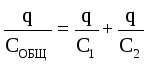 . That's why
 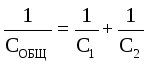 .
.
When capacitors are connected in series, their capacitances are added according to the law of reciprocals .
Capacitance calculation for parallel connection of capacitors.
For this case, the voltages on the capacitors are the same: U 1 \u003d U 2 \u003d U.
The total charge is equal to the sum of the charges: q GEN = q 1 + q 2 or C GEN U=C 1 U+C 2 U.
Then C GENERAL =C 1 +C 2 . When capacitors are connected in parallel, their capacitances add up.
Capacitor energy :
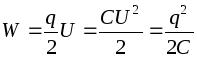 .
.
The total charge of the capacitor is zero. A capacitor stores electrical energy by separating electrical charges.
Examples for calculating the capacitance of capacitors .
Flat (air) condenser represents two parallel plates, the distance between which is much less than the dimensions of the plates, so that the field between the plates can be considered uniform. There is a vacuum (air) between the plates, therefore = 1.
 In this case, when calculating the field pattern, one can use the results obtained for the field of an infinite charged plane. Since the charges and areas of the plates are equal in magnitude, then the magnitude of the field strength created by each of the plates is the same: but the directions of the intensity vectors are different (the intensity vector from a negatively charged plate is shown by a dotted line). Between the plates, the intensity vectors are directed in the same way, so the total intensity is equal to the sum of the field strengths created by each of the plates:
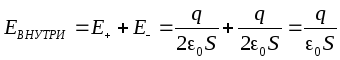 .
.
Outside the plates, the field strength vectors are directed oppositely, so the field strength outside is zero. In this way, in a capacitor, the field strength is nonzero only between the plates.
Since the electrostatic field is a field of conservative force, the integral 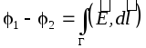 does not depend on the shape of the trajectory G, so the potential difference between the plates can be found along the perpendicular connecting the plates, the length of which is equal to d:
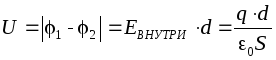 , where d is the distance between the plates. Then the capacitance of a flat (air) capacitor in accordance with the definition will be equal to:
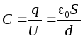
Cylindrical (air) condenser consists of two coaxial cylinders
of the same length, nested in each other so that the distance between the plates is much less than the dimensions of the plates.
Let the length of the capacitor L, the charge of the inner lining is positive: q > 0. Plating radii R 1 and R 2 , let R 1 <R 2. Field strength between the plates at a distance r from the inner lining, i.e. for R 1 <r <R 2 , we find using the Gauss theorem:
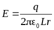 .
.
Then the voltage between the plates: .
Therefore, the electrical capacity of a cylindrical (air) capacitor: 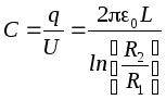 .
.
FROM 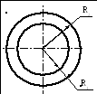 spherical (air) condenser
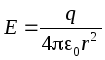
represents two nested concentric spheres with the radii of the plates R 1 and R 2 ,R 1 <R 2. Let the charge of the inner lining q> 0. The field strength between the linings at a distance r from the inner lining ( R 1
<r
<R 2) we find by the Gauss theorem:
spherical (air) condenser
represents two nested concentric spheres with the radii of the plates R 1 and R 2 ,R 1 <R 2. Let the charge of the inner lining q> 0. The field strength between the linings at a distance r from the inner lining ( R 1
<r
<R 2) we find by the Gauss theorem:
 .
.
Tension between plates: .
Therefore, the capacitance of a spherical (air) capacitor 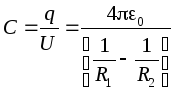 .
.
Volumetric energy density of the electrostatic field.
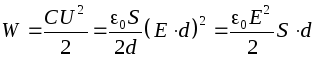
Consider a flat air condenser. Energy of a charged capacitor
 .
.
The amount of space between the plates of a capacitor. Since the field between the plates is considered to be homogeneous, the unit volume of this field has the energy 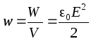 . This value is called volumetric energy density
.
. This value is called volumetric energy density
.
In the case when the field is not uniform, the volumetric energy density is .
In matter, the volumetric energy density of the electric field 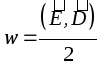 .
.
In the case of a homogeneous isotropic dielectric, therefore 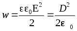 .
.
Because ![]() , then
, then 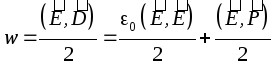 , where
The energy of the electric field in vacuum is the energy of the polarization of matter.
Example . Consider a charged thin-walled sphere of radius R. Since charges of the same name repel each other on the sphere, the repulsive forces tend to stretch the surface of the sphere. We can assume that from inside the sphere, the walls are affected by additional pressure p, bursting the sphere and caused by the presence of an electric charge on the surface. Let's find R.
The field strength inside the sphere is zero, so the volume energy density of the electric field w is different from zero only outside the sphere.
With a slight increase in the radius of the sphere by dR its volume will increase, while in that part of the surrounding space that got inside the sphere, the volumetric energy density will become equal to zero. Therefore, the change in the energy of the field outside will be equal to, where S is the surface area. But with the expansion of the sphere, the pressure forces inside the sphere will do the work ![]() . Since then
. Since then ![]() from where.
from where.
Example . Let's find the forces acting on the plates in a charged flat capacitor, disconnected from the power source.
The plates are oppositely charged, so they attract. Assume that the plates are close to each other by a small amount. x. Then the volume of the condenser is reduced by dV = xS, so the energy of the capacitor has decreased by dW = wdV. Attractive forces do work A = fx. Since A= dW, then fx = wxS. Therefore, the magnitude of the force is F = wS. The additional pressure that these forces create is equal to.
The above examples show that bodies in an electric field are subject to forces that cause additional pressure equal to the volumetric energy density.
The pressure caused by the presence of an electric field is equal to the volumetric energy density .
Forces , acting on the body from the side of some field, are called pondemotor .
The oppositely charged capacitor plates attract each other.
Mechanical forces acting on macroscopic charged bodies are calledponderomotive .
We calculate the ponderomotive forces acting on the plates of a flat capacitor. In this case, two options are possible:
The capacitor is charged and disconnected from the charged battery(in this case, the number of charges on the plates remains constant q = const).
When one plate of a capacitor is removed from the other, work is done
due to which the potential energy of the system increases:
In this case, dA = dW . Equating the right sides of these expressions, we obtain
 (12.67)
In this case, when differentiating, the distance between the plates was designated x.
Capacitor charged but not disconnected from battery(in this case, when moving one of the capacitor plates, the voltage will remain constant ( U = const). In this case, when one plate moves away from the other, the potential energy of the capacitor field decreases, since charges “leak” from the plates, therefore
But 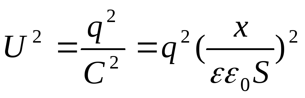 , then
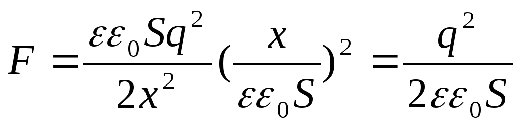
The resulting expression coincides with the formula . It can also be represented in another form if instead of the charge q we introduce the surface density:
 (12.68)
The field is uniform. The field strength of the capacitor is  , where x is the distance between the plates. Substituting into the formula U 2 \u003d E 2 x 2, we get that the force of attraction of the plates of a flat capacitor
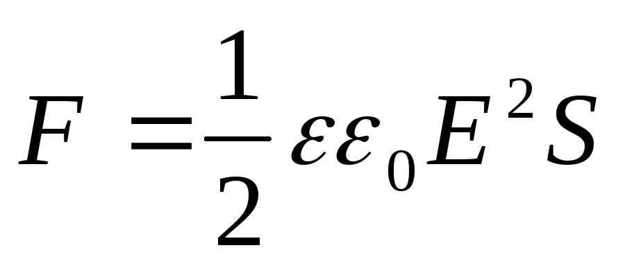 (12.69)
These forces act not only on the plates. Since the plates, in turn, put pressure on the dielectric placed between them and deform it, pressure arises in the dielectric
(S is the area of each plate).
The pressure arising in the dielectric is
 (12.70)
Examples of problem solving
Example 12.5. To flat plates air condenser a potential difference of 1.5 kV is applied. Plate area 150cm 2 and the distance between them is 5 mm. After disconnecting the capacitor from the voltage source, glass was inserted into the space between the plates (ε 2 =7). Define:
1) potential difference between the plates after the introduction of a dielectric; 2) the capacitance of the capacitor before and after the introduction of the dielectric; 3) the surface charge density on the plates before and after the introduction of the dielectric.
Given: U 1 \u003d 1.5 kV \u003d 1.5 ∙ 10 3 V; S \u003d 150cm 2 \u003d 1.5 ∙ 10 -2 m 2; ε 1 =1; d=5mm=5∙10 -3 m.
Find: 1) U 2 ; 2) C 1 C 2; 3) σ 1 , σ 2
Solution
.
Because  (σ is the surface charge density on the capacitor plates), then before the introduction of the dielectric σd \u003d U 1 ε 0 ε 1 and after the introduction of the dielectric σd \u003d U 2 ε 0 ε 2, therefore
The capacitance of the capacitor before and after the introduction of a dielectric
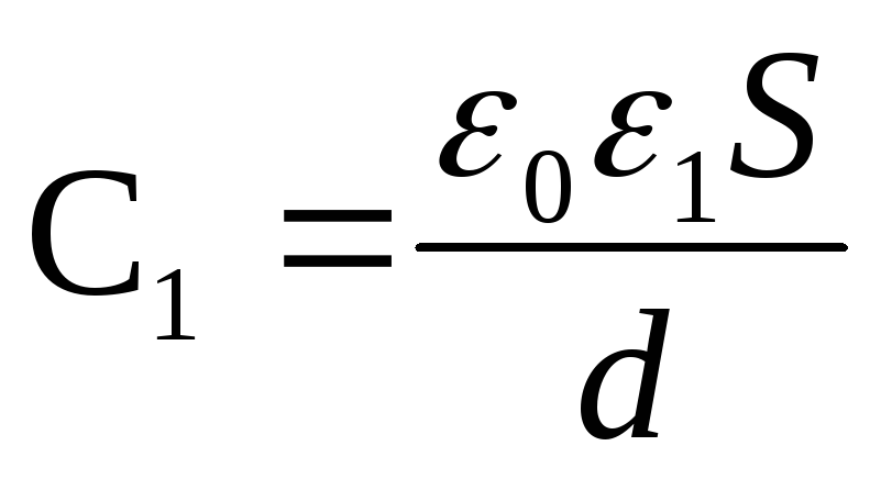 and
and 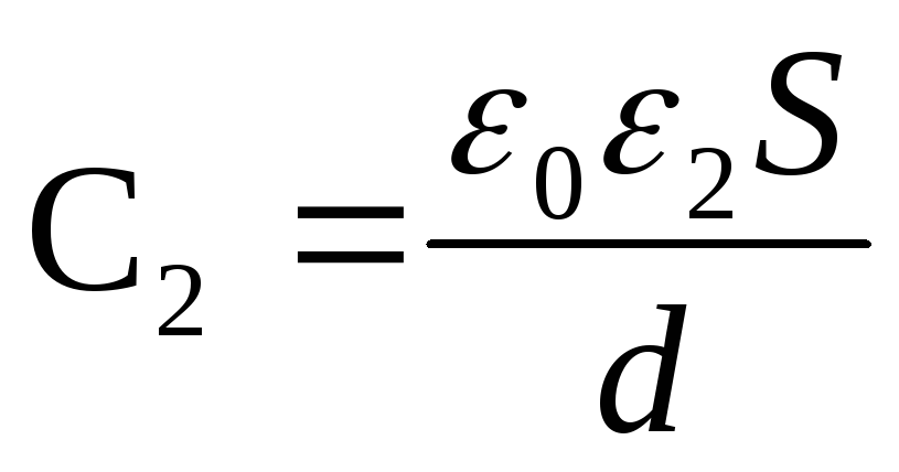
The charge of the plates after disconnection from the voltage source does not change, i.e. q=const. Therefore, the surface charge density on the plates before and after the introduction of the dielectric
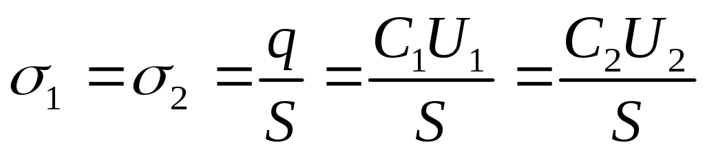
Answer: 1) U 2 \u003d 214V; 2) C 1 \u003d 26.5 pF; C 2 \u003d 186pF; 3) σ 1 = σ 2 = 2.65 μC/m 2.
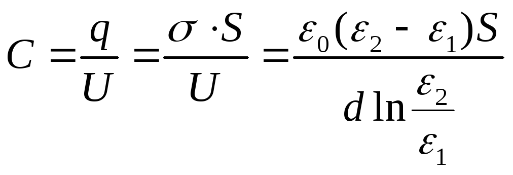
Example 12.7. The gap between the plates of a flat capacitor is filled with an anisotropic dielectric, the permeability ε of which varies in the direction perpendicular to the plates according to the linear lawε = α + βх from ε 1 up to ε 2 , and ε 2 > ε 1 . The area of each liningS, the distance between themd. Find the capacitance of the capacitor.
Given:S; d; ε 1 ; ε 2
Find: FROM.
Solution
.
The dielectric constant ε
varies linearly, ε = α + βx, where x is measured from the lining, whose permeability is equal to ε 1 . Considering that ε (0) = ε 1 , ε (d) = ε 2 , we obtain the dependence 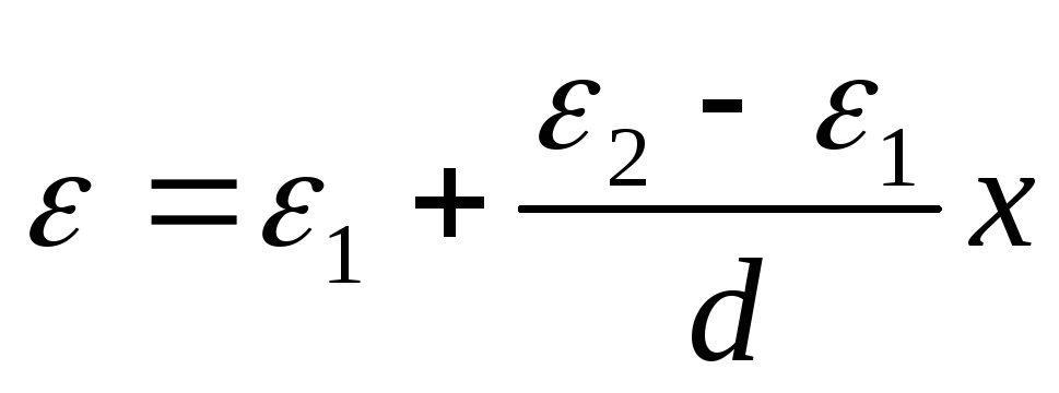 . Find the potential difference between the plates:
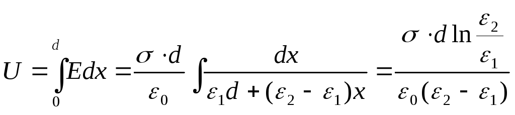
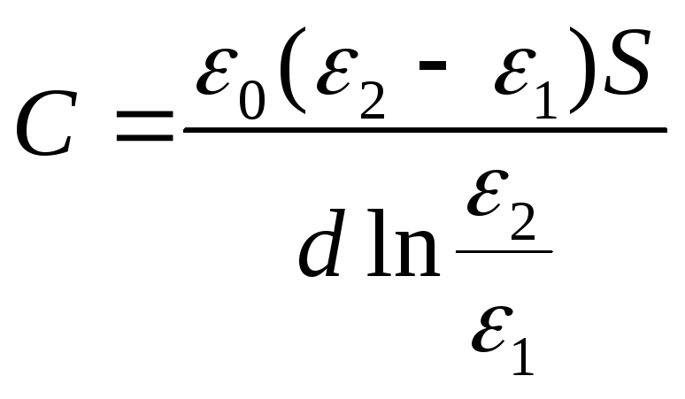
The capacitance of the capacitor will be
Answer:
Example 12.7. Between the plates of a flat capacitor charged to a potential difference U , two layers of dielectrics are placed parallel to its plates. The thickness of the layers and the permittivity of the dielectrics are, respectively,d 1 , d 2 , ε 1 , ε 2 . Determine the strength of electrostatic fields in dielectric layers.
Given: U; d 1 , d 2 , ε 1 , ε 2
Find: E 1 , E 2 .
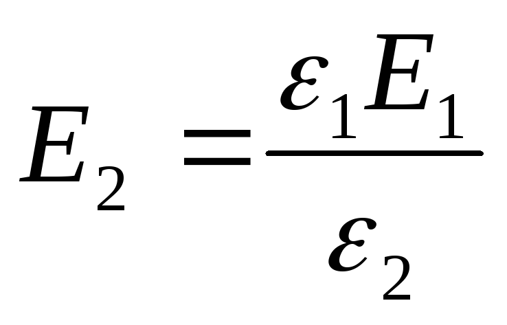
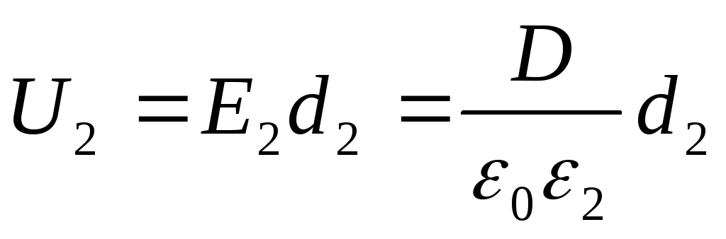
Solution . The voltage across the capacitor plates, given that the field within each of the dielectric layers is uniform,
U=E 1 d 1 +E 2 d 2 . (one)
The electrical displacement in both dielectric layers is the same, so we can write
D=D1=D2= ε 0 ε 1 E 1 = ε 0 ε 2 E 2 (2)
From expressions (1) and (2) we find the desired
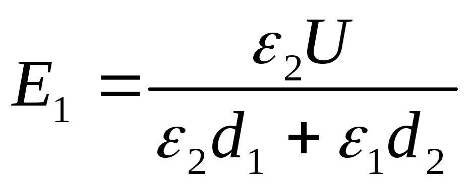 (3)
(3)
From formula (2) it follows that
Answer:
;
Example 12.7. Plate area S flat capacitor is 100cm 2 . The space between the plates is filled closely with two layers of dielectrics - a mica plate (ε 1 =7) thick d 1 =3.5 mm and paraffin (ε 2 =2) thickness d 2 =5 mm. Determine the capacitance of this capacitor.
Given: S=100cm 2 =10 -2 m 2 ; ε 1 =7; d 1 =3.5mm=3.5∙10 -3 m;, ε 1 =2; d 1 =3.5mm=5∙10 -3 m;
Find: FROM.
Solution . Capacitor capacity
where = - charge on the capacitor plates (- surface charge density on the plates); \u003d - potential difference of the plates, equal to the sum of the voltages on the dielectric layers: U \u003d U 1 +U 2. Then
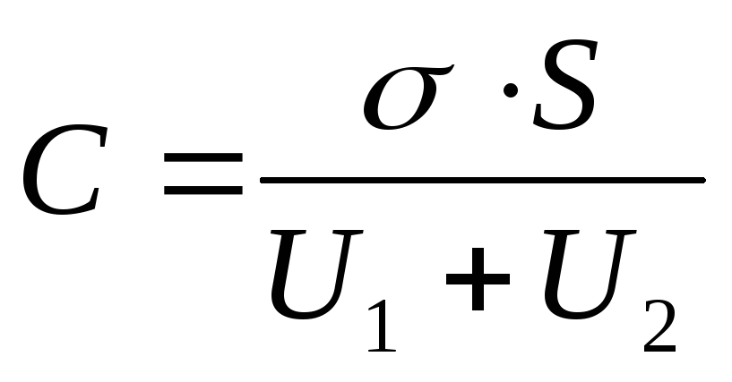 (1)
(1)
The voltages U 1 and U 2 are found by the formulas
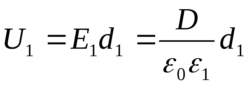 ;
;
 (2)
(2)
where E 1 and E 2 - the strength of the electrostatic field in the first and second layers of the dielectric; D is the electrical displacement in dielectrics (the same in both cases). Taking into account that
And given formula (2), from expression (1) we find the desired capacitance of the capacitor
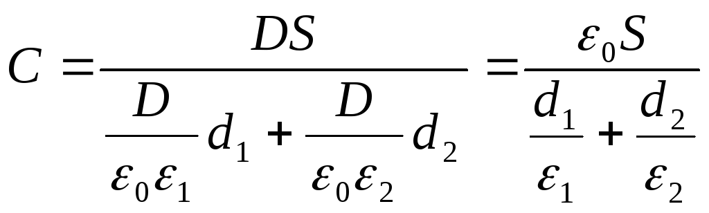
Answer: C \u003d 29.5pF.
Example 12.7. A battery of three capacitors connected in series C 1 \u003d 1 μF; FROM 2 \u003d 2uF and C 3 \u003d 4 μF are connected to an EMF source. Capacitor battery charge q \u003d 40 μC. Determine: 1) voltage U 1 , U 2 and U 3 on each capacitor; 2) EMF source; 3) the capacity of the capacitor bank.
Given : C 1 \u003d 1 μF \u003d 1 ∙ 10 -6 F; C 2 \u003d 2 μF \u003d 2 ∙ 10 -6 F and C 3 \u003d 4 μF \u003d 4 ∙ 10 -6 F; q \u003d 40 μC \u003d 40 ∙ 10 -6 F .
Find: 1) U 1 , U 2 , U 3 ; 2) ξ; 3) C.
Solution . When capacitors are connected in series, the charges of all plates are equal in absolute value, therefore
q 1 \u003d q 2 \u003d q 3 \u003d q.
Capacitor voltage

The EMF of the source is equal to the sum of the voltages of each of the series-connected capacitors:
ξ \u003d U 1 + U 2 + U 3
When connected in series, the reciprocals of the capacitances of each of the capacitors are summed up:
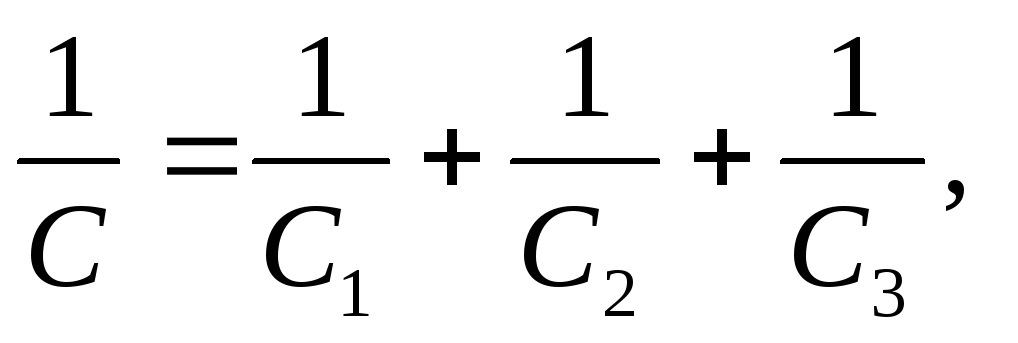
Where is the desired capacity of the capacitor bank
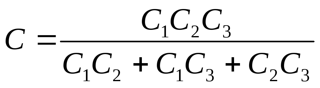
Answer: 1) U 1 \u003d 40V; U 2 \u003d 20V, U 3 = 10V; 2) Ɛ= 70V; 3) C \u003d 0.571 μF.
Example 12.7. Two flat air capacitors of the same capacity are connected in series and connected to an EMF source. How and how many times will the charge of capacitors change if one of them is immersed in oil with a dielectric constant ε=2.2.
Given: C 1 \u003d C 2 \u003d C; q \u003d 40 μC \u003d 40 ∙ 10 -6 F ; ε 1 =1; ε 2 =2,2.
Find:
![]() .
.
Solution . When capacitors are connected in series, the charges of both capacitors are equal in magnitude. Before immersion in a dielectric (in oil), the charge of each capacitor
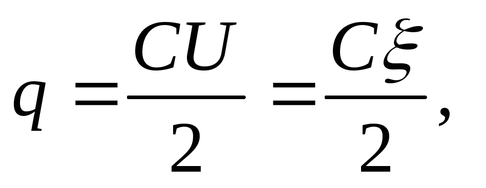
where ξ \u003d U 1 + U 2 (when capacitors are connected in series, the EMF of the source is equal to the sum of the voltages of each of the capacitors).
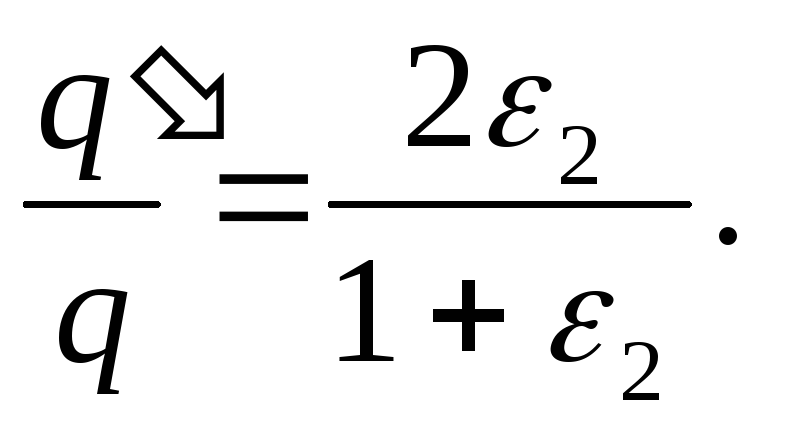
After one of the capacitors is immersed in a dielectric, the charges of the capacitors are again the same and, respectively, on the first and second capacitors are equal
q= CU 1 =ε 2 CU 2
(taking into account that ε 1 =1), whence, if we take into account that ξ = U 1 + U 2 , we find
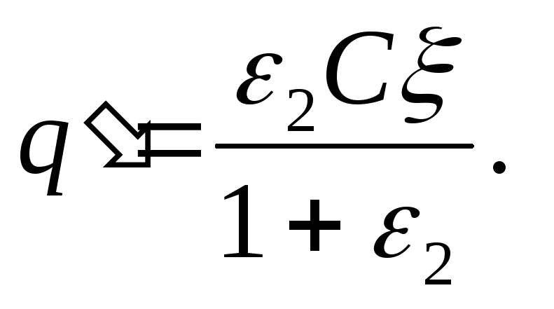 (2)
(2)
Dividing (2) by (1), we find the desired ratio
Answer:
 , i.e. the charge of the capacitors increases by a factor of 1.37.
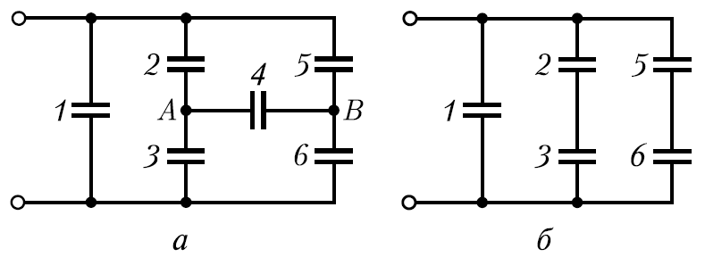
Example 12.7. Capacitors with capacitances C each are connected as shown in fig.a. determine the capacitance common this connection of capacitors. .
 Solution
.
If you disconnect capacitor C 4 from the circuit, you get a connection of capacitors, which is easily calculated. Since the capacities of all capacitors are the same (C 2 \u003d C 3 and C 5 \u003d C 6), both parallel branches are symmetrical, therefore the potentials of points A and B, equally located in the branches, must be equal. Capacitor C 4 is thus connected to points with zero potential difference. Therefore, the capacitor C 4 is not charged, i.e. it can be excluded and the scheme presented in the condition of the problem can be simplified (Fig. b).
Solution
.
If you disconnect capacitor C 4 from the circuit, you get a connection of capacitors, which is easily calculated. Since the capacities of all capacitors are the same (C 2 \u003d C 3 and C 5 \u003d C 6), both parallel branches are symmetrical, therefore the potentials of points A and B, equally located in the branches, must be equal. Capacitor C 4 is thus connected to points with zero potential difference. Therefore, the capacitor C 4 is not charged, i.e. it can be excluded and the scheme presented in the condition of the problem can be simplified (Fig. b).
This circuit consists of three parallel branches, two of which contain two capacitors in series.
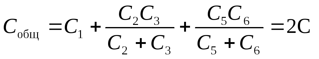
Answer: C total = 2C.
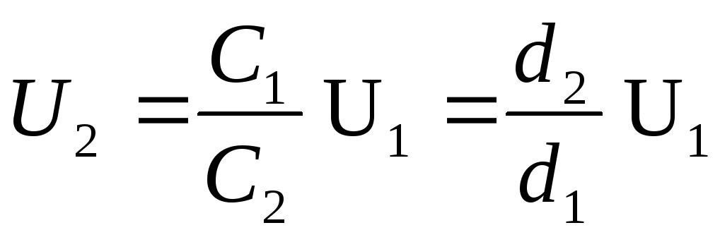
Example 12.7. Flat air condenser with capacity C 1 \u003d 4pF charged to a potential differenceU 1 =100V. After disconnecting the capacitor from the voltage source, the distance between the capacitor plates was doubled. Determine: 1) potential differenceU 2 on the capacitor plates after their separation; 2) the work of external forces to push the plates apart.
Given: C 1 \u003d 4pF \u003d 4 ∙ 10 -12 F; U 1 \u003d 100V; d 2 \u003d 2d 1.
Find: 1) U 2 ;2)A.
Solution . The charge of the capacitor plates after disconnection from the voltage source does not change, i.e. Q=const. That's why
C 1 U 1 \u003d C 2 U 2, (1)
where C 2 and U 2 are, respectively, the capacitance and the potential difference on the capacitor plates after they are moved apart.
Given that the capacitance of a flat capacitor 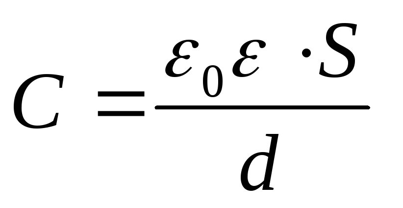 , from formula (1) we obtain the desired potential difference
 (2)
(2)
After disconnecting the capacitor from the voltage source, the system of two charged plates can be considered as closed, for which the law of conservation of energy is satisfied: the work A of external forces is equal to the change in the energy of the system
A \u003d W 2 - W 1 (3)
where W 1 and W 2 are the energy of the capacitor field in the initial and final states, respectively.
Given that ![]() and
and 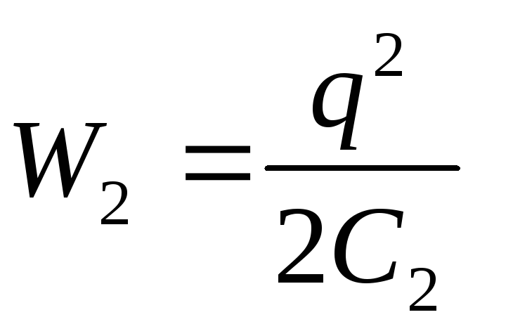 (q – const), from formula (3) we obtain the desired work of external forces
[taken into account that q=C 1 U 1 and formula (2)].
Answer : 1) U 2 \u003d 200V; 2) A \u003d 40nJ.
Example 12.7. A solid ball of dielectric with a radiusR=5cm charged uniformly with bulk density ρ=5nC/m 3 . Determine the energy of the electrostatic field contained in the space surrounding the ball.
Given: R=5cm=5∙10 -2 m; ρ=5nC/m 3 = 5∙10 -9 C / m 3.
Find: W.
Solution . The field of a charged ball is spherically symmetrical, so the volumetric charge density is the same at all points located at equal distances from the center of the ball.
E 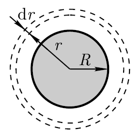 energy in an elementary spherical layer (it is chosen outside the dielectric, where the energy should be determined) with a volume of dV (see figure)
where dV=4πr 2 dr (r is the radius of an elementary spherical layer; dr is its thickness); 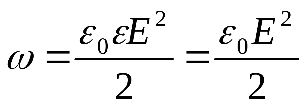 (ε=1 – field in vacuum; E – electrostatic field intensity).
We will find the intensity E by the Gauss theorem for a field in vacuum, and mentally choose a sphere with radius r as a closed surface (see figure). In this case, the entire charge of the ball, which creates the field under consideration, gets inside the surface, and, according to the Gauss theorem,
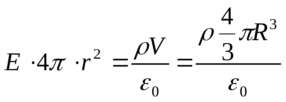
Where 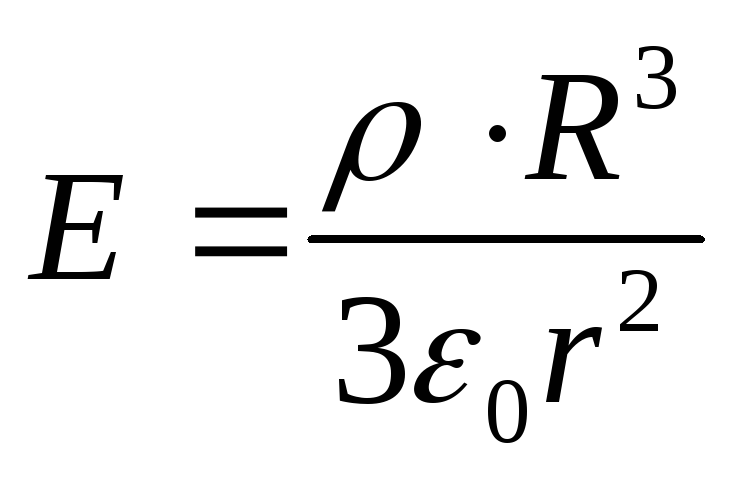
Substituting the found expressions into formula (1), we obtain
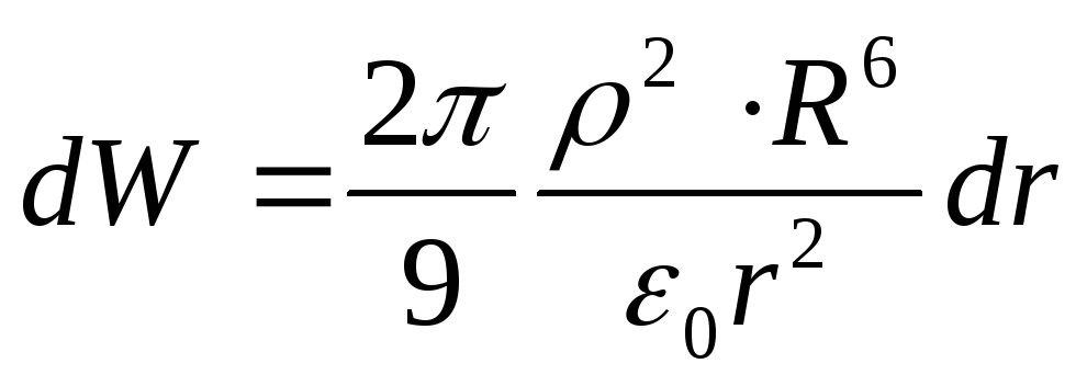
The energy contained in the space surrounding the ball,
Answer: W=6.16∙10 -13 J.
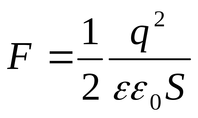
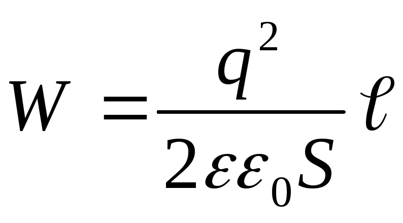
Example 12.7. Planar capacitor with the area of the platesSand the distance between them ℓ the charge is reportedq, after which the capacitor is disconnected from the voltage source. Determine the force of attractionFbetween the capacitor plates, if the dielectric constant of the medium between the plates is equal to ε.
Given : S; ℓ; q; ε .
Find: F.
Solution . The charge of the capacitor plates after disconnection from the voltage source does not change, i.e. q=const. Suppose that under the action of the force of attraction F, the distance between the capacitor plates has changed by d ℓ . Then the force F does work
According to the law of conservation of energy, this work is equal to the energy loss of the capacitor, i.e.
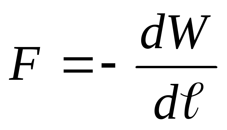 .
(3)
.
(3)
Substituting into the formula for the energy of a charged capacitor  expression for the capacitance of a flat capacitor
 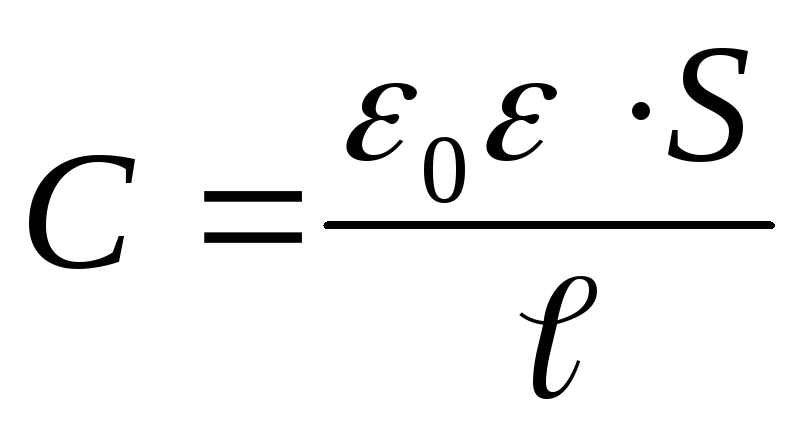 , we get
 (4)
(4)

Answer:
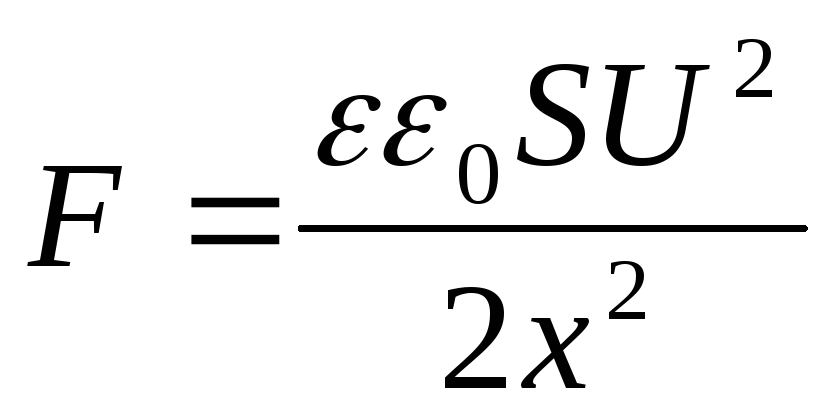
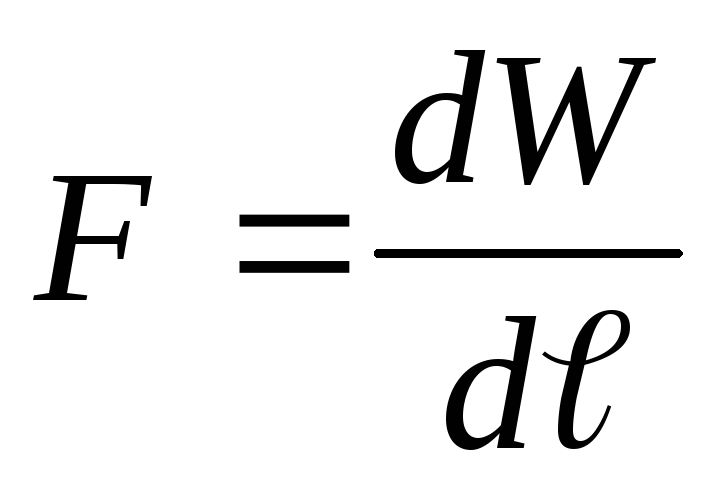
Example 12.7. Flat plate capacitorSand the distance between them ℓ connected to a constant voltage sourceU. Determine the force of attractionFbetween the capacitor plates, if the dielectric constant of the medium between the plates is equal to ε.
Given : S; ℓ; U; ε .
Find: F.
Solution . According to the condition of the problem, a constant voltage is maintained on the capacitor plates, i.e. U=const. Suppose that under the action of the force of attraction F, the distance between the capacitor plates has changed by dℓ. Then the force F does work
According to the law of conservation of energy, this work in this case goes to increase the energy of the capacitor (compare with the previous task), i.e.
whence, based on expressions (1) and (2), we obtain
 (3)
(3)
Substituting into the formula for the energy of the capacitor  expression for the capacitance of a flat capacitor
  , we get
 (4)
(4)
Substituting the energy value (4) into formula (3) and performing differentiation, we find the desired force of attraction between the capacitor plates
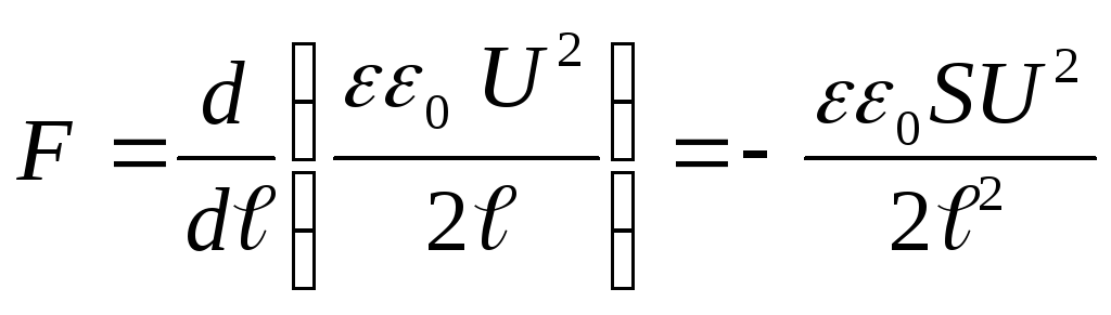 .
.
where the "-" sign indicates that the force F is an attractive force.
Answer
:
We advise you to read
, diagnosis, treatment Treatment of urogenital chlamydia") Chlamydia urogenital - description, causes, symptoms (signs), diagnosis, treatment Treatment of urogenital chlamydia
Chlamydia urogenital - description, causes, symptoms (signs), diagnosis, treatment Treatment of urogenital chlamydia The benefits and significance of hydroamino acid threonine for the human body L threonine what
 To wait or not to wait for a guy from the army For what reason can they be commissioned from the army
 Baked apples with cottage cheese Baked apples with cottage cheese

