I have been repeatedly asked about how to determine the power of a 50Hz unmarked transformer, I will try to tell and show with a couple of examples.
In general, there are quite a few ways to determine the power of a 50Hz transformer, I will list only a few of them.
1. Marking.
Sometimes you can find an explicit indication of power on a transformer, but this indication may not be noticeable at first glance.
The option, of course, is very banal, but you should first look.
2. Overall power of the core.
There are tables by which you can find the overall power of certain cores, but since the cores were produced in a wide variety of size configurations, and besides, they differed in workmanship, the table may not always be correct.
And it's not always easy to find them. However, tables from the descriptions of unified transformers can be indirectly used.
3. Unified transformers.
Even during the union, and indeed after it, a huge number of unified transformers were produced, you can recognize them by the marking starting at the CCI, TN, TA.
If TA is less common, then TPP and TN are very common. 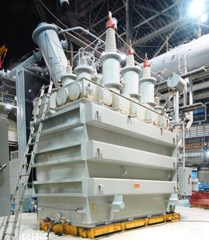
For example, we take the TPP270 transformer. 
We find a description of the marking of this series and in the description we find our transformer, there will be voltages, and currents and power.
I posted this description in the documentation section. By the way, there you can also see the dimensions of the transformer cores and determine the power by its dimensions, comparing it with your own. If your transformer has a slightly larger size, then it is quite possible to recalculate, since the power of the transformer is directly proportional to its size. 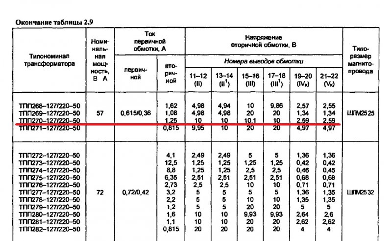
On the TN61 transformer, the marking is almost invisible, but it is there :) 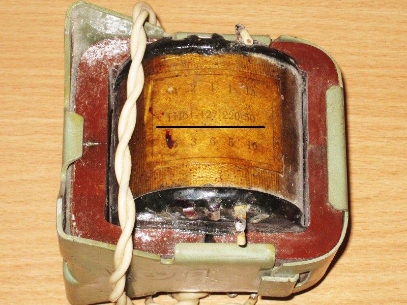
There is a separate description for it, I also have it on my blog. 
Sometimes the transformer is marked, but it is impossible to find anything intelligible on it, alas, tables for such transformers are very rare. 
4. Calculation of power by wire diameter.
If there is no data, then you can determine the power based on the diameter of the winding wires.
It is possible to measure the primary winding, but sometimes it is not available. 
In this case, we measure the diameter of the wire of the secondary winding.
In the example, the diameter is 1.5mm.
Then everything is simple, first we find out the cross section of the wire.
1.5 divided by 2, we get 0.75, this is the radius.
We multiply 0.75 by 0.75, and multiply the resulting result by 3.14 (pi), we get the wire cross section = 1.76mm.kv
The value of the current density is usually taken equal to 2.5 Amperes per 1 mm2. In our case, we multiply 1.76 by 2.5 and get 4.4 Amps.
Since the transformer is designed for an output voltage of 12 volts, we know this, and if we don’t know, we can measure it with a tester, then we multiply 4.4 by 12, we get 52.8 watts.
The paper indicates a power of 60 watts, but now transformers with an underestimated winding cross section are often wound, therefore, by and large, everything converges. 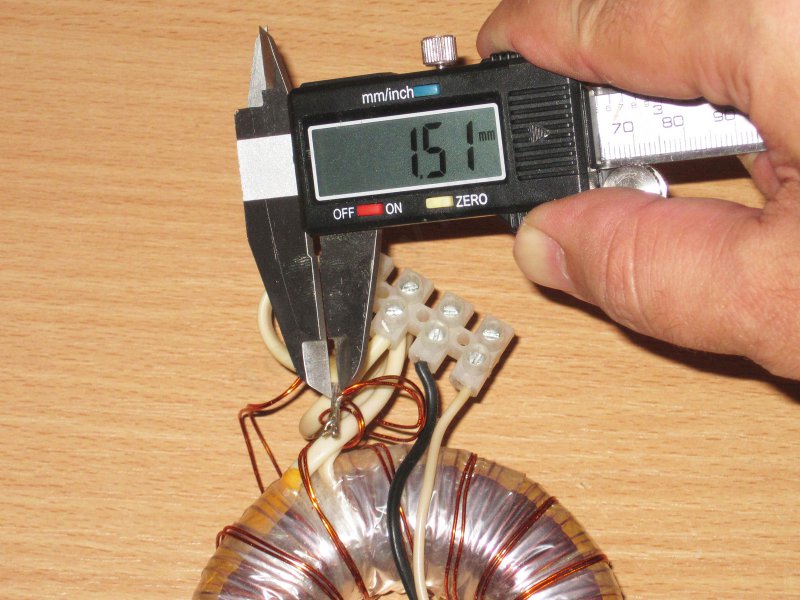
Sometimes on the transformer it is written not only the number of turns of the windings, but also the diameter of the wire. but this should be treated with skepticism, as stickers can be wrong. 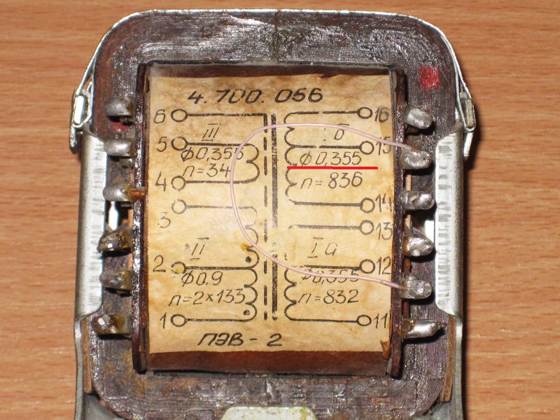
In this example, I first found a section of wire accessible for measurement, raised it a little so that I could crawl with a caliper. 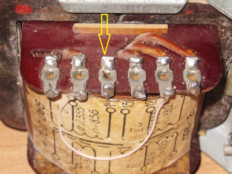
And when I measured it, I found out that the diameter of the wire is not 0.355, but 0.25mm.
Let's try to apply the calculation option that I gave above.
0.25/2=0.125
0.125x0.125x3.14=0.05mm.kv
0.05=2.5=0.122 Amps
0.122x220 (winding voltage) = 26.84 watts.
In addition, the above method is excellent in cases where there are several secondary windings and it is simply inconvenient to measure each. 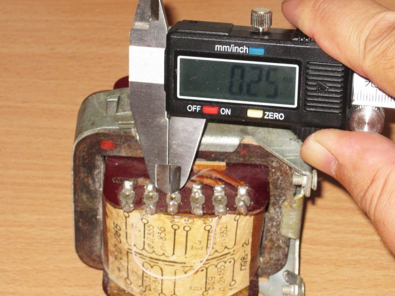
5. Back calculation method.
In some situations, you can use the program to calculate transformers. These programs have a fairly large database of cores, and besides, they can calculate arbitrary size configurations based on what we can measure.
I am using the Trans50Hz program. ![]()
First, choose the core type. Basically, these are options for the annular, W-shaped tape and W-shaped of plates. 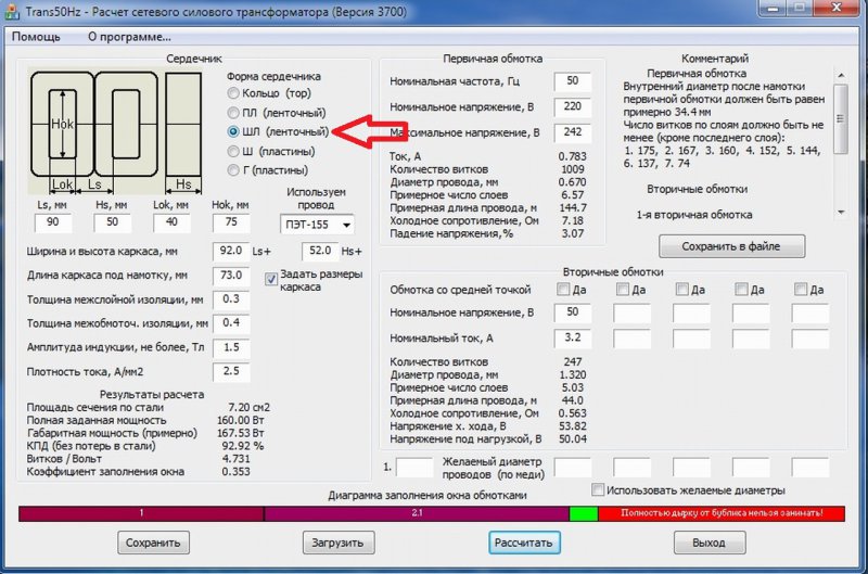
From left to right - Ring, ShL, Sh.
In my example, I will measure the SL option, but you can find out the power of other types of transformers in the same way. 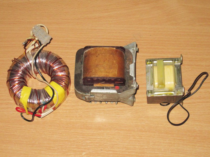
Step 1, measure the width of the side of the magnetic circuit. 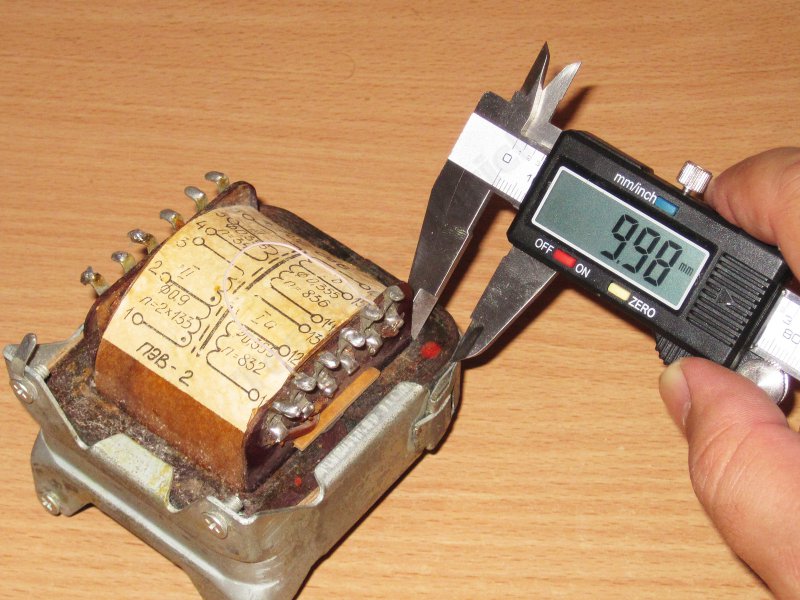
We enter the measured value into the program. 
Step 2, the width of the magnetic circuit. 
Also included in the program. ![]()
Step 3, window width.
There are two options here. If there is access to the window, then we simply measure it. 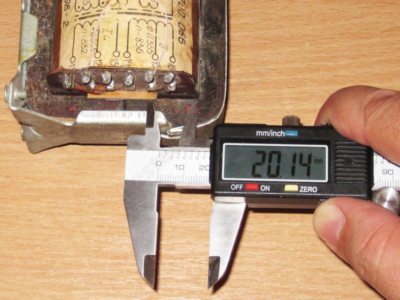
If there is no access, then we measure the total size, then subtract four times the value obtained in step 1, and divide the remainder by 2.
An example is the total width of 80mm, in step 1 it was 10mm, which means we subtract 40 from 80. There are still 40 left, divide by 2 and get 20, this is the width of the window. 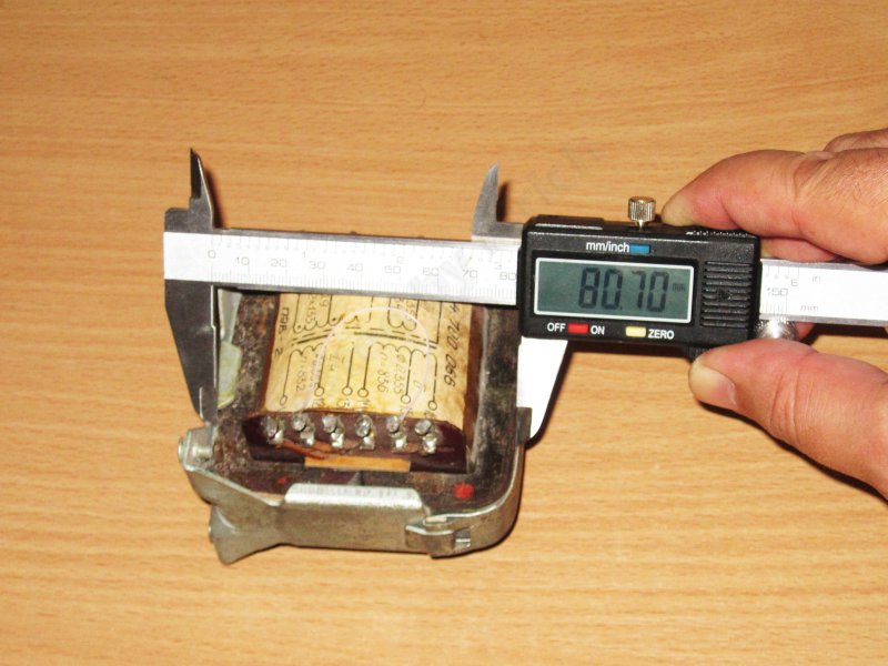
Enter a value. ![]()
Step 4, window length.
In fact, this is the length of the frame for the wire, it can often be measured without problems. 
Also enter this value. ![]()
After that, click on the button - Calculate. 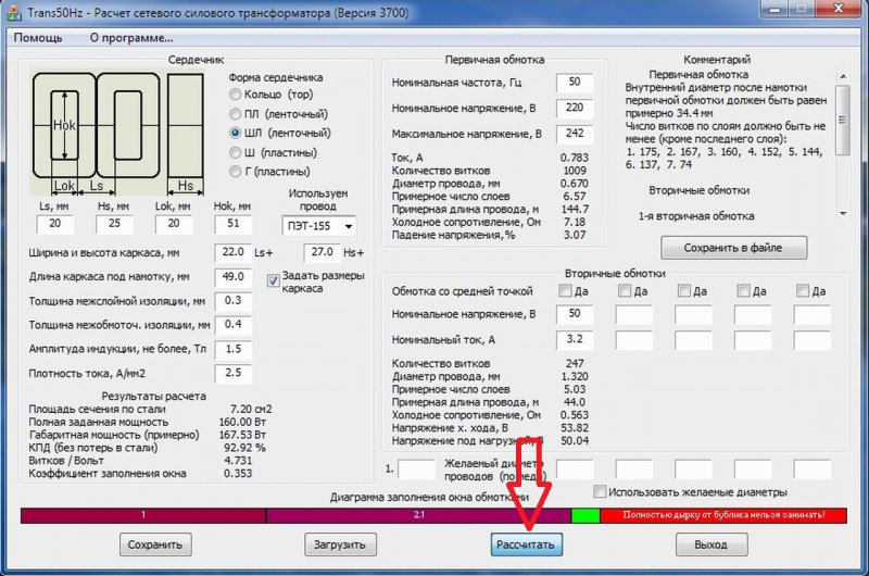
And we get an error message. 
The fact is that the program initially set values for calculating a powerful transformer.
We find the highlighted item and change its value to such that the power (voltage times current) does not exceed our estimated overall power.
You can drive at least 1 Volt and 1 Ampere there, it doesn’t matter, I set 5 Volts. 
We press the Calculation button again and we get the desired result, in this case the program calculated that the power of our magnetic circuit is 27.88 watts..
The data obtained approximately converge with the calculation for the diameter of the wire, then I got 26.84 watts, which means the method works quite well. 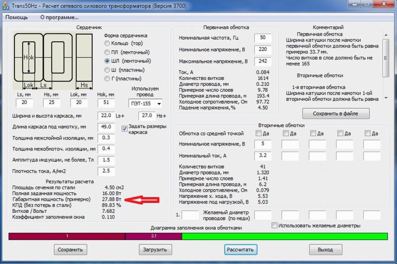
5. Measurement of the maximum temperature.
Ordinary (iron) transformers in operation should not heat up above 60 degrees, this can also be used in power calculations.
But there are exceptions here, for example, an uninterruptible power supply unit transformer can have more power with modest dimensions, this is due to the fact that it works for a short time and it turns off earlier than it overheats. For example, in this embodiment, its power can be 600 watts, and during long-term operation, only 400.
There are also Chinese manufacturers who sometimes use "small-sized" transformers in cheap adapters that heat up like stoves, this is not normal, often the real power of the transformer can be 1.2-1.5 times less than the declared one.
To measure power in the above way, we take any load, light bulbs, resistors, etc. Alternatively, you can use an electronic load, but in this case we connect it through a diode bridge with a filter capacitor.
We wait about an hour, if the temperature does not exceed 60, then we increase the load. Then I think the procedure is clear.
There is really a small caveat, the temperature of the transformer can differ markedly depending on whether there is a case and how big it is, but it gives a very accurate result. The only negative is that the test is very long.
I have rarely used such transformers in the last 10-15 years, because they lie somewhere on the far shelves of the balcony, and when I was looking, I came across very curious indicators, IN-13. I bought it for a level indicator in an amplifier, but in the end I abandoned it. Now I’ve found it and I think what can be done from them, maybe you have ideas and suggestions. When interesting idea, I will try to do and show the process in the form of an overview. 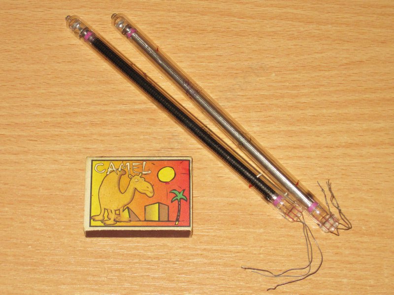
That's all, but as an addition to the video on determining the overall power of the transformer.
Transformers are electromagnetic devices that have two or more inductively coupled windings and are used to determine the value alternating current(voltage). The structure of the device includes a magnetic core with windings placed on it. Single-phase low voltage units are used to power control circuits.
The winding connected to the voltage source is called primary, and those to which current consumers are connected are secondary. Units are divided depending on the result of the work.
Radio amateurs are aware of such a situation when it is necessary to make a transformer that has current and voltage indicators that differ from standard indicators. Sometimes it is possible to find a ready-made device with the required winding parameters, but more often the transformer has to make one's own.
There is a need to calculate the transformer, which in an industrial situation is a complex process, but radio amateurs can calculate their units according to a relatively simplified scheme:
First, they are determined with the values of the parameters at the output of the future device. The optimal rated power is selected, which is calculated by summing the powers of all secondary windings. This indicator on each winding is determined by multiplying the voltage in volts and output current in amperes.
The rated power will allow you to calculate the cross section of the core, obtained in square centimeters. The choice of the core is influenced by the width of its central plate and the thickness of the typesetting layer. To determine the cross section of the core, multiply these two parameters. Power changes as current flows from the primary winding to the secondary. This is due to the magnetic flux in the core, so the size of the core area directly depends on the power indicator.
The optimal type is armor core. If we take for comparison the toroidal or rod type, then one and a half times less wire for the winding device will be required to manufacture the armored one. The toroidal design consists of a ring on which the windings are located, this type has the smallest magnetic radiation of all.
The rod design assumes the presence of two coils with wire winding on each. The windings are divided into two and connected in series. Difficulties arise with determining the direction of the winding; rod types of cores are usually used for powerful transformers. The armored core design is used for small and medium-sized transformers and consists of a single coil with a convenient winding arrangement.
To check if all the windings will fit on the selected unit, use window fill factor. To check it, calculate the area of the window in the core. After that, a coefficient is found showing the number of turns that need to be wound to raise the voltage to a size on the winding of 1 volt.
The number of turns is calculated according to the need for one winding turn per 50 cm2. If you measure the area of \u200b\u200bthe core, then the number of turns is considered to be dividing the resulting area by 50. For example, if the cross-sectional area is 100 cm, then you need to make two turns of the winding per 1 volt.
The calculation of the total number of turns of wire is done by multiplying the amount obtained by 1 volt by the total voltage. For example, 2 turns multiplied by 220, we get 440 turns in one winding. In the loaded mode of operation of the transformer, part of the voltage may be lost to overcome the resistance of the secondary windings. Recommended number of turns determine 5-9% more received in the calculation.
The winding voltage indicator is multiplied by the obtained coefficient, such a calculation is identical for all transformer windings. The operating current indicator is calculated from the parameters of the voltage in the network and the power of the transformer. The resulting operating current value is converted to milliamps and the wire diameter is calculated.
Using a table
To select the optimal indicator for the number of wires, special tables are used that show how the resulting wire diameter is replaced instead of one by two or more identical in terms of joint work.
For example, the value obtained in the calculation is 0.52 mm, therefore, according to the table, it is determined that such an indicator can be changed to two wires of 0.32 mm each or take three wires of 0.28 mm. This means that the wire diameter can consist of several diameters, the total value of which should not be lower than that obtained in the calculation.
Checking the correctness of the choice
Finally, the window fill factor is checked. It should not be higher than 0.5, taking into account the insulation of the wire. If its value is greater, then you need to take a larger section of the core and the whole calculation is done again.
The principle of calculating the transformer online
 This calculation allows quickly change settings, while reducing the time to develop the capacity of the transformer. Initial indicators and data from automatic tables are entered into the fields of different colors. You can correct the data by entering your own indicators. The calculator will allow you to calculate the required wire area and the number of turns in each of the windings.
Data to be entered in the automatic calculator field
Before you can automatically calculate the transformer online, you should define indicators for input:
- voltage in primary winding, usually substitute the value 220 V;
- output voltage of the secondary winding in volts (substitutes data from your requirement);
- output current of the secondary winding in amperes (enter your own value);
- parameters of the outer and inner diameter of the core (set your value);
- specify the height of the core according to its own parameters.
The calculation of the transformer according to the formulas selected from the sources is carried out rather slowly, there is a danger of making mistakes. Online calculation will allow you to design quickly and efficiently. Such a convenient calculation is suitable for beginner radio amateurs, and professionals can use it with no less success. Most fast way make a calculation - enter all the data and click the button.
The most critical and expensive part of the power unit of a radio device powered by an AC mains is a power transformer. One example circuit diagram transformer is shown in fig. 1. The transformer has a core assembled from thin plates of transformer steel. The windings of the transformer are made of insulated copper wire on a pressboard frame.
Transformer cores are assembled from plates of two types: L-shaped and W-shaped. The type of plates also determines the design of transformers, which are shown in fig. 2.
On the rod core (L-shaped plates), the windings of the transformer are placed evenly on both rods (Fig. 2, a), for example, the primary (network) winding and the step-down winding for lamp incandescence are placed on one rod, and the secondary step-up (high-voltage) winding is placed on the other . With this type of plates, windings are sometimes placed on one core rod.
On the armor core (W-shaped plates), all the windings are placed on its middle rod (Fig. 2, b).
If we connect the primary winding I of the transformer to an alternating current source (Fig. 3), an alternating current will flow through it, which will create an alternating magnetic flux in the core. Since the secondary winding II is located on the second rod of the transformer, the alternating magnetic flux will cross the turns of the secondary winding, as a result of which (according to the law of electromagnetic induction) it will be induced electromotive force(EMF). If a device (voltmeter) is connected in parallel with the secondary winding, it will show the magnitude of the induced voltage.
In order to lower the mains voltage, the secondary winding must have fewer turns than the mains, and to increase the voltage - more than the primary (mains) winding.
Various voltages are required to power the radio equipment: a high voltage (with subsequent rectification) for powering the anode circuits and circuits of the screen grids of lamps and two low voltages for powering the filament circuits of the lamps and separately for heating the kenotron if it is used in a rectifier (the only exception is the 6Ts5S kenotron, the thread the filament of which can be powered from a common filament winding).
Due to losses in the core and windings, the same power can never be obtained from the secondary winding of a transformer as was supplied to the primary winding. Hence there is the concept of efficiency (efficiency) of the transformer. Home-made transformers, calculated according to simplified formulas and made on ordinary transformer steel, usually have an efficiency above 70-80%.
Suppose that the transformer must provide power to an amplifier or receiver that consumes a current of 100 mA at a voltage of 250 V through the anode circuits and a current of 2 A at a voltage of 6.3 V through the filament circuit. 2 a at a voltage of 5 V (to determine the currents consumed by the electrodes of a particular lamp, you should use their reference data).
Thus, with a large approximation (without taking into account the voltage drop across internal resistance kenotron and filter inductor) the secondary winding must be rated for a voltage of 250 V and a current of 100 mA (0.1 A), the lamp filament winding for a voltage of 6.3 V and a current of 2 A, and the kenotron filament winding for 5 V and current 2 A. We calculate their power according to the formula
where U is in volts and I is in amps. Therefore, P1=250*0.1=25W, P2=5*2=10W, P3=6.3*2=12.6W.
P sat = P1 + P2 + P3 ... W (2)
The power in all three secondary windings will be equal to
R sb \u003d 25 + 10 + 12.6 \u003d 47.6 W.
If we take the efficiency of a transformer made in amateur conditions, not higher than 80%, the power consumed from the network can be calculated by the formula
R lane \u003d 1.2 * R sb. (3)
In our case, the power consumed from the network will be equal to
R pr \u003d 1.2 * 47.6 \u003d 57.12 W.
The next stage of the calculation is the determination of the cross section of the core, t, e core area in square centimeters - Q cm 2. It is calculated according to the formula
Qcm 2 \u003d 1.2 * P lane 0.5 \u003d cm 2. (4)
Since the core is assembled from thin plates isolated from each other, a factor of 1.2 is introduced into the formula, taking into account the filling of the core. Thus, the cross section of the core of our transformer will be equal to
Q cm 2 \u003d 1 * 2 57.12 0.5 \u003d 9.07 cm 2
(we consider rounded 9.0 cm 2).
After that, you need to determine the width of the plates of the middle rod (if the plates are W-shaped) and the thickness of the set in cm. Multiplying these values, we get the cross-sectional area of \u200b\u200bthe rod. Since the calculation of all the geometric dimensions of the core (window area, set thickness and plate width) for a beginner radio amateur is a rather complicated matter, you can simply consider the ratio of the width of the rod plates to the set thickness to be from 1 to 2.
Table 1
With this ratio, you can be sure that the number of turns obtained from further calculation will fit into the core window. From the table. 1 data, we select Sh-25 plates, at which the thickness of the set will be 3.6 cm, and the aspect ratio will be 1.44, since 9 cm 2: 2.5 cm = 3.6 cm, and 3.6: 2, 5 = 1.44.
n0 = (45 - 60)/Q = turns, (5)
where Q is the cross section of the core in cm 2. If there are transformer steel plates good quality, the number 45 should be substituted into the numerator, if the steel is bad - 60. When calculating, we assume that the core is taken from the factory transformer, then the number of turns per volt will be equal to
Further calculation of the windings is no longer any difficulty, you just need to multiply the number of turns per volt by the given voltage of one or another winding. The primary winding for connection to a network with a voltage of 127 V must have P1 = 127x5 = 635 turns, increasing by 250 V - P2 = 250x5 = 1250 turns, for heating the kenotron 5 V - P3 = 5x5 = 25 turns and for heating lamps 6.3 B - P4 \u003d 6.3x5 \u003d 31.5 turns (round up to 32 turns).
The last step in the calculation of the windings is the determination of the diameter winding wire according to a formula that provides for a long-term, uninterrupted load of the transformer, at which the current density (strength) per one square millimeter wire cross section is taken no more than two amperes,
d = 0.8*I 0.5 = mm, (6)
where d is the wire diameter in millimeters, I is the current in amperes.
In our case, d2 \u003d 0.8 * 0.1 0.5 \u003d 0.8x0.316 \u003d 0.25 mm; d3 \u003d d \u003d 0.8 * 2 0.5 \u003d 8x1.41 \u003d 1.1 mm (rounded).
I1 \u003d 57.12 / 127 \u003d 0.45 A (rounded),
hence d1 = 0.8 * 0.45 0.5 = 0.54 mm, or, rounded, 0.55 mm.
For greater certainty, you can check whether the windings will fit in the window of the core we have chosen. It is done like this. From Table. 1 shows that the length of the window of the core plate is 6 cm, and the width is 2.5 cm, but since the windings are wound on a frame that takes up a lot of space in the window, these dimensions should be reduced by the thickness of the cheeks of the frame and the thickness of the sleeve. As a result, the length of the window will be approximately 5.2 cm, and the width will be 2.2 cm. According to the table. 2 we find that the wires of the windings in enamel insulation will have the following outer diameters: d1 = 0.59 mm, d2 = 0.27 mm, d3 = d4 = 1.15 mm.
table 2
| Wire diameter without insulation, mm |
Insulated wire diameter, mm |
||||
| PEL | PSHO | PSHD | PBO | PBB | |
| 0,1 | 0,115 | 0,15 | 0,2 | 0,19 | - |
| 0,15 | 0,165 | 0,2 | 0,25 | 0,24 | - |
| 0,2 | 0,215 | 0,26 | 0,32 | 0,29 | 0,37 |
| 0,25 | 0,27 | 0,31 | 0,37 | 0,34 | 0,42 |
| 0,31 | 0,33 | 0,37 | 0,43 | 0,42 | 0,51 |
| 0,35 | 0,38 | 0,41 | 0,47 | 0,46 | 0,55 |
| 0,41 | 0,44 | 0,47 | 0,53 | 0,52 | 0,61 |
| 0,44 | 0,475 | 0,5 | 0,56 | 0,55 | 0,64 |
| 0,51 | 0,545 | 0,57 | 0,63 | 0,62 | 0,71 |
| 0,55 | 0,59 | 0,61 | 0,67 | 0,66 | 0,75 |
| 0,64 | 0,68 | 0,7 | 0,76 | 0,75 | 0,84 |
| 0,8 | 0,85 | - | - | 0,91 | 1,00 |
| 1,0 | 1,05 | - | - | 1,125 | 1,25 |
| 1,2 | 1,26 | - | - | 1,325 | 1,45 |
Thus, in one layer of a wire with a diameter of 0.59, 52 / 0.59 \u003d 88 turns will fit, and the number of layers of this winding will be equal to
685/88 = 7 (rounded). Over the width of the window, the layers will take 7x0.59 = 4.2 mm, or 0.42 cm.
For a wire with a diameter of 0.27 (with insulation), the number of turns in the layer will be 2 / 0.27 \u003d 192. Accordingly, we get the number of layers 6.5, we count seven layers with a margin. They will take 2 mm, or 0.2 cm, across the window width.
The number of turns in a wire layer with a diameter of 1.15 is 52 / 1.15 = 45. Thus, the filament windings will fit into two layers, which will take 2.3 mm, or 0.23 cm across the window width.
Adding the obtained values \u200b\u200bof 0.42 + 0.2 + 0.23, we get that all windings along the width of the window will take 0.85 cm.
In our calculation, we did not foresee that the lead ends of the windings, the spacers between the layers of cigarette or capacitor paper and the spacers between the windings of varnished fabric or several layers of cable paper will take up much space.
It should be noted that novice radio amateurs will not be able to immediately tightly and accurately, turn to turn, wind the windings. Therefore, we will assume that the windings in the window will take not 0.85 cm, but 1 cm. If, when calculating, it turns out that the windings in the window do not fit, then you should take larger plates or increase the thickness of the plate package. Thus, it will be possible to reduce the number of turns of the windings by one volt.
For the manufacture of a transformer, a pressboard, fiber or getinax with a thickness of 1.5-2 mm is also needed. To isolate the windings from each other and between the layers of the windings, you will need varnished cloth, cable or, in extreme cases, ordinary writing paper. Varnished cloth, which has high insulating properties, can be replaced with several layers of drawing tracing paper.
The manufacture of the transformer coil begins with the manufacture of a wooden blank for the frame, the sides of which should be slightly larger (by 0.5 mm) than the sides of the core rod, and its length is 1.5-2 cm longer than the length of the transformer rod.

Drive a nail without a hat into the center of the wooden blank, as shown in fig. 4.
After that, they begin to manufacture a frame from pressboard or getinaks of a specified thickness, on which the marking of the sides of the sleeve and the cheeks of the frame is made, as shown in Fig. 5. The length of the frame should be slightly less than the length of the rod (by 1-2 mm).

Despite the fact that such a frame is made without glue, it has great strength when carefully executed. The assembled frame (Fig. 5) is put on the blank, and if it does not adhere tightly to it, a strip of cardboard should be laid between the frame and the blank or the blank should be wrapped with several layers of paper.
If the radio amateur has a drill and a vise, winding the transformer coil is not very difficult. In a vice, you need to clamp the drill in a horizontal position, into the cartridge of which to clamp the nail of the blank. When the drill rotates, the sleeve should in no case beat due to distortions or eccentricity, since the turns will lie incorrectly, which will complicate the winding process, worsen its quality, as a result of which the winding will take up much more space. After the frame is fixed in the drill chuck, strips of paper, varnished cloth or other insulating material should be prepared, the width of which should be 4-5 mm more distance between the cheeks of the sleeve.
![]()
The conclusions of the windings (with the exception of the filament windings) should in no case be made with the same wire, but with stranded wire, well insulated wire 10-12 cm long, to which the winding wire is soldered. The place of soldering must be well insulated by wrapping it with a piece of varnished cloth, strengthening the coil with wire, as shown in fig. 6, and start winding.
When winding, it is recommended to rotate the handle of the drill with your right hand, and put the elbow of your left hand on the table so that the fingers holding the wire are at a distance of 20-30 cm in front of the frame. In this way, it is easier to wind a turn to a turn (the turns are less likely to go astray).
If the radio amateur does not have a counter, then after winding each layer, the number of turns in the layer should be counted and the result recorded.
You can also count the turns. First, determine how many revolutions the drill chuck makes per revolution of the handle, and record the number of revolutions made, having previously multiplied by the resulting ratio. For example: for one turn of the drill handle, the cartridge makes 3.8 turns, therefore, for 100 turns made by hand during winding, 380 turns will be wound.
Each layer of the wound winding should be laid with a prepared strip of paper and carefully ensure that the last turns of each layer do not fall between the cheek into the lower layer, since insulation breakdown between layers is possible in this place, which can be explained as follows. In our calculation, it turned out that there are 5 turns per volt, and 192x2 = 384 turns fit in two layers of the high-voltage winding, therefore, the effective voltage acting between the two layers will be 386/5, or 77 V, and the amplitude voltage will be 108 B, that when the windings are heated, it can lead to a breakdown of the insulation.
Before winding the secondary windings, primarily high-voltage winding, two layers of varnished cloth or two or three layers of cable paper should be placed on top of the primary winding. All windings must be well insulated from each other.
The output ends of the windings should be located on one side of the cheeks of the coil, otherwise they are easy to spoil when stuffing the coil, especially if the plates are made with a notch, as shown in fig. 7. For stuffing with steel plates, the coil is placed on the table, after which one half of the plates is placed on the right side of the coil, and the other on the left. The stuffing is carried out in overlap, i.e. one plate is pushed into the coil from the right side, and the other from the left. Usually finished plates are varnished on one side, so when stuffing the coil, you need to make sure that the varnished sides of the plates are always turned up or down. The packing of the plates must be carried out with maximum density, for which, before the end of the packing, the core should be pressed by compressing it in a vice, and then even more plates can be inserted.
The assembled transformer core should be knocked out from all sides with a hammer so that all the plates lie down in an even pile, and then pull the core with pins.
The manufactured transformer should be tested by connecting it to the mains. If after one or two hours the windings do not heat up, then the transformer is designed and made correctly.
The heating of the winding can be explained by the presence of closed turns (sloppy winding). Before turning on the transformer, it is necessary to check that the output ends of the winding do not accidentally close to each other. Chattering of the core plates indicates a loose assembly. In this case, you need to insert a few more pieces of plates into the core and tighten the locks on the studs more tightly. If the radio amateur has an AC voltmeter or an avometer, the voltages on all secondary windings should be checked.
Calculation power transformer
A transformer is a passive energy converter. Its coefficient of performance (COP) is always less than one. This means that the power consumed by the load, which is connected to the secondary winding of the transformer, is less than the power consumed by the loaded transformer from the mains. It is known that the power is equal to the product of the current strength and voltage, therefore, in the step-up windings, the current strength is less, and in the step-down windings, it is more than the current consumed by the transformer from the network.
Parameters and characteristics of the transformer.
Two different transformers at the same mains voltage can be designed to receive the same secondary winding voltages. But if the load of the first transformer consumes more current, and the second one is small, then the first transformer is characterized in comparison with the second by more power. The greater the current strength in the transformer windings, the greater the magnetic flux in its core, so the core must be thicker. In addition, the greater the current in the winding, the thicker the wire it must be wound, and this requires an increase in the core window. Therefore, the dimensions of the transformer depend on its power. Conversely, a core of a certain size is suitable for the manufacture of a transformer only up to a certain power, which is called the overall power of the transformer. The number of turns of the secondary winding of the transformer determines the voltage at its terminals. But this voltage also depends on the number of turns of the primary winding. At a certain value of the supply voltage of the primary winding, the voltage of the secondary depends on the ratio of the number of turns of the secondary winding to the number of turns of the primary. This ratio is called the transformation ratio. If the voltage on the secondary winding depends on the transformation ratio, it is impossible to arbitrarily choose the number of turns of one of the windings. The smaller the dimensions of the core, the greater should be the number of turns of each winding. Therefore, the size of the core of the transformer corresponds to a well-defined number of turns of its windings per one volt of voltage, less than which cannot be taken. This characteristic is called the number of turns per volt.
Like any energy converter, a transformer has an efficiency factor - the ratio of the power consumed by the transformer load to the power that the loaded transformer consumes from the network. The efficiency of low-power transformers, which are usually used to power consumer electronic equipment, ranges from 0.8 to 0.95. Larger power transformers have higher values.
Electrical calculation of the transformer
Before calculating the transformer, it is necessary to formulate the requirements that it must satisfy. They will be the initial data for the calculation. The technical requirements for the transformer are also determined by calculation, as a result of which the voltages and currents that must be provided by the secondary windings are determined. Therefore, before calculating the transformer, the rectifier is calculated to determine the voltages of each of the secondary windings and the currents consumed from these windings. If the voltages and currents of each of the transformer windings are already known, then they are the technical requirements for the transformer. To determine the overall power of the transformer, it is necessary to determine the power consumed from each of the secondary windings and add them, also taking into account the efficiency of the transformer. The power consumed from any winding is determined by multiplying the voltage between the terminals of this winding by the strength of the current consumed from it:
P is the power consumed from the winding, W;
U is the effective value of the voltage taken from this winding, V;
I is the effective value of the current flowing in the same winding, A.
The total power consumed, for example, by three secondary windings, is calculated by the formula:
P S \u003d U 1 I 1 + U 2 I 2 + U 3 I 3
To determine the overall power of the transformer, the resulting value of the total power P S must be divided by the efficiency of the transformer: P g = , where
P g - overall power of the transformer; η is the efficiency of the transformer.
It is impossible to calculate the transformer efficiency in advance, since for this you need to know the amount of energy loss in the windings and in the core, which depend on the parameters of the windings themselves (wire diameters and their length) and the core parameters (length of the magnetic field line and steel grade). Both those and other parameters become known only after the calculation of the transformer. Therefore, with sufficient accuracy for practical calculation, the efficiency of the transformer can be determined from Table 6.1.
Table 6.1
|
Total power, W | ||||
|
transformer efficiency |
The most common are two forms of the core: O - shaped and W - shaped. There are usually two coils on the O-shaped core, and one coil on the W-shaped core. Knowing the overall power of the transformer, they find the cross section of the working core of its core, on which the coil is located:
The cross section of the working core core is the product of the width of the working core a and the thickness of the package c. Dimensions a and c are expressed in centimeters, and the cross section is expressed in square centimeters.
After that, the type of transformer steel plates is selected and the thickness of the core package is determined. First, find the approximate width of the working core core according to the formula: a= 0.8
Then, according to the obtained value a, the type of transformer steel plates is selected from among those available and the actual working core width a is found. after which the thickness of the core package is determined with:
The number of turns per 1 volt of voltage is determined by the cross section of the working core of the transformer core according to the formula: n \u003d k / S, where N is the number of turns per 1 V; k is the coefficient determined by the properties of the core; S is the cross section of the working core of the core, cm 2.
From the above formula it can be seen that the smaller the coefficient k, the fewer turns all transformer windings will have. However, the coefficient k cannot be chosen arbitrarily. Its value usually ranges from 35 to 60. First of all, it depends on the properties of the transformer steel plates from which the core is assembled. For C-shaped cores, twisted from a thin tape, you can take k = 35. If an O-shaped core is used, assembled from U- or L-shaped plates without holes in the corners, take k = 40. The same value k for USh type plates , in which the width of the side cores is more than half the width of the middle core. = 50. Thus, the choice of k is largely conditional and can be varied within certain limits, given that a decrease in k facilitates winding, but tightens the transformer mode. When using plates made of high-quality transformer steel, this coefficient can be slightly reduced, and when the quality of steel is low, it has to be increased.
Knowing the required voltage of each winding and the number of turns per 1 V, it is easy to determine the number of turns of the winding, multiply these values: W = Un
This ratio is valid only for the primary winding, and when determining the number of turns of the secondary windings, it is necessary to additionally introduce an approximate correction to take into account the voltage drop on the winding itself from the load current flowing through its wire: W = mUn
The coefficient m depends on the strength of the current flowing through a given winding (see table 6.2). If the current strength is less than 0.2 A, m = 1 can be taken. The thickness of the wire with which the transformer winding is wound is determined by the strength of the current flowing through this winding. The greater the current, the thicker the wire must be, just as a thicker pipe is required to increase the flow of water. The resistance of the winding depends on the thickness of the wire. The thinner the wire, the greater the resistance of the winding, therefore, the power released in it increases and it heats up more. For each type of winding wire there is a limit of permissible heating, which depends on the properties of the enamel insulation. Therefore, the diameter of the wire can be determined by the formula: d \u003d p, where d is the diameter of the wire for copper, m; I is the current in the winding, A; p is the coefficient (table 6.3) which takes into account the allowable heating of a particular brand of wire.
Table 6.2: Factor definition m
Table 6.3: Selection of wire diameter.
|
Wire brand | ||||
By choosing the coefficient p, you can determine the diameter of the wire of each winding. The found value of the diameter is rounded up to a larger standard.
The current strength in the primary winding is determined taking into account the overall power of the transformer and the mains voltage:
Practical work:
U 1 = 6.3 V, I 1 = 1.5 A; U 2 = 12 V, I 2 = 0.3 A; U 3 = 120 V, I 3 = 59 mA
Determining the power of a power transformer
 How to find out the power of a transformer?
For the manufacture of transformer power supplies, a single-phase power transformer is required, which lowers AC voltage mains 220 volts to the required 12-30 volts, which is then rectified by a diode bridge and filtered by an electrolytic capacitor. These transformations electric current necessary, since any electronic equipment is assembled on transistors and microcircuits, which usually require a voltage of no more than 5-12 volts.
To assemble the power supply yourself, a beginner radio amateur needs to find or purchase a suitable transformer for the future power supply. In exceptional cases, you can make a power transformer yourself. Such recommendations can be found on the pages of old books on radio electronics.
But nowadays it's easier to find or buy a ready-made transformer and use it to make your own power supply.

Full account and independent production a transformer for a beginner radio amateur is a rather difficult task. But there is another way. You can use a used, but serviceable transformer. To power most home-made designs, a low-power power supply with a power of 7-15 watts is enough.
If the transformer is purchased in a store, then, as a rule, there are no special problems with the selection of the desired transformer. The new product has all its main parameters, such as power, input voltage, output voltage, as well as the number of secondary windings, if there is more than one.
But if you got a transformer that has already worked in some device and you want to reuse it to design your power supply? How to determine the power of a transformer at least approximately? The power of the transformer is a very important parameter, since the reliability of the power supply unit or other device you have assembled will directly depend on it. As you know, the power consumed by an electronic device depends on the current it consumes and the voltage that is required for its normal operation. Approximately this power can be determined by multiplying the current consumed by the device ( I n to the supply voltage of the device ( U n). I think many people are familiar with this formula from school.
P=U n * I n
Where U n- voltage in volts; I n- current in amperes; P- power in watts.
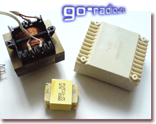
Consider the definition of the power of the transformer on a real example. We will train on the transformer TP114-163M. This is an armor type transformer, which is assembled from stamped W-shaped and straight plates. It should be noted that transformers of this type are not the best in terms of efficiency (efficiency). But the good news is that such transformers are widespread, often used in electronics and are easy to find on the shelves of radio stores or in old and faulty radio equipment. In addition, they are cheaper than toroidal (or, in other words, ring) transformers, which have high efficiency and are used in fairly powerful radio equipment.
So, we have a transformer TP114-163M. Let's try to roughly determine its power. As a basis for calculations, we will take recommendations from the popular book by V.G. Borisov "Young radio amateur".
To determine the power of the transformer, it is necessary to calculate the cross section of its magnetic circuit. With regard to the transformer TP114-163M, the magnetic circuit is a set of stamped W-shaped and straight plates made of electrical steel. So, to determine the cross section, it is necessary to multiply the thickness of the set of plates (see photo) by the width of the central lobe of the W-shaped plate.
When calculating, you need to observe the dimension. The thickness of the set and the width of the central petal are best measured in centimeters. Calculations also need to be made in centimeters. So, the thickness of the set of the studied transformer was about 2 centimeters.

Next, measure the width of the central petal with a ruler. This is already a more difficult task. The fact is that the transformer TP114-163M has a dense set and a plastic frame. Therefore, the central lobe of the W-shaped plate is practically invisible, it is covered by the plate, and it is rather difficult to determine its width.
![]()
The width of the central lobe can be measured at the side, the very first W-shaped plate in the gap between plastic frame. The first plate is not complemented by a straight plate and therefore the edge of the central petal of the W-shaped plate is visible. Its width was about 1.7 centimeters. Although the calculation presented is indicative, but it is still desirable to make measurements as accurately as possible.
We multiply the thickness of the magnetic circuit set ( 2 cm.) and the width of the central lobe of the plate ( 1.7 cm.). We get the cross section of the magnetic circuit - 3.4 cm 2. Next, we need the following formula.
Where S- cross-sectional area of the magnetic circuit; P tr- transformer power; 1,3 - average coefficient.
After simple transformations, we obtain a simplified formula for calculating the power of a transformer over the cross section of its magnetic circuit. Here she is.
Substitute in the formula the value of the section S \u003d 3.4 cm 2 which we received earlier.
As a result of calculations, we obtain an approximate value of the power of the transformer ~ 7 watts. Such a transformer is quite enough to assemble a power supply for a 3-5 watt monophonic audio frequency amplifier, for example, based on the TDA2003 amplifier chip.
Here is another one of the transformers. Marked as PDPC24-35. This is one of the representatives of transformers - "babies". The transformer is very tiny and, of course, low-power. The width of the central lobe of the W-shaped plate is only 6 millimeters (0.6 cm).
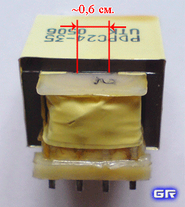
The thickness of the set of plates of the entire magnetic circuit is 2 centimeters. According to the formula, the power of this mini-transformer is equal to about 1 W.

This transformer has two secondary windings, maximum admissible current which is quite small, and amounts to tens of milliamps. Such a transformer can only be used to power circuits with low current consumption.


")


