We take the wall thickness of the nozzle equal to 10 mm (usually it is equal to 8-12 mm).
We take the angle of inclination of the nozzles to the vertical axis equal to 20° when the nozzles are placed on the end part of the head in one row.
According to the obtained data on the dimensions of the nozzles, as well as their angle of inclination to the axis of the lance, by means of graphic constructions, we determine the dimensions and design the design of the collector and the end part of the tuyere head.
In accordance with the obtained dimensions, we select the required diameters of the oxygen supply (Dk), separation (Dr) and outer (Dn) tuyere pipes according to GOST 8732-58 for seamless steel pipes manufactured by our industry. This takes into account the need to ensure sufficient water flow for cooling the tuyere, as well as the ratio of the cross sections of the channels for supplying and discharging water.
In this case, Dk = 325 8 mm, Dp = 377 9 mm, Dn = 426 9 mm.
Based on the data on the distance from the level of the still metal in the converter to the tuyere window in the fireplace, as well as the uppermost position of the carriage for fixing the lance, we determine the length of the latter at 23 m.
Taking into account the distance of the nozzles of the lance from the stationary points of oxygen and water supply to the unit, we choose the length of the flexible metal hose at 23 m.
> Calculation of water consumption for lance cooling
Heat loss (Qf) for cooling the oxygen lance is determined by the formula:
Qph \u003d 3.14 Dn (q1 ln.k. + q2 ln.k.),
Where q1, q2 - respectively, the value of the specific heat flux for the section of the tuyere induced in the cavity of the converter and for the section located above the converter, MJ/m2·h;
ln.k., ln.k. - respectively, the length of the section of the tuyere located in the converter cavity and above it, m;
Dn - outer diameter of the lance, m.
With an outer diameter of the tuyere of 0.426 m and a depth of lowering it into the converter by 6.0 (the depth of lowering is determined by the difference between the distance from the level of a calm bath to the cut of the converter neck and the working height of the tuyere above the bath), heat loss during blowing at q1 = 2500 and q2 = 3750 MJ/m2 h will be:
Qph \u003d 3.14 0.426 (2500 6 + 375 17) \u003d 28592.06 MJ / h or 28599.06 103 kJ / h.
In this case, the weight flow rate of cooling water will be equal to:
where C is the heat capacity of water (4.19 kJ/kg K);
Тout, Тin - water temperature at the outlet and inlet to the tuyere, K.
Typical water consumption for lance cooling
QH2O = GH2O / сH2O = 454925.3 / 1000 = 454.9 m3/h.
> Determination of the operating pressure of oxygen in front of the flexible hose of the lance
First, we determine the pressure of technical oxygen at the inlet to the tuyere according to the formula:
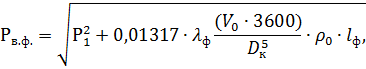
where Rv.f. - pressure of technical oxygen at the entrance to the tuyere, atm;
Dk is the inner diameter of the oxygen supply pipe, cm;
c0 - technical oxygen density under normal conditions kg/m3;
V0 - technical oxygen consumption, m3/s;
P1 - technical oxygen pressure at the nozzle inlet (above taken equal to 14 atm);
lf - coefficient of friction adopted for metal pipe equal to 0.05;
lf is the length of the tuyere, m (23 m was taken above).
After substituting the required values into the equation, we get:
By analogy with the above calculation, we determine the pressure of technical oxygen in front of the flexible hose of the tuyere. The oxygen pressure in front of the flexible hose is determined by a similar expression:
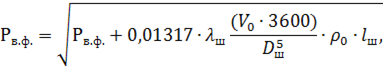
where ls - friction coefficient for metal hoses, taken equal to 0.1;
Dsh - inner diameter of the metal hose, cm.
Table 22 - Main dimensions and operational data of the designed lance
|
Name |
Symbol |
Unit |
Value |
|
1. Oxygen pressure in front of the flexible hose |
|||
|
2. Oxygen pressure in front of the nozzles |
|||
|
3. Oxygen consumption |
|||
|
4. Water consumption for lance cooling |
|||
|
5. Number of nozzles in the tuyere |
|||
|
6. Nozzle diameter in critical section |
|||
|
7. Outlet nozzle diameter |
|||
|
8. Nozzle length including: subcritical length supercritical length |
|||
|
9. Nozzle opening angle |
|||
|
10. Angle of inclination of nozzles to the vertical |
The most promising way to reduce the consumption of fresh water is the creation of circulating and closed water supply systems. With a circulating water supply system, the same water is used many times, with little contamination. Various losses of water in liquid form and in the form of steam are compensated by additional make-up.
Total water loss and water recycling systems per unit of time or per unit of production consists of the following costs:
Irretrievable losses - entrainment with the product or waste……... Q b.p. ;
Costs for watering floors, driveways, plantings ……..…..……Q floor. ;
Evaporation in the circulating water cooler …………….……..…Q app. ;
Entrainment with air from the cooler ……………..…………………..Q un. ;
Natural evaporation from the water surface…………..….... Q isp.est;
Transpiration by the vegetation of the reservoir ……………....…….….Q trans. ;
Filtration from the water supply system into the soil………..……… Q f. ;
Discharge of water into reservoirs for refreshing circulating water (purging)……………………………………………….… Q prod. ;
Reset Wastewater into the reservoir ……………………..…….…....Q sb.st.
Irrevocable consumption and water losses in production in places of its use is equal to
where is the amount of water carried away with the product;
- the amount of water carried away with waste.
Water consumption for irrigation of floors, driveways and plantings determined according to SNiP II-31-74. The volume of watering and washing runoff for the year, m 3, is calculated by the formula
Where A– area of road surfaces, % (usually about 20%);
b- the number of days during which the wash is carried out (for middle lane Russia about 150).
Loss of water to evaporation during cooling Q Spanish , determined by the formula
where ∆ t = t 1 – t 2 – water temperature difference in degrees, defined as the temperature difference between the water entering the cooler (pond, spray pond or cooling tower), t 1 and chilled water t 2 ;
Q cool – recycled water consumption;
TO esp - coefficient taking into account the share of heat transfer by evaporation in the total heat transfer, taken for spray pools and cooling towers, depending on the air temperature (by dry bulb) according to Table. 7, and for reservoirs (ponds)-coolers - depending on the natural temperature in the watercourse according to Table. 8.
Table 7 - Values TO isp depending on the air temperature
Table 8 - TO isp depending on the natural temperature in the watercourse
Loss of water by carryover from the system in the form of droplets Q un. (if water is used as a heat carrier) depend on the type, design and dimensions of the cooler, and for open coolers - on wind speed, etc.
where K un is the coefficient of water loss for carryover:
Table 9- Values of water loss coefficient for carryover (Kun):
Losses of water to evaporation from the water surface of natural reservoirs, as well as the transpiration of water by vegetation should be determined according to the instructions "Instructions for calculating evaporation from the water surface of reservoirs."
Loss of water for filtration determined by a special calculation. These losses insignificant with waterproof bases and weakly filtering fences, with well-filtering bases consisting of pebbles and sand, the size of these losses can reach tens of percent of the water inflow.
Estimated blowdown water flow is
where j add is the allowable coefficient of water evaporation in the circulating cooling system, depending on the composition of the source water and the method of processing additional or circulating water; in cooling towers j add varies from 1 to 6.
The amount of water taken from a natural source
……………………………………………………… m 3 / day
Quantity of output ..……...Q issue =16800 t/day
Humidity of products……………………..…. α=1%
The amount of waste …………….……………..Q waste = 58 m 3 / day
Sediment humidity………………….………..…. β=96%
Recirculation ratio………….………. λ=0.49
Area for irrigation……………... F=0.5 ha
The temperature of the water entering the cooler….…. T 1 \u003d 43.6 ºС
Chilled water temperature………..….…37.3 ºС
Air temperature…………………........... T air =20 ºС
Permissible coefficient of evaporation of water in the system
reverse cooling……………………. φ add = 2
To calculate the cooling system of an automobile or tractor engine, the initial value is the amount of heat removed from it per unit time Q cool . This quantity can be determined from the heat balance equation:
Where q cool- the proportion of the amount of heat removed from the engine. For petrol engines q cool= 800–1300 kJ/kW? s, for diesel engines q cool= 1100–1150 kJ/kW? With.
Having determined the value Q cool , then find the amount of liquid , circulating in the cooling system per unit of time,
![]() ,
,
Where W is the heat capacity of the circulating fluid.
For water C w = 4.22 kJ/kg? K, for ethylene glycol mixtures C w = 2–3.8 kJ/kg? TO;
t out, t in- temperature of the fluid leaving the radiator and entering it, °C.
For radiators of automobile and tractor engines, the value t out – t in= 5–10? WITH.
The engine cooling system is usually calculated for two engine operating modes: at rated power and maximum torque.
The size of the radiator cooling surface (m 2) is determined by the formula:
![]() ,
,
Where k is the total heat transfer coefficient through the radiator walls,
t cool- average temperature of the coolant in the radiator, °С;
![]() ,
,
where t in coolant = 90 ? C is the temperature of the coolant at the inlet to the radiator;
t out cool = 80–85? C is the temperature of the coolant at the outlet of the radiator;
t cool is the average temperature of the air passing through the radiator, °C,
![]() ,
,
where t in cool = 40? C is the air temperature at the radiator inlet;
t out cool = 60–70? C is the air temperature at the outlet of the radiator.
Coefficient k depends on many factors: the material of the cooling grille, the shape and condition of its internal and external surfaces, the nature of the movement of the air flow, etc. The heat transfer of the radiator deteriorates significantly when scale, rust or dirt forms in it.
Value k can be determined by the formula:
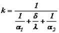 ,
,
Where? 1 \u003d 8500–14500 kJ / m 2? h? K is the heat transfer coefficient from the liquid to the radiator walls;
? is the thermal conductivity coefficient of the metal of the walls (tubes) of the radiator. For brass value? = 300–450 kJ/m? h? K, for aluminum -? = 300–350 kJ/m? h? K, for stainless steel -? = 35–70 kJ/m? h? TO;
? is the tube wall thickness, m;
? 2 - coefficient of heat transfer from the walls of the radiator (tubes) to air, ? 2 \u003d 150–1100 kJ / m 2? h? TO.
Coefficient? 2 mostly depends on air speed ? WHO passing through the radiator, and is expressed by the dependence:
For preliminary calculations of the area of \u200b\u200bthe radiator of the cooling system, you can use the formula:
![]() ,
,
Where f- specific cooling area, m 2 / kW.
For cars f= 0.14–0.3, for trucks f= 0.2–0.4, for tractors f = 0.4–0.55.
Capacity of the liquid cooling system l. (Ne in kW) varies within the following limits: for cars – (0.13–0.35)?Ne, for trucks – (0.27–0.8)?Ne, for tractors – (0.5–1.7)?Ne.
The size of the fan of an automobile or tractor engine must be such as to ensure the supply of air in the amount necessary to cool the liquid in the radiator.
The fan type is determined by the conditional speed coefficient:
![]() ,
,
Where V WHO- fan performance, m 3 / s.
 ,
,
Where? WHO= 1.07 kg/m 3 - air density;
Woz= 1 kJ/kg? K is the heat capacity of air;
H - fan pressure. H = 600–1000 Pa.
With n ref = 15–100, centrifugal fans are used, with n ref = 80–300, axial single-stage fans are used.
2.1.1 Determining the cooling water flow
The consumption of cooling water G in (in kg / s) is determined from the heat balance of the condenser:
where is the enthalpy of steam in the barometric compensator, kJ/kg;
is the heat capacity of water, kJ/(kg K);
C in \u003d 4190 kJ / (kgK);
Initial temperature of cooling water, ºС;
t n \u003d 10 20 ºС
Final temperature of the mixture of water and condensate, ºС.
The temperature difference between vapor and liquid at the outlet of the condenser is 3 ÷ 5 degrees, so the final water temperature is assumed to be 3 ÷ 5 degrees. below the vapor condensation temperature:
![]()
2.1.2 Calculation of the barometric condenser diameter
The barometric condenser diameter ‚ is determined from the flow equation
 , (2.2)
where - vapor density, kg / m 3 selected according to the vapor pressure in the condenser P bq;
– steam velocity, m/s, taken within 15 ÷ 25 m/s.
![]()
According to the NIIKHIMMASH normals, we select a barometric condenser with a diameter of d bc = 600 mm with a pipe diameter of d bt = 150 mm.
2.1.3 Calculating the height of the barometric tube
Water velocity in a barometric tube
Barometric tube height
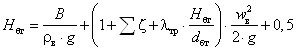 , (2.3)
where V is the vacuum in the barometric condenser, Pa;
is the sum of local resistance coefficients;
is the coefficient of friction in the barometric tube;
are the height and diameter of the barometric tube, m;
0.5 - altitude margin for a possible change in barometric pressure.
where are the local resistance coefficients at the pipe inlet and outlet.
The coefficient of friction depends on the mode of water movement in the barometric tube. Let us determine the mode of water flow in a barometric tube:
where is the viscosity of water, Pa∙s, determined by the nomogram at water temperature t cf.
For smooth pipes with Re = 123250,
2.2 Calculation of the performance of the vacuum pump
The performance of the vacuum pump G air is determined by the amount of air that must be removed from the barometric condenser:
where 2.5∙10 -5 is the amount of gas released from 1 kg of water; 0.01 - the amount of gas sucked into the condenser through the seals per 1 kg of vapor. Then
Volumetric performance of the vacuum pump
![]() , (2.5)
, (2.5)
where R is the universal gas constant, J/(kmol K);
M in is the molecular weight of air, kg/kmol;
t in - air temperature, ºС;
R in - partial pressure dry air in a barometric condenser, Pa.
Air temperature
air pressure
![]() , (2.6)
, (2.6)
where P p is the pressure of dry saturated steam at t v, Pa. At an air temperature of 27.07ºС, Р p = 0.038∙9.8∙10 4 Pa.
Knowing the volumetric air productivity and the residual pressure in the condenser R bk, according to the catalog we select a vacuum pump of the VVN type - 3 shaft power.
Specific energy consumption per ton of evaporated water, ,
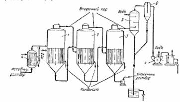
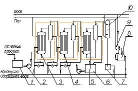
These factors should be taken into account in the technical and economic comparison of devices and the choice of the optimal design. Below are the main areas of use for evaporators various types. For evaporation of solutions of low viscosity ~8 10-3 Pa s, without the formation of crystals, vertical evaporators with multiple natural circulation are most often used. Of them...

It is normalized after thickening with water, skim milk or cream. Water must be boiled and purified. 4. Calculation of a two-case vacuum evaporator Calculation of a two-case vacuum evaporator with a thermocompressor for the production of condensed milk with the development of an evaporator. Initial data: Productivity on the evaporated moisture: W=2000; Working steam pressure: ...
Coolant flow rate, m3/s; G is the mass flow rate of the coolant, kg/h; γ is the vapor density, kg/m3; w is the steam velocity, m/s. Take steam speed 20 m/sec. We summarize the calculations in Table. Table of calculations for fittings of an evaporator installation Name of fitting Steam consumption, kg / h Steam pressure, atm Density, kg / m3 Second flow, m3 / s Steam velocity, m / s Diameter, mm calculated accepted ...


Liquids in the pipes, as well as on the intensity of vaporization. Therefore, in devices with forced circulation, evaporation effectively proceeds at small useful temperature differences. not exceeding 3-5 ° C and with significant viscosities of solutions One of the designs of an evaporator with forced circulation is shown in Fig. 16. The device has a remote vertical heating chamber ...


